Manufacturer's Specifications
Preamplifier:
Frequency Response for Levels to 35 V rms: 0 Hz to 150 kHz, ±0.1 dB; 0 Hz to 500 kHz, ± 1 dB; 0 Hz to 850 kHz, ±3 dB.
Distortion: Less than 0.01% THD (static) or transient intermodulation distortion (dynamic), at all levels from 0 to 25 V.
S/N: Greater than 95 dB (100 dBA), 0.01 Hz to 10 MHz, on line input.
Interchannel Separation: Greater than 80 dB.
Speed: Amplification-stage slew rate, more than 500 V/µS; rise-time, less than 70 nS.
Group Delay: Propagation delay, less than 300 nS, stable from d.c. to 200 kHz.
Input Sensitivity: Nominal level, 100 mV; saturation level, 40 V rms.
Nominal Input Impedance: 100 kilohms.
Output Level: Nominal, 1.55 V rms; maximum, 40 V rms.
Output Impedance: 600 ohms.
Operating Temperature Range: Ambient temperature, -22° to + 104° F (-30° to +40° C); internal temperature, + 113° to + 149° F (+45° to +65° C).
Power Requirements: Nominal line voltage, 115 or 220 V a.c., ± 10%; maximum power consumption, 40 watts.
Dimensions: 19 in. W x 1 3/4 in. H x 12 1/2 in. D (48.3 cm x 4.4 cm x 32 cm); power supply, 3 1/2 in. W x 1 3/4 in. H x 6 1/8 in. D (9 cm x 4.5 cm x 15.5 cm).
Weight: 11 lbs. (5 kg).
Price: With MM or MC phono preamp board, $3,490; without phono board, $2,990.
Amplifier:
Output: Nominal power, 80 watts per channel continuous into 2- to 8-ohm loads and 60 watts per channel continuous into 1to 16-ohm loads; maximum power, 150 watts per channel continuous into 3 ohms; maximum voltage, 35 V peak; maximum current, 25 amperes peak.
Distortion: Less than 0.01% THD (static) or transient intermodulation distortion (dynamic), at all levels from 0 to 25 V into 8 ohms.
Frequency Response for Levels to Nominal Power: 0 Hz to 100 kHz, ±0.1 dB; 0 Hz to 200 kHz, ± 1 dB; 0 Hz to 500 kHz, ±3 dB. S/N: 80 dBA.
Speed: Slew rate, more than 100 V/µS; rise-time, less than 700 nS.
Group Delay: Propagation delay, less than 100 nS, stable from d.c. to 200 kHz.
Input Sensitivity: Nominal level, 1.55 V.
Input Impedance: 50 kilohms.
Operating Temperature Range: Ambient temperature, 22° to + 104° F (30° to + 40° C); internal temperature, + 113° to + 149° F (+ 45° to + 65° C).
Protection Thresholds: High-frequency, 3 V rms at 50 kHz; d.c., 5 V.
Fuses: Short-circuit protection, four 5 ampere fast-blow fuses; power-line input protection, 5-ampere slow blow fuse for 110 V, 3-ampere slow blow fuse for 220 V.
Power Requirements: Nominal line voltages, 110, 117, or 234 V a.c. (selectable), ± 10%; maximum power consumption, 500 watts.
Dimensions: 19 in. W x 2 5/8 in. H x 13 1/8 in. D (48.3 cm x 6.7 cm x 35 cm).
Weight: 27 1/2 lbs. (12.5 kg).
Price: $2,690.
Company Address: c/o International Audio Technologies, 13897 Willard Rd., Suite J, Chantilly, Va. 22021, USA.
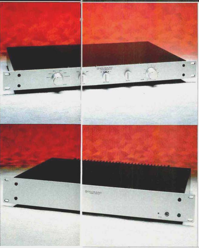
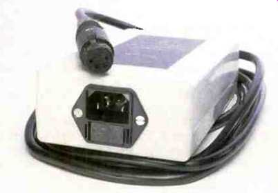
The Goldmund Mimesis 6 and 7 are a solid-state power amplifier and preamplifier imported by International Audio Technologies. These pieces are newer additions to a line consisting of a more expensive preamp and amp, the Mimesis 2 and 3, and several well-respected turntables and straight-line tonearms. If Goldmund's electronics are anything like their tonearms and turntables, they ought to be something else, sonically. (I understand that a CD player and a tuner are in the works and may well be on the market by the time this review is published.) Physically, the Mimesis 6 and 7 are similar in size and appearance, having brushed aluminum, rack-width front panels. The amplifier's panel height is about 2 1/2 inches, and the preamp's is 1 3/4 inches. The preamplifier also has an external power supply.
The preamplifier's phono section is an optional plug-in board and was installed in the unit reviewed here. The jacks and switch position used with this board are labeled "Phono/CD." If the board is not installed, an attenuator is substituted, the "Phono/CD" jacks and selector position can then be used for CD players or other components having extremely high output levels. An identical attenuator is in the AUX 2 input circuit.
Front-panel controls on the preamp, from left to right, are a six-position signal selector, a three-position tape monitor, a three-position "Mute-Phase" switch, and balance and volume controls. All controls are of the rotary type. On the rear panel are nine pairs of WBT gold-plated input/output jacks, a ground post, and a four-pin XLR connector for hookup to the remote power supply.
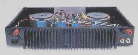
The front panel of the power amp has a small toggle switch for power on/off and an LED for indicating power on. Most of the rear panel is taken up by an extruded heat-sink with vertically oriented! fins. In the approximately 2 1/2-inch square area at the right rear are dual, five-way binding posts for connection to the right speaker and a three-pin a.c. line-cord socket. In the similarly sized area at the left rear are the left speaker connectors and a pair of WBT signal input jacks.
Physical construction of both units is similar, consisting of a bent-up piece forming the rear and sides and, in the case of the amplifier, continuing around to form front subpanels, top and bottom plates and the front panel. The main chassis pieces are bent over in the horizontal plane to form lips or ledges that are about 3/8 inch wide. Around the periphery of these ledges are Pemm nuts for attaching the top and bottom plates. Because of the presence of controls on the preamp's front panel, its sides only extend around in the front about 1 inch to form tabs that have two Pemm nuts each for attaching the front panel. The front panel has two vertical bars of square stock attached to it so that the top and bottom covers can be secured with two screws each along their front surfaces.
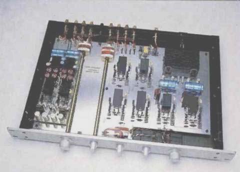
Looking inside the preamp first, we find a large double sided p.c. board that takes up most of the interior area. Mounted above the left side of this board is the optional phono module, oriented lore and aft. It is about 20% as wide as the main board and just about as deep. Just to the right of the phono board is a shaft connecting the front-panel selector knob to the actual selector switch. This switch is located right at the rear of the board, where the inputs are.
The tape monitor switch is similarly located at the rear of the p.c. board. The location of these two switches is really intelligent, minimizing the signal-path length of the high-level circuitry. Continuing on the theme of intelligent layout, the selected source then passes up to the front of the p.c. board, where it encounters the phase/mute switch, balance and volume controls, and part of the output line amplifier.
Passing towards the rear of the board again, the signal goes through the last part of the line amp's circuitry to the output jacks. At the right rear of the p.c. board are the on-board power-supply regulators.
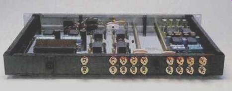
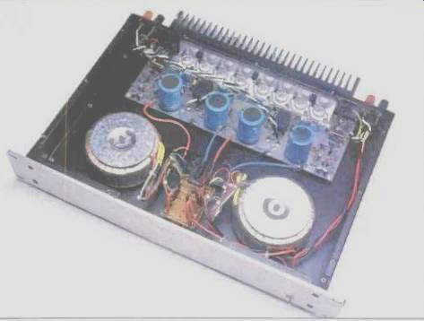
Inside the power amp, it quickly becomes apparent that we have a dual mono design. Two separate toroidal power transformers of approximately 250-VA capacity, along with separate rectifier bridges and a small p.c. board for strapping the transformer primary windings for different voltages, occupy the front half of the interior space. At the rear of the enclosure is the main amplifier p.c. board, which is attached at the rear to the horizontal surface of an L bracket on which the TO-3 output devices are mounted. This bracket, in turn, is mounted to the rear panel of the amp enclosure. Standoffs to the bottom of the enclosure secure the front edge of the amplifier p.c. board. The main electrolytic filter capacitors in the power supplies are mounted right on the p.c. board, where they are very close to their point of use.
Twisted pairs of heavy-gauge MIT wire are used for the input and output connections to the board. Even the a.c. primary wiring appears to be special, heavy wire.
Parts and construction quality in these units is absolutely first-rate, and they are a beauty to behold.
Circuit Descriptions
At my request, Bill Peugh of International Audio Technologies sent schematic information on these units, but he asked that I not reveal the details. To respect his wishes, I will have to be more general than I like in my descriptions.
One thing is apparent by looking at the units themselves: Their circuits are composed of blocks of gain that are, in turn, made up of a combination of potted modules in p.c. board sockets and some discrete parts (resistors, capacitors, and discrete amplifying devices). The modules are potted to maintain thermal stability of their internal components, according to the manufacturer. It appears that these modules are some kind of input circuit that is used in all the blocks, and that the discrete parts which follow are later stage circuitry, ending up in complementary emitter-follower output stages. In the phono preamp board I tested, a pre-preamplifier module precedes one of the gain blocks described above.
The manual does not make clear that this board is for moving-coil cartridges and that a moving-magnet phono stage is also available as an option. It does, however, state that cartridge loading adjustment is no longer necessary due to the proprietary design of the input module. This phono preamp is designed only for moving-coil cartridges or for moving-magnet units that have very low inductance (probably less than several hundred microhenries). The RIAA equalization is partially feedback and partially passive, with the bass boost accomplished in the feedback loop around the gain block following the MC pre-preamp and the high-frequency roll-off occurring in the interstage coupling network at the output of the phono circuit. This last point strikes me as a flaw, in that the RIAA equalization accuracy is dependent on there being a constant load impedance connected across this roll-off network. In normal operation of the Mimesis 7, a load of about 100 kilohms is presented to the selected source. When phono is selected, this 100-kilohm loading of the roll-off network gives some nominal equalization flatness. If a tape recorder or some other signal processing device is connected to tape output, the load on the roll-off network will obviously now be lower, and the equalization will take on various degrees of high-frequency boost. The degree of this effect will be shown in the "Measurements" section of this report.
After signal selection and choice of tape monitor or main selected signal, the signal enters the first gain block in the line section. The output of this first line-amp section feeds another gain block, connected as a unity-gain inverter. The front-panel "Mute/Phase" switch is fed from the gain-block outputs of the first and second line amps. When the switch is in its center (mute) position, its wipers will be grounded; in its other two positions, its wipers will carry signal with 0° (normal) or 180° (inverted) polarity to pass on to the balance and volume controls. The output of the volume control then feeds the input of the last line-section circuit block. From the foregoing, it is apparent that one listens through two circuit blocks in the output amplifier or, if inverted polarity is chosen, three. Note that in this design, the input impedance for the selected inputs is a nice, constant 100 kilohms and that the balance and volume network is between the first and second line-section blocks, where the control values can be low in resistance for extended high-frequency response.
The outputs of the last gain blocks of the line-amp section are coupled to the main signal output jacks through two series resistors whose values add up to 600 ohms. The midpoint of this resistor pair is tied to ground through a pair of normally closed relay contacts. A time-delay circuit controls these relays, providing a turn-on delay of several seconds at power up before the contacts open. Incidentally, the Mimesis 7 has no power switch, the intent being to have the unit continuously powered for best sound.
Power-supply voltage for the circuitry of the Mimesis 7 is higher than usual for solid-state circuitry. Incoming rectified d.c. from the separate power supply is about ±85 V. The on-board regulators in the preamp regulate down to ±60 V. Each circuit block is decoupled, in both the positive and negative supply lines, with series resistors and shunt capacitors. The phono board has an active capacitance multiplier for both positive and negative supply lines. These circuits isolate the supply lines of the phono circuitry from the main regulated supplies by providing the equivalent of some hundreds of thousands of microfarads of shunt capacitance.
Not surprisingly, the circuitry of the Mimesis 6 power amp is like the line-amp blocks in the preamp, with the addition of two pairs of complementary power MOS-FETs connected as source followers for the output stage. A time-delay and protection circuit operates a series relay in the positive output line. Presumably, if excessive d.c. is present at the output, the circuit opens the relay to protect the load. This circuit also functions as a turn-on delay, not connecting the load until a suitable interval has passed. The series feedback resistor for the overall feedback loop is broken into two parallel paths-one from the output stage and the other from the load side of the relay, to help linearize its contacts.
Another function of the relay circuit was discovered when I tested the amp in the lab. The relay opens when frequencies above 2 to 3 kHz are steadily applied at full power. As steady-state power is reduced, the frequency at which the relay opens goes up.
The overall feedback loop is direct-coupled, and since there is no input blocking capacitor, the whole amp is d.c. coupled and should have a d.c. gain the same as its a.c. gain. As always with d.c.-coupled power amps, one must be sure that the preamp used doesn't have any significant d.c. offset--no more than, say, 50 mV. The Mimesis 7 has no problem in this regard, having very low d.c. offset.
Preamplifier Measurements
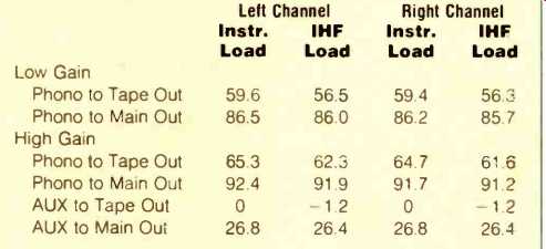
Table IA--Gain (in dB) for Mimesis 7 preamp with IHF and instrument loads,
at low and high gain settings.
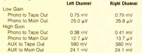
Table IB--IHF sensitivity of Mimesis 7, at low and high gain settings.
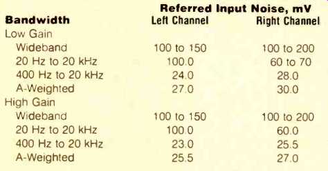
Table II--Phono-section noise referred to input, for zero ohm source impedance.
Some measurements show noise ranges, due to "bouncing" caused by
noise with a frequency-inverse characteristic (¡).
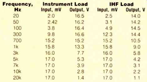
Table
III--Phono overload vs. frequency for right channel of Mimesis 7, with low
gain setting.
Measured gain and IHF sensitivity figures for the Mimesis 7 appear in Table I. The input resistance of the phono board is very low, on the order of 3 or 4 ohms, caused by inverting feedback and/or by common-base-connected input devices. My normal way of measuring gain of high-gain phono stages is to utilize a precision voltage divider consisting of one resistor each of 990 ohms, 9 ohms, and 1 ohm. From this, one gets 40 or 60 dB of attenuation with output impedances of about 10 ohms and 1 ohm, respectively. I usually put something like 1 V into this divider and feed the circuit under test from the 1-ohm output (60 dB), yielding a known 1-mV signal level into the device under test. With devices having normal input impedances (hundreds of ohms or higher), any voltage error caused by the device's input impedance loading down the divider will be negligible.
The phono input impedance of the Mimesis 7, however, would seriously load the 1-ohm source of my divider, so I had to directly measure the input voltage and the stage output voltage to calculate the gain and sensitivity. This low input impedance is apparently what Goldmund is talking about when they refer to special proprietary circuitry that eliminates the need for cartridge loading adjustment. It does tend to equalize the phono stage's output level for MC pickups with different output voltages, to the extent that pickups with higher output voltages tend to have higher output resistances and hence get attenuated more in the input circuit. There is, however, a 6-dB gain switch on the phono board.
Noise as a function of bandwidth and circuit gain is shown in Table II. An interesting property of an input stage like the one used in this preamp is that the apparent noise gels lower as the source resistance goes up. The reason is that the circuit gain is dependent on the input source resistance. Therefore, when a high terminating resistance is used, the gain is lower and so is the apparent referred input noise. For my noise measurements, I put a known voltage of 100 µV at 1 kHz into the phono input by compensating the input to my precision divider just enough to get the desired voltage into the phono input despite the loading effect. The input termination was a short-circuit. Both the A-weighted and band-limited (400 Hz to 20 kHz) noise figures were among the lowest I have measured.
The IHF S/N ratio for components having MC inputs is measured by applying a known 500-0 signal at 1 kHz into the MC input, noting the output level, and calling that 0 dB for reference. The input signal is then removed, and the input jack is terminated with 100 ohms. The residual noise is measured through an A-weighting filter, and the IHF S/N is the difference in dB between the residual noise level and the reference level. When one does this for the phono input of the Mimesis 7, the figure comes out to a fabulous 95 dB. When one applies the 500-0V signal through a 100-ohm resistor, the actual input voltage is a lot lower and the resultant IHF S/N comes out to about 71 dB, more in the neighborhood of what other circuits measure.
Phono equalization error is shown in Fig. 1 for a variety of conditions. As was mentioned earlier, you can see the effects of loading the phono stage at the tape output. The top three curves were measured at the Mimesis 7 preamp's main output, so the phono stage was loaded with the line section's normal 100-kilohm input impedance. My RIAA pre equalizer is terminated in 475 ohms, in series with 10 ohms to ground, so as to provide a normal output at the top of the 475 ohms and a lower impedance, lower voltage output at the top of the 10-ohm resistor. The top curve shows the phono high-gain mode with the circuit fed from the normal output of the pre-equalizer. The second trace is for the low (normal) phono gain. There is some difference in frequency response between the two, in that the relative gain is higher by some 0.15 dB in the high-gain mode below 1 kHz. The third curve down is low-gain mode for a signal from the 10 ohm output of my pre-equalizer. Comparing this curve to the one just above it illustrates how the Mimesis 7's phono circuit equalizes output levels for different input levels with different source impedances: Even though there is a difference of about 34 dB between the unloaded voltages from my pre-equalizer's two output points, the difference between the Mimesis 7's output levels for these two signals was only 1.5 dB! One little subtlety to point out in the third curve is a slight roll-off between 10 and 20 kHz. This suggests that some shunt input capacitance is acting against the 10-ohm source; it does not show when fed from the pre equalizer's normal output, which looks more like a capacitive source.
The shape of these equalization error curves suggests that Goldmund wanted the middle and high frequencies shelved down (or the lower midrange and bass shelved up, depending on your point of view) for sonic reasons. The fourth curve down from the top is for the measurement at the tape out jack, which, for instrument loading, puts another 91 kilohms across the phono preamp output. Now the response between 1 and 2 kHz is starting to tilt up. For IHF loading of 10 kilohms in parallel with 1,000 pF, the effect is more pronounced-and with a load of 3.3 kilohms (an admittedly unrealistic value chosen just to show the point), egad, what a treble boost! Shriek city! My advice is to use a tape recorder with known input impedance of 100 kilohms or higher, if you want reasonable equalization accuracy, and keep any signal processors with input impedances below 100 kilohms out of the tape loop.
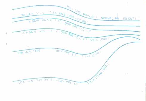
Fig. 1--RIAA equalization error of the Mimesis 7 preamp under a variety of conditions;
notes in parentheses refer to source and output loads. The low, 3.3-kilohm
load which produced the bottom curve would probably not be encountered in normal
use. See text.
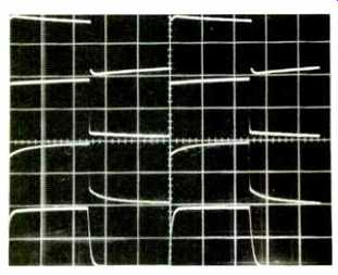
Fig. 2--Response to pre-equalized square waves through the Mimesis 7's phono
input, for (top to bottom) 40 Hz at 0.4 V p-p, 1 kHz at 0.4 V, 1 kHz at
1.0 V p-p., and 10 kHz at 0.4 V p-p. All traces were measured at the tape
output, with instrument loading. (Scales: Vertical, 0.2 V/div. for 0.4-V
curves, 0.5 V/div. for 1.0 V; horizontal, 5 mS/div. for 40-Hz signal, 200
µS/div. for 1 kHz, 20 µS/div. for 10 kHz.) See text.
Figure 2 is a 'scope photo of pre-equalized square waves as they appeared at the preamp's tape output jacks with instrument loading. The top trace is for 40 Hz and shows the general frequency characteristics of Fig. 1. The next trace down is for 1 kHz with an output of about 0.4 V peak to peak.
Response here is linear, and the effect of low-frequency lift is evident. The next trace is again for 1 kHz but at a higher output amplitude. The effects of high-frequency compression are now showing, as the change-of-state amplitude is smaller than the steady-state peak-to-peak amplitude. The bottom trace, for 10 kHz at 0.2 V per division, shows nice high-frequency behavior.
Crosstalk between channels in the normal gain mode was found to be very similar in both directions. It was better than -80 dB up to 400 Hz, rising to about 77 dB at 1 kHz, -69 dB at 10 kHz, and -66 dB at 20 kHz. Crosstalk was in phase.
Phono overload versus frequency and loading is shown in Table Ill for the right channel, which was slightly worse than the left. Input acceptance levels for the high-gain mode are about half of those shown in the Table for the normal gain mode. Another consequence of having the final RIAA high frequency roll-off at the output of the phono circuit is that the ultimate input signal acceptance becomes constant with frequency above about 1 kHz. In full-feedback equalization designs, it would increase with frequency. This is because the output of the gain block preceding the final high-frequency roll-off starts to rise with frequency above 1 kHz and runs into clipping sooner. The input acceptance of this design at 1 kHz is probably okay, as a pickup with an output of, say, 1 mV will produce somewhat less than 1 mV at the Mimesis 7's input. This is due to voltage-divider attenuation of the pickup's output impedance against the input impedance of the phono circuit. The Mimesis 7 nicely meets my criterion of a 20-dB headroom margin over the output at 1 kHz, for a stereo groove modulated at 3.54 cm/S. But at 20 kHz (and this may be excessively stringent), the output theoretically could be 10 mV, and allowing for a 20-dB headroom would require an input acceptance of 100 mV. In view of this, the Mimesis 7's high-frequency acceptance may be marginal for high-output MC pickups that nave low output impedances. With this in mind, I wouldn't consider using the high-gain mode for any pickup with an output level higher than about 100 µV at the standard cutting level (which is 3.54 cm/S). The phono circuit's THD + N was found to be about 0.01% at 10 V rms output from 20 Hz to 1 kHz. For 0.01%, the output attainable decreased to 2.5 Vat 10 kHz and 1.1 V at 20 kHz.
Some aspects of the output section's performance can be seen by comparing the gain and sensitivity figures measured at the main out with those measured at the tape out (Table I). One advantage that comes with high-voltage power supplies is a large output-voltage swing capability. This circuit has it in spades, putting out some 35 V rms at the onset of clipping into my instrument load, decreasing to 32 V with the IHF load, and finally 15 V into 600 ohms. The THD + N into an IHF load was less than or equal to 0.01% from 20 Hz to 20 kHz at 15 V rms output level. Into 600 ohms, the output level for 0.01% or less was 2.5 V. The a.c. line draw of this design is about 0.4 ampere. This is not entirely negligible, being about the power consumption of a 40-watt light bulb. The unit gets very warm in operation. Its top should be left uncovered so as to allow some of this heat to be dissipated.
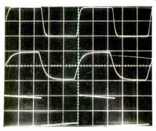
Fig. 3--Response to square waves through the Mimesis 7's line input for (top
to bottom) 100 kHz into instrument load, 100 kHz into IHF load, and 20 Hz into
either load. (Scales: Vertical, 5 V div.; horizontal, 2 µS/div. for 100 kHz,
10 mS/ div. for 20 Hz.)
The referred input noise of the line section is enumerated in Table IV. In the Table, noise is shown for both the normal and inverted polarity positions; the noise is a little higher in the 180° position because of the additional noise from the phase-inverting gain block. As was the case for the phono section, the line section was very quiet. Unlike the majority of other designs, whose balance and volume controls directly feed their line-amp inputs and whose noise gets worse at about the -6 dB point on the volume control, the Mimesis 7's referred input noise stays fairly constant as the volume control is taken down from maximum.
This line-amp section is a fast one. Rise- and fall-times into the instrument load were 0.5 µS. With the volume control down 6 dB, the rise- and fall-times increased to 0.6 µS. They stayed relatively constant and exponential in shape up to output clipping; therefore, this output amp doesn't slew under these conditions. With the IHF load, rise and fall-times were 1.4 µS. Square-wave performance of the output amp is shown in Fig. 3. The top trace is for 100 kHz into the instrument load. The middle trace, also for 100 kHz, is with the IHF load. The bottom trace, for 20 Hz, shows excellent response at very low frequencies.
Output section crosstalk versus frequency was within a few dB of being symmetrical, with the left-to-right direction being the worse. Crosstalk in this direction was better than 80 dB down, from 20 Hz to a few kilohertz, decreasing to 76 dB at 3 kHz. 66 dB at 10 kHz, and 60 dB at 20 kHz. Of note here is that when the volume control was taken down from full clockwise or the balance control was moved from center, the crosstalk at high frequencies did not come up or get worse, as happens in most designs. Crosstalk was, once again, in phase.
The volume control's tracking was found to be within +0.4 to -0.15 dB down to-65 dB of attenuation. Below this point, the channels diverged rapidly, with the right channel dropping out (output going to zero) first. An interesting peculiarity was noticed when I looked at the balance control's operation. When this control was turned to attenuate the measured channel, attenuation was smooth with rotation, as would be expected. However, when turned the other way for the same measured channel, the output level dropped to a maximum of about 2.8 dB at about 30° off center. This means that when the balance control is rotated off center, the overall volume will drop, which might be a bit confusing when trying to alter balance for a particular program source.
Amplifier Measurements
The Mimesis 6 power amp's heat-sinks run pretty hot in normal operation. Thus, when I set up to precondition the amp for the one-hour test at one-third rated power (27 watts per channel), I was wary of how hot the unit might get. Sure enough, about halfway into the hour, the sinks got too hot for me to touch. That's too hot, in my considered opinion, so I aborted the test. Since I didn't see any thermal cutout devices in the amp, I didn't want to take a chance and have it fail. However, I must mention that in normal operation, the sinks don't get much hotter than at idle.
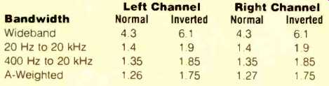
Table IV--Line-amp section noise of Mimesis 7 preamp (in microvolts) referred
to input, with volume control fully clockwise and balance control centered,
for normal and inverted positions of polarity switch. The IHF S/N ratio
was 93.0 dB for both channels and for both polarity positions.
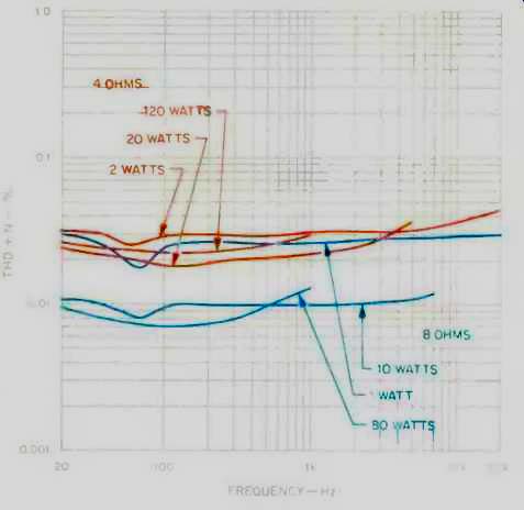
Fig. 4--Mimesis 6 amplifier THD + N vs. frequency for 8and 4-ohm loads, each
at three power levels. The high-frequency cutoffs at higher power levels
are due to the protection circuitry; see text.
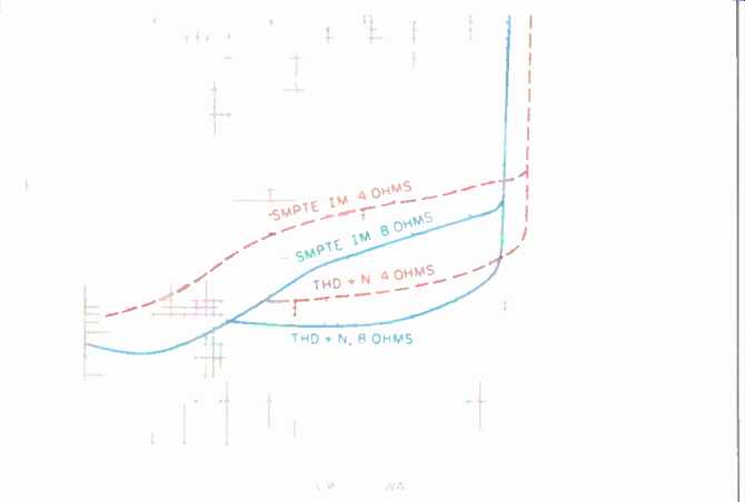
Fig. 5--SMPTE IM and THD + N vs. power for 8and 4-ohm loads. THD + N is for
1-kHz test signal.
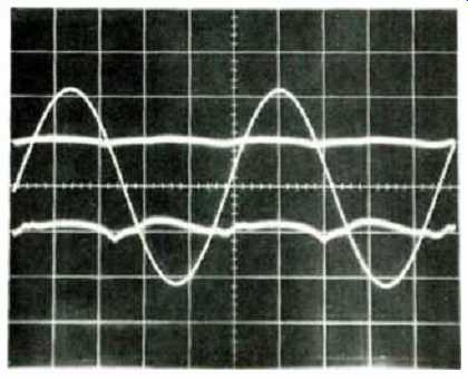
Fig. 6--Typical harmonic distortion residue for 1-kHz test signal. Top residue
curve is for 10 watts into 8 ohms (0.005% THD + N); bottom residue curve
is for 20 watts into 4 ohms (0.009%).
When setting up to measure THD + N, it became apparent that the protection circuitry is very zealous in its task of keeping full-power high-frequency energy out of one's speakers. Attempts at full power above about 1 kHz resulted in the speaker relay's opening. The threshold is obviously level- and frequency-dependent; the threshold is about 3 watts at 20 kHz. Results, such as I could get, are shown in Fig. 4 for 4- and 8-ohm loading. The 1-kHz THD + N and SMPTE-IM distortion for 4and 8-ohm loading are plotted in Fig. 5. Typical harmonic distortion residue for a 1-kHz signal is seen in Fig. 6 for 10 watts output with 8-ohm loading and for 20 watts output with 4-ohm loading. The top residue trace is at 0.005% for 8-ohm loading, and the bottom residue trace is at 0.009% for 4-ohm loading. More high-order nasties are evident in the bottom trace.
Voltage gain of the Mimesis 6 was found to be 30.3 x or 29.6 dB. IHF sensitivity for 1 watt into 8 ohms was 94.5 mV for both channels.
Output noise, in terms of absolute noise level as a function of bandwidth and in terms of S/N relative to 1 watt output, is shown in Table V. The difference between channels tended to disappear when the channels' input grounds were tied together, a condition that would be the case in practical stereo use.
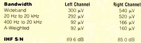
Table V-Mimesis 6 amplifier output noise and IHF S/N.
Channel-to-channel crosstalk as a function of frequency was set up to be measured with the reference driven channel at 10 V rms for good, crosstalk-dominated results. However, the protection circuit prevented data from being collected above about 7 kHz. Results were not symmetrical with direction, with the right-to-left direction being worse. In this direction, crosstalk was better than 80 dB up to a few hundred hertz, rising to 72 dB at 500 Hz, 58 dB at 3 kHz, and -46 dB at 10 kHz before the protection circuit cut in. Crosstalk was in phase.
At the excitation level I generally use (1 ampere rms into the channel under test), the test of damping factor versus frequency ran afoul of the protection circuit at high frequencies. Results are plotted in Fig. 7.
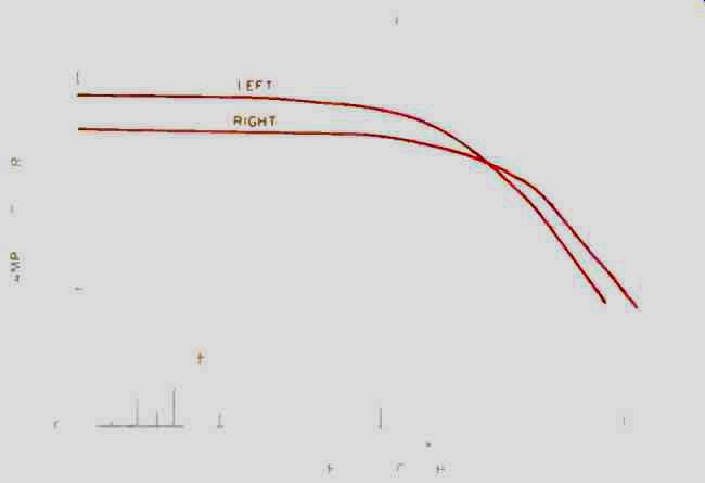
Fig. 7-Damping factor vs. frequency. The high frequency cutoffs are due to
the protection circuitry.
Frequency response at 1 watt output was flat from d.c. to above the audio range, being down about 0.35 dB at 100 kHz into 8 ohms and down about 0.6 dB at this frequency into 4 ohms. Clearly, this is a wide-bandwidth power amp.
Rise- and fall-times at an output of 10 V peak to peak were 0.8 µS into 8 ohms and 1.0 µS into 4 ohms. Again, the protection circuit's vigilance prevented my looking at the edge-transition behavior at a higher level.
Square-wave performance of the Mimesis 6 is shown in Fig. 8. The top trace is for 10 kHz into 8 ohms at an output level of about 10 V peak to peak. In the middle trace, the effect of an additional load of 2 across the 8-ohm load is shown. Lastly, the bottom trace is for a 40-Hz signal; as expected for a d.c.-coupled design, there is no tilt in the exhibited waveform.
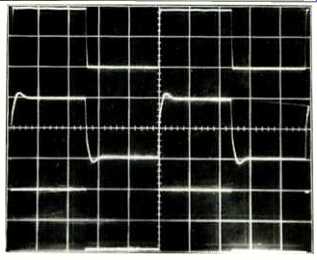
Fig. 8-Square-wave response. Top trace is 10 kHz with 8-ohm load; middle
trace is 10 kHz with 2-uF capacitance across the 8-ohm load; bottom trace
is 40 Hz into 8 ohms. (Scales: Vertical, 5 V/div.; horizontal, 20 µS/div.
for 10 kHz, 5 mS/div. for 40 Hz.)
IHF dynamic headroom came out to 2.6 and 4.8 dB for 8 and 4-ohm loading, respectively, based on the manufacturer's rating of 80 watts nominal power output for 2- to 8-ohm loads. Corresponding power levels in the 20-mS time period of the test-tone burst were 144 and 242 watts. Clipping headroom, again based on 80 watts, came out to 0.61 and 2.1 dB for 8- and 4-ohm loading with power of 92 and 130 watts, respectively, being delivered at the visual onset of clipping.
Use and Listening Tests
The operation of the Goldmund pieces was flawless, with no surprises or glitches. I would recommend leaving the preamp on continuously, as intended, and warming up the amp for at least an hour before critical listening.
Equipment used to evaluate the Goldmund pair included an Oracle turntable fitted with a Well Tempered arm and Koetsu Black Goldline cartridge, a California Audio Labs Tempest CD player, a Nakamichi 250 cassette deck, a Technics reel-to-reel recorder, a Cook-King reference tube phono preamp, and YBA3 and EAR 519 amplifiers. These amps drove Siefert Research Magnum Ill speakers and/or Stax SR-X/Mk3 headphones with the Stax SRD-7 Pro energizer.
First listening impressions of the Mimesis 6 power amp, after it had warmed up for about a day, were that it was a pretty good amplifier. The sound was open and spacious, with good bass and dynamics. Something about it seemed to transmit the emotional quality of music. The amp also sounded very good in a friend's system, with Apogee Duetta loudspeakers.
I have listened extensively to the Goldmund units as a pair, and on the Siefert speakers, the spectral balance is pretty good. Records sounded good but not outstanding.
The sound of CDs through the line section became noticeably more electronic, although the musical quality was generally good. Bass extension and quality were outstanding. I have enjoyed a lot of music while listening to this setup. A brief audition with a pair of Fuselier 3.8D speakers and also with some Jecklin Float electrostatic headphones produced a sound that was too bright and spitty on vocal sibilants when playing CDs. When the same program material was used, but with my EAR 519 tube power amps driving the above-mentioned loads, and using my reference passive switched attenuator volume control instead of the Mimesis 7 preamp line stage, the sound was more balanced spectrally; the spittiness was virtually gone with the Jecklin Float headphones. The sound was still a bit bright on the Fuselier speakers, but that appears to be their characteristic. In a final round of listening, using my Stax electrostatic earphones, I again noticed a spitty quality to female vocals when playing CDs.
I then went through the following changes in the setup: I fed the output of the Mimesis 7 through my stepped attenuator volume control to drive the cable to the power amp location from a different (higher) source impedance, changed to tape out in order to eliminate line-section electronics, bypassed the Mimesis 7 preamp entirely, and finally changed from the Mimesis 6 power amp to my EAR 519 tube amps. There was not much change when going through the stepped attenuator volume control. Eliminating the line amp of the Mimesis 7 by feeding my attenuator from its tape output improved things a bit, and bypassing the Mimesis 7 entirely yielded a small improvement. Changing from the Mimesis 6 power amp to my EAR 519 tube power amps made the biggest difference, with the sound then being free of excessive sibilance and being of quite extraordinary quality.
I realize that all this may be a bit confusing. What I'm trying to say is that the Goldmund pair yielded very listen able reproduction on my Siefert speakers and undoubtedly will with other speakers in other systems. When I put on my pure state-of-the-art hat, started listening through my Stax 'phones, and compared these units to the best I've heard, I found I got better sound using my personal reference setup.
As always, I recommend making one's own listening evaluations of any prospective purchases, and doing so in a variety of circumstances. And I certainly recommend going out to listen to the Goldmund gear.
--Bascom H. King
(Adapted from: Audio magazine, Dec. 1989)
Also see:
Goldmund ST4 Turntable & Gold Cartridge (Aug. 1990)
Linn LK1 Preamp / LK280 Power Amplifier (Apr. 1989)
= = = =