Manufacturer's Specifications:
Power Bandwidth: 2 Hz to 200 kHz.
S/N: Greater than 95 dB.
THD: 0.05% at 2 V rms.
Gain: 14 dB.
Maximum Output: 3 V rms.
Input Impedance: 10 kilohms.
Output Impedance: 600 ohms.
Dimensions: 11 in. W x 3 in. H x 8 1/4 in. D (27.9 cm x 7.6 cm x 21 cm).
Weight: 5 lbs. (2.27 kg).
Price: $399.
Company Address: 1035 Conger, #3, Eugene, Ore. 97402, USA.
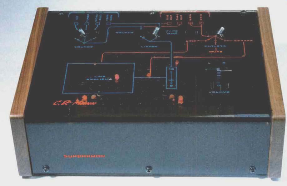
Superphon's C.D. Maxx is an unusual-looking but attractive, not too expensive preamplifier without a phono equalizer. Like a number of similar products, this preamp serves a need for signal selection, volume and balance control, and line-level amplification. Many systems now use CD players as the prime signal source, with no turntable (can anyone who really knows what records sound like imagine that?), which gives line-level preamps like this one a legitimate reason to be.
The C.D. Maxx is cleverly conceived as an overall design. According to the manufacturer, its unique appearance is a matter of form following function. The top cover and front is a piece of smoked Plexiglas that has the signal routing printed on the top surface, with input routing in blue and output routing in red. This handy little feature makes the unit's operation so easy and obvious that reference to the owner's manual for operational help is rather unlikely.
Superphon drew heavily on the technology embodied in their Revelation II preamp; they wanted to leave plenty of clearance around the p.c. board and to use materials with benign dielectric and magnetic properties for the chassis enclosure. Accordingly, a single p.c. board sits about 1 inch down and parallel to the top surface of the unit. Mounted on this board, in addition to the output line-amplifier components, are three 3-position toggle switches for various functions and two linear straight-line volume controls mounted side by side. This construction eliminates long signal path traces and wiring harnesses, thus simplifying the signal path. The handles of the switches and the sliders of the volume controls protrude through slots in the top surface.
Knobs are placed on the volume control sliders. Continuing with the visual aspect, six red LEDs on the p.c. board serve as bias reference elements in the circuitry and look rather neat when the unit is powered up. Finishing up with the physical configuration, a black anodized piece of aluminum is bent in the shape of a U to form the back, bottom, and front subpanel. Half-inch-wide ledges are bent on all sides of the chassis and have Pemm nuts installed. Attractive walnut sides are bolted to the chassis via these Pemm nuts. All in all, this preamp is a rather bold, innovative-looking piece of gear.
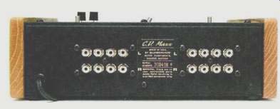
Four signal inputs are provided: "CD," "Tuner," "Video (AUX)," and "Tape Mon." The leftmost toggle switch selects between the first three of these inputs. Whichever signal is selected goes to one input of the tape monitor switch and to one pair of tape output jacks. The tape input feeds directly to the other pair of tape out jacks (labeled "Dub Out") and to the other input of the monitor switch. The output from the tape monitor switch is routed into the two volume control potentiometers.
From the volume controls, the signal goes to the line amplifier and to the "Outlets" selector switch at the right rear of the top panel. This switch, which feeds two pairs of output jacks wired in parallel, can select the signal from the line amp, an unamplified signal direct from the volume control wipers ("Bypass"), or ground ("Mute"). The power transformer is in a small black plastic box that plugs right into an a.c. socket. A two-wire interconnect cord is permanently attached to both the preamp and this transformer box. Components on the p.c. board look to be of reasonable quality and consist of discrete amplifying devices, metal-film resistors, and tantalum bypassing and coupling capacitors. Not a film capacitor is to be found.
Circuit Description
As a schematic was not supplied with the unit, I'll start by quoting a letter from the manufacturer which accompanied the preamp I received for review: The circuit is as novel as the package. Amplification is by single-ended Class-A, differential MOS-FET. This unique wide-band circuit is followed by an FET current-sourced, Class-A MOS-FET buffer. Three shunt-type regulators per channel are woven into the circuitry to place each near the part that it regulates. Each regulator is marked by a light emitting diode (LED) to allow quick visual confirmation of proper circuit operation.
After tracing the circuit, I can attest to the correctness of this description. To flesh it out a bit, the sources of the input differential amplifiers, which are composed of N-channel MOS-FETs, are degenerated by separate source resistors and returned to ground through what appears to be a current-regulating diode. The drains are connected to a PNP bipolar turn-around circuit, with the stage output taken from the junction of the PNP collector and the right-hand (schematically) MOS-FET drain. This point is direct-coupled to the gate of a third N-channel MOS-FET acting as a source follower. The load to ground for this follower is a fourth N channel MOS-FET, interconnected with some other devices as a constant current source. Output of this source-follower stage is coupled to the "Outlets" switch through 20 µF of tantalum capacitors. A direct-coupled feedback divider, from the output source of the follower back to the inverting input of the differential amp, serves to set the a.c. closed loop gain at about 14 dB, and to d.c. divide the desired output operating point down to a level that matches that set into the noninverting input. The shunt arm of this divider is made up of two resistors in series, with the lower one being a.c. bypassed to meet the different a.c. and d.c. gains required. The d.c. level into the noninverting (signal) input is set by an interesting circuit of unusual complexity. According to Superphon, its purpose is "to provide exceptional power-line ripple immunity and to permit shifting the d.c. reference point, which affects sound quality and distortion content." In this circuit, three shunt voltage regulators, made up of zener diodes and LEDs in series, are placed in shunt with the circuit for input-stage d.c. level setting, the input stage itself, and the follower output stage. The incoming a.c. voltage is separately bridge rectified and smoothed with a 330-µF capacitor for each channel. All in all, this is an unusual circuit topology for an audio gain block. I have seen and used it myself for non-audio purposes but haven't seen it employed with MOS-FET devices, as embodied in the C.D. Maxx.
Measurements
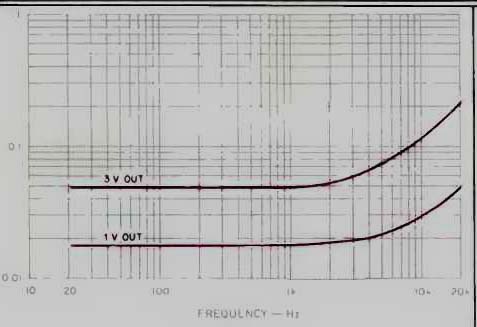
Fig. 1--THD + N vs. frequency, with instrument loading, at two output levels.
With IHF loading, distortion was slightly higher at 3 V out and slightly lower
at 1 V.
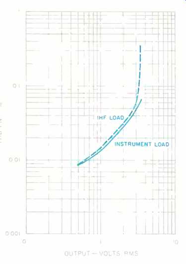
Fig. 2--THD + N as a function of output level, for IHF and instrument loads.
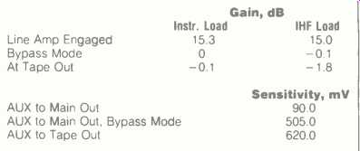
Table I-Gain and IHF sensitivity for both channels.
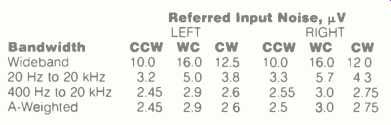
Table II--Line-amp noise, referred to input, for three volume control settings
and different bandwidths; source impedance, 1 kilohm.
---Notes on volume control settings: CCW is counterclockwise or full down, WC is worst-case or near full up, and CW is clockwise or full up.
Line-amplifier gain, with instrument and IHF loading, as well as IHF sensitivity measurements are shown in Table I. Output impedance, with the line amp in, was about 440 ohms; with the "Bypass" mode engaged and the volume control wide open, the output impedance was 100 ohms. As the volume control is turned down to where attenuation is about 6 dB, the output impedance in "Bypass" mode will be a maximum of 10 kilohms (the pot's impedance value) divided by 4, or 2.5 kilohms, plus the 100 ohms of the series output-buffering resistor, for a total of 2.6 kilohms. Output impedance at the tape out jacks was 2.2 kilohms, plus that of the connected source. Input impedance was 10 kilohms, which, in my opinion, disqualifies the C.D. Maxx from use with most tube circuit sources unless those sources are specified as being able to drive 10 kilohms with grace and have output coupling capacitors of at least 10 µF. Since people using tube sources with the C.D. Maxx are probably in a distinct minority, this will not be any real limitation.
Total harmonic distortion plus noise is shown in Fig. 1 for two output voltages with instrument loading. Using IHF loading increased the distortion slightly at 3 V out and decreased it slightly at 1 V out. The dominant distortion product was second-order harmonic. Clipping occurred at about 3.5 V rms output with either instrument or IHF loading. The line amp put out 2 V rms into 600 ohms at the onset of clipping. In all cases when clipping occurred, the positive half cycle squared off first. Figure 2 shows THD + N, at 1 kHz, as a function of output level.
Interchannel crosstalk was down at least 80 dB at frequencies to about 1 kHz but decreased to -66 dB at 5 kHz and to 54 dB at 20 kHz. These results were for the slightly worse (right-to-left) direction, with the volume control at maximum and the line amp engaged. Crosstalk was similar in the "Bypass" mode.
Referred input noise of the line amp is shown in Table II as a function of bandwidth and volume control position.
Rise- and fall-times, with the line amp engaged and at ±2 V output, were 0.7 µS for instrument loading and 1.4 uS for IHF loading. Rise- and fall-times were not noticeably lengthened as the volume was reduced from maximum. Edge shape was exponential, up to the level of clipping, with the instrument load; therefore, no slewing was evidenced. The IHF load did cause slewing of about 5 V/µS on the negative going edge transition at ±5 V output. With this load, slewing stopped when the output level was backed down to about ± 2 V. In "Bypass" mode, at an output level of about ± 0.9 V (which, as an input level to the still-driven line amp, is just pushing it to clipping), rise- and fall-times were on the order of 100 nS with the instrument load, lengthening to about 360 nS with the IHF load. The C.D. Maxx is fast.
Oscilloscope photos of square-wave performance are presented in Fig. 3. The two superimposed traces at the top are for 100 kHz, with instrument and IHF loading, and with the line amp engaged. The middle traces are, for the same 100-kHz frequency but in "Bypass" mode; again, the two superimposed traces are for instrument and IHF loading.
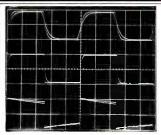
Fig. 3--Square-wave response for 100 kHz with line amp engaged (top) and bypassed
(middle), and for 20 Hz with line amp engaged (bottom). Waveforms for both
IHF and instrument loading are superimposed in each case. (Scales: Vertical,
2 V/div. for top and bottom traces, 1 V/div. for middle trace; horizontal,
2 µS/div. for top and middle traces, 10 mS/div. for bottom trace.)
The bottom traces are for a frequency of 20 Hz, with the line amp engaged and for instrument and IHF loading. With the "Bypass" mode engaged, there was no low-frequency tilt, as the signal passes through no series capacitors and is therefore d.c.-coupled.
Use and Listening Tests
Equipment used to evaluate the C.D. Maxx included an Oracle turntable fitted with a Well Tempered arm and a Koetsu Black Goldline cartridge, a California Audio Labs Tempest CD player, a Nakamichi 250 cassette deck, a Technics 1500 reel-to-reel recorder, and EAR 519 mono tube amps driving Siefert Research Magnum III speakers or Stax SR-X/Mk3 headphones via a Stax SRD-7P energizer.
Records were played through a Vendetta Research SCP-2A phono preamp and the Cook-King reference tube phono preamp.
First listening with the C.D. Maxx was with the Vendetta Research phono preamp as a signal source. I compared the sound of this phono preamp, going through my reference passive switched attenuator (very good sound, by the way), to the sound going through the C.D. Maxx in both its "Bypass" and normal modes. Much to my surprise, the sound through the C.D. Maxx was just about as good. Detail and space weren't quite as good, but otherwise the reproduction was most acceptable. The sound in the "Bypass" mode was closer to the reference but maybe a bit harder. Using the line amp softened the sound slightly, and I preferred the sound with the line amp engaged.
I quickly overcame my reluctance to use the tube CD player, as I wanted to hear some of my music on CDs. The California Audio Labs Tempest player has a 1-uF output coupling capacitor, and when combined with the Tempest's output resistance of about 5 kilohms and the C.D. Maxx's input impedance of 10 kilohms, the low-end cutoff frequency is about 10 Hz. The low end did not sound as good as it did through my reference setup, which loads the source with about 50 kilohms; the deep bass wasn't as strong, and the damping sounded looser in the range from 50 to 100 Hz.
This is not a fault of the C.D. Maxx but a fault in the source's reaction to being loaded with 10 kilohms. Aside from the bass, the rest of the range sounded very good with CDs, and I found myself listening happily, with no feeling that I needed to take the C.D. Maxx out of the setup and go to my reference volume control.
Finally, I used the Cook-King reference tube preamp to play records. This circuit can drive 10 kilohms with grace, and its output coupling capacitor value is 20 µF, so there is no problem using it with the C.D. Maxx. Using this preamp as a signal source, the sound was noticeably less open and detailed when going through the C.D. Maxx, though in this case, I preferred the sound not going through the C.D. Maxx line amplifier.
Operationally, I got used to the side-by-side volume control sliders and found them easy to set for level and balance, adjusting them with the thumb and index finger of one hand or with the thumb only. The selector switches felt a little clunky and coarse but functioned okay.
In conclusion, for the price (which is cheap, for this sound quality), and even without considering the money involved, the Superphon C.D. Maxx preamplifier is one terrific-sounding little device.
-Bascom H. King
(Source: Audio magazine, Dec. 1989)
Also see: Sumo Athena Preamp (Aug. 1989)
= = = =