Manufacturer's Specifications:
Power Output: 35 watts per channel into 8 or 4 ohms.
THD: 0.3%.
Dynamic Headroom: 1.2 dB.
Full-Power Bandwidth: 30 Hz to 21 kHz.
S/N: Greater than 100 dB.
Input Impedance: 100 kilohms.
Dimensions: 16 in. W x 63/8 in. H x 12 in. D (40.6 cm x 16.2 cm x 30.5 cm).
Weight: 35 lbs. (15.9 kg).
Price: $1.695.
Company Address: W141 N9316 Fountain Blvd., Menomonee Falls, Wisc. 53051.
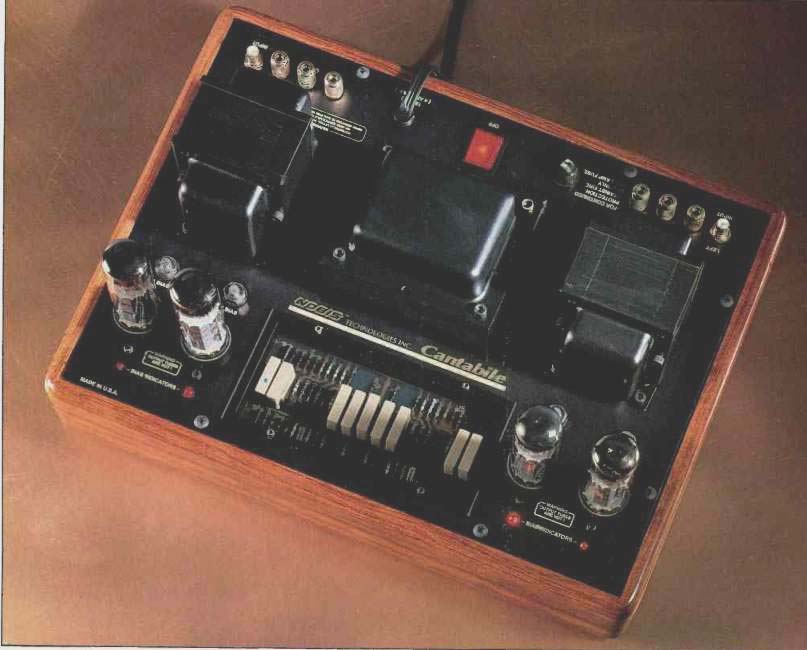
The Cantabile is yet another in the growing list of new amplifiers using tubes. Nobis is known more for their speakers than their electronics, though they also make the EC-1 electronic crossover used with their DMS-1a subwoofer and recently introduced an all-tube preamp, the Proteus. The Cantabile is a hybrid design, with a solid-state front-end and a transformer-coupled tube output stage, and is rated at 35 watts per channel. Though the owner's manual does not discuss it, the amplifier's nameplate says "Class A," and a brochure that came with the unit refers to Class-A operation of the output stage. I checked on the extent to which the amp does operate in Class A and will talk about this in the "Measurements" section.
Construction of the Cantabile is simplicity itself. Everything is mounted to one flat metal plate, the chassis of the amplifier. This plate sits in a box with nice-looking wood sides and a fiberboard bottom. That's it! As can be seen from the photograph, the output tubes are lined up along the front of the unit. Between the sets of output tubes is a plastic window covering the front-end circuit board. Behind each output tube is a screwdriver-adjust potentiometer for setting that tube's idling current. In front of each tube is an LED indicator used when adjusting tube bias. During bias adjustment, the LED indicators extinguish when the proper bias point is reached, as they do on many other amps with LED bias indicators. What sets the Cantabile's arrangement apart is that each LED comes back on again if the associated pot is turned past the narrow zone where optimum bias is achieved.
The output and power transformers are lined up behind the bias pots, with the power transformer in the middle.
Along the rear edge of the chassis are the input and output connections, the line cord and fuse, and a rocker-type power switch. The output binding posts accept either dual-banana plugs or bare wire up to at least 10-gauge. Both output and input signal connectors are high quality. All in all, I found the Nobis Cantabile amplifier an elegant and attractive package.
The signal circuitry of the Cantabile amp is an interesting modern adaptation of several older ideas. The first of these is a solid-state version of the old common-cathode first-stage amplifier. This stage is direct-coupled to the second stage, a split-load phase inverter. Each "equivalent tube" is a cascoded combination of a junction FET driving a MOS-FET.
The second good old idea is taking a portion of the second stage "cathode voltage," low-pass filtering it, and using it to bias the input device. In effect, this forms a sort of d.c. bias servo that compensates for variations in power-supply voltage and temperature by linking the second stage's operating point to them. This scheme was used a lot in early transistorized direct-coupled designs.
The output stage of the circuit is quite conventional and consists of an ultralinear-connected set of EL34 output tubes with fixed bias. Each output tube has its own bias control and LED bias indicator. An IC window-comparator circuit compares the voltage drop across a 10-ohm cathode resistor (representative of total tube current) to a fixed reference and is so arranged that the LED is extinguished when these potentials are equal.
The high-voltage power supply is conventional, consisting of a capacitor input filter fed by solid-state rectifier diodes in a full-wave circuit. The filter capacitor is 800 uF at 450 V d.c., providing a healthy amount of energy storage. This main high-voltage point directly feeds the output transformers' center taps. Another RC filter section feeds a reduced voltage to the solid-state front-end. The tube heaters are a.c. powered. A half-wave rectifier off a tap in the power transformer's high-voltage secondary is fed through a capacitor input filter to the bias-adjustment circuits.
Measurements
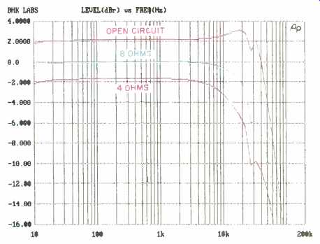
Fig. 1-Frequency response vs. load on 8-ohm tap.
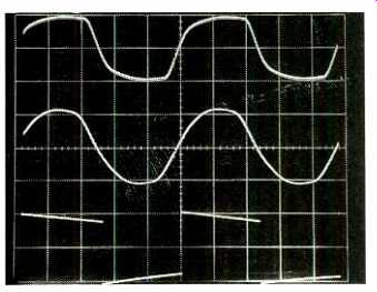
Fig. 2-Square-wave response for 10 kHz into 8-ohm load on 8-ohm tap (top),
10 kHz into 8 ohms paralleled by 2 µF (middle), and 40 Hz into 8 ohms (bottom).
Scales: Vertical, 5 V/div.; horizontal, 20 µS/div. for 10 kHz, 5 mS/div.
for 40 Hz.
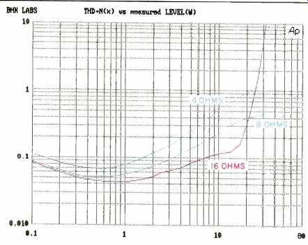
Fig. 3-THD + N vs. power at 8-ohm tap.
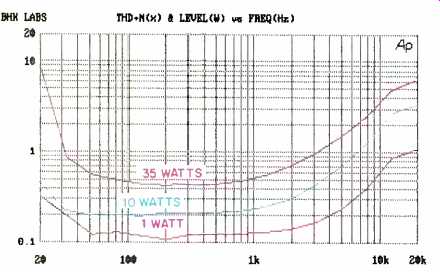
Fig. 4--THD + N vs. frequency as a function of power into 8-ohm load on
8-ohm tap.
Sensitivity and gain were first measured on the 8-ohm taps with 8-ohm loads. The IHF sensitivity for a 1-watt output was 205.5 and 204.5 mV for the left and right channels, respectively. Gain was 22.77 and 22.82 dB, which is lower than the usual power amp gain of 26 dB or more. With about 3-dB less gain at the 4-ohm taps, it may be difficult to get enough playing volume when using passive line preamps with low-output sources. With ordinary active preamps, however, there should be enough overall gain.
Frequency response of the right channel is shown in Fig. 1 for open-circuit, 8-ohm, and 4-ohm loading on the 8-ohm tap. As can be seen, high-frequency bandwidth is not particularly extended and is 3 dB down at about 23 kHz with 8-ohm loading. Some evidence of output transformer resonance can be seen in the region around 30 kHz. Further, judging by the way the output varies with the load, the output impedance is fairly high.
Square-wave response is shown in Fig. 2. The top trace is a 10-kHz signal into an 8-ohm load on the 8-ohm tap. The middle trace shows the effect of adding a 2-uF capacitor in parallel with the 8-ohm load. While rise- and fall-times in the top trace are commensurate with the frequency response shown in Fig. 1, the 2-tLF capacitor slows the response and makes the square wave peak at the edge of the audio band. The bottom trace, for a 40-Hz signal into 8 ohms, exhibits satisfactorily little tilt.
Total harmonic distortion plus noise at 1 kHz, as a function of power output and loading on the 8-ohm tap, is shown in Fig. 3. Load tolerance in this design is typical for an ultralinear output stage: Maximum power is obtained when the load matches the tap, and most of that power is still available with half the nominal load; however, power drops off noticeably when the tap sees twice its nominal load. I generated a curve of 5-kHz distortion versus power output for 4-ohm loading on the 4-ohm tap and compared it to a similar curve for 8-ohm loading on the 8-ohm tap (neither curve shown) and found them to be essentially identical.
This is not true of some other tube amplifiers, whose performance changes from tap to tap because of poor coupling between the output transformer's secondary winding. The Nobis Cantabile does quite well in this test.
Total harmonic distortion as a function of frequency and power is plotted in Fig. 4. Performance of this hybrid amp is similar to that of amplifiers that use all-tube circuits. A spectrum of the harmonic-distortion residue at 10 watts output (Fig. 5) mainly shows low-order second and third harmonics, although the eagle eye of the Audio Precision test computer reveals the existence of a healthy series of higher order (but low-magnitude) components.
Damping factor for the left channel is shown in Fig. 6. (The right channel's damping factor was slightly lower.) The relatively low damping factor is a sign of the high impedance typical of most tube amplifier circuits. Its effect will be to make the output frequency response to the speakers a strong function of the speaker loads' impedance variations.
Output noise levels and IHF signal-to-noise ratios are presented in Table I. Results are quite good here. Interchannel crosstalk was down about 70 dB throughout most of the audio band.
My measurement of dynamic headroom, using the IHF tone-burst signal, yielded an output power of about 40 watts at the visual onset of clipping. This corresponds to a dynamic headroom of 0.6 dB. Steady-state power output at the onset of clipping was about 37 watts for a clipping head room figure of 0.24 dB. These measurements were done with 8-ohm loading on the 8-ohm tap.
How Class A is the Cantabile? The theoretical idling power for a push-pull Class-A output stage, assuming no losses, is twice the output power at the onset of clipping into the designed load. In the Cantabile, the plate power at idle is about 27 watts per tube, a total of 54 watts per channel, rather than the 70 watts you'd expect from the amplifier's power rating. One of the requirements for Class-A operation is continuous current to the individual output devices, with no cutoffs during the signal cycle. When I used a 'scope to monitor the voltage drop across the cathode resistors, I found the current was cutting off for part of the signal cycle when I increased the output power to some 15 or 20 watts.
Another Class-A requirement is that the power to the output stage stay constant from zero to full output. In this amp, the input a.c. line current varied from an idle value of 1.6 to about 2.0 amperes at an output of 35 watts per channel.
Conclusion: Not strictly Class A, but certainly a very rich (high idling power) Class AB!
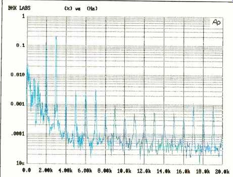
Fig. 5--Spectrum of harmonic-distortion residue at 10 watts out.
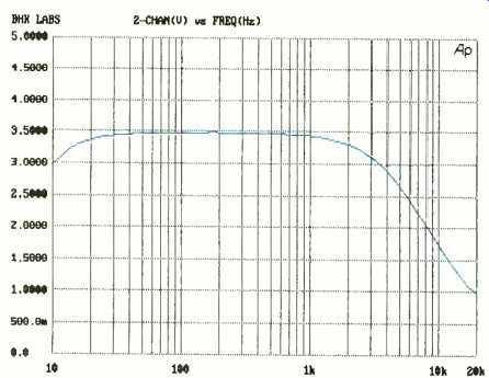
Fig. 6-Damping factor vs. frequency.
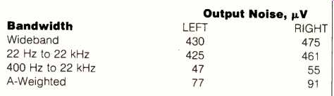
Table I--Output noise. The A-weighted IHF S/N ratio was 89.9 dB for the
left channel and 91.3 dB for the right.
Use and Listening Tests
Front-end equipment used to audition the Cantabile amplifier included an Oracle turntable fitted with a Well Tempered arm and Spectral Audio MCR-1 Select cartridge, a Krell Digital MD-1 CD transport feeding a PS Audio UltraLink D/A converter, a Nakamichi 250 cassette recorder and ST-7 tuner, and a Technics 1500 open-reel recorder. Phono preamplification was competently handled by a Vendetta Research SCP-2B. Preamplifiers used were a Quicksilver Audio and a passive First Sound Reference II. Other power amplifiers on hand during the review period were a prototype pair of Quicksilver M-135s, a pair of custom triode tube amps, and an Arnoux Seven B digital switching amplifier. Loudspeakers used were Win Research SM-10s and Scientific Fidelity Teslas.
My first impressions of this little amp were that it had considerable resolution and detail, with a touch of upper midrange brightness. After using it awhile and, I guess, breaking it in a bit, I generally found its sound musically satisfying. Compared to the Quicksilver prototypes (which are separate mono units of higher power) the Cantabile sounded more forward and less spacious, with a smaller apparent soundstage. At times, depending on the particular software, the sound could be a bit harsh and bright, even at power levels that were not anywhere near clipping. The speakers didn't "disappear" quite as successfully as with other amplifiers I used; frequently, some sounds would seem to be coming more from the speakers than from points in the space around them. Bass response, though not as prominent as with other amplifiers I used, did have a tight character, without flabbiness. Overall, however, performance was pretty good.
One nit that I must pick is that the locking nuts on the bias pots were set too tight for easy adjustment on my review sample. Normally, fixing this would simply be a matter of loosening a lock nut, making the adjustment, and then retightening the nut to prevent accidental readjustment. In the Cantabile I tested, however, loosening this nut also loosened the pots. This allowed some of the pots to turn during adjustment, which could have caused wires beneath the chassis to short or break.
In conclusion, the Cantabile is an interesting design that works pretty well and sounds pretty musical in the process.
-Bascom H. King
(adapted from Audio magazine, Dec. 1992)
Also see:
Dynaco Stereo 70 Series II Tube Amp (Nov. 1992)
Mobile Fidelity Sound Lab UltrAmp Preamp and Amp (Dec. 1992)
= = = =