By BASCOM H. KING
Like the two other Sonic Frontiers D/A converters I've had the pleasure of using, the Processor 3 is a hybrid design, with tubes in its analog output stage and solid-state components every where else. But unlike its predecessors, the Processor 3 has an external power supply and was designed with upgrading in mind; its modules can be quickly unplugged and replaced as new developments in digital audio occur.
The Processor 3 is also the first home audio component to have an input for the new I2S-enhanced (I2S-e) digital bus. Instead of a current-to-voltage (I-V) converter on the DAC chip, the Processor 3 has a discrete I-V module in order to re-create the analog signal more faithfully. As in previous Sonic Frontiers models, a proprietary inductor-capacitor low-pass filter is inserted after the I-V converter to help keep oversampling-frequency components out of the audio signal. The output buffer uses two tubes per channel.
Its outputs are directly coupled and have servo circuitry to minimize DC offset.
Sanyo Oscon electrolytic capacitors are used in the DAC power-supply regulators for their extremely low equivalent series inductance and resistance. Arlon, a hybrid Teflon material, is used for the DAC section's circuit board.
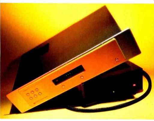
The front panel is simple. There is a pushbutton for each of the six inputs: two coaxial (one with an RCA jack and the other with a BNC connector), one AES/EBU (an XLR jack), two optical (Toslink and ST glass-fiber), and one I2S-e. The selected in put is indicated in the display, as is the sampling frequency of the incoming signal (even 88.2 and 96 kHz, which future standards may require). The display also has indicators for signal lock, muting, HDCD, and polarity reversal. Two pushbuttons beneath it select output polarity ("Phase") and the brightness of the display itself. The only other button switches power between standby and operating modes. The rear panel carries the six digital input connectors, RCA jacks for coaxial digital and un balanced analog output, a pair of XLR balanced analog output jacks, and a multipin connector for the power-supply cable.
Removing the top cover (which is very heavy and dead-sounding, thanks to a lining of vibration-damping material) reveals four circuit boards that occupy virtually all of the Processor 3's interior. One, behind the front panel, holds the panel controls and display. Two boards are at the rear of the chassis, one for the digital inputs and input receiver and the other for the tube output stage. The fourth and largest board holds the DAC modules and their power-supply regulators, the new I-V converter modules, and the passive LC low-pass output filters. The power supply's interior is occupied by one circuit board that carries all of the rectifiers, filter capacitors primary voltage regulators, and ancillary parts. Parts and build quality are of a high order in both chassis.
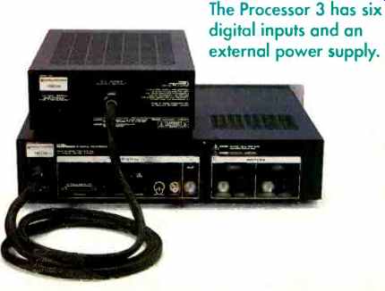
The Processor 3 has six digital inputs and an external power supply.
---------
Dimensions:
Main chassis, 19 in. W x 141/4 in. Dx41 in. H (48cm x 36cm x 11.5 cm); power supply, 9 in. W x 13 in. Dx4 in. H (23 cm x 33 cm x 10 cm).
Weight: 30 lbs. (14 kg).
Price: $6,995.
Company Address: 2790 Brighton Rd., Oakville, Ont. L6H 5T4, Canada; 905/ 829-3838; sonicfrontiers.com.
----------
Measurements
The frequency response curves in Fig. 1 were taken at the Processor 3's balanced outputs. Switching from instrument to IHF loading with unbalanced output dropped the level only about half as much, because the unbalanced outputs' impedance is half that of the balanced outputs.
De-emphasis error was essentially zero. On 1-kHz square waves, ringing was sym metrical and the peaks were unclipped. The symmetry is characteristic of finite-impulse-response (FIR) digital filters; the absence of peak clipping is characteristic of the Pacific Microsonics PMD-100 digital filter/HDCD decoding chip used in the Processor 3.
As can be seen in Fig. 2, total harmonic distortion plus noise (THD + N) at 1 kHz, distortion is higher for unbalanced output than it is for balanced output and with IHF rather than instrument loading. Even at its worst, however, THD + N won't be very noticeable: Its maximum level,-70 dBFS, amounts to a mere 0.03%. And that maximum is attained only near digital full scale (0 dBFS), well above typical music levels.
(The distortion rise occurred in the tube output stage, as I determined by tracing it back through the circuit.) Furthermore, as Fig. 3 reveals, distortion does not rise much with frequency and doesn't even begin to climb until about 2 kHz.
Deviation from linearity for a 500-Hz in put signal (Fig. 4) is very good; linearity is nearly perfect down to-105 dBFS. This was borne out by a noise-modulation test, devised by Richard Cabot of Audio Precision, in which noise spectra are analyzed for a 41-Hz signal at five levels from -60 to -100 dBFS. The Processor 3's noise spectra (not shown) were almost identical at every level.
Interchannel crosstalk was outstandingly low: -120 dB or better from 20 Hz to 15 kHz, increasing to about -105 dB at 20 kHz.
S/N ratios are listed in Table I. The excellent wideband results testify to the effectiveness of the LC filters that follow the Processor 3's DACs. Because noise common to both phases of the balanced outputs cancels out, the noise at those outputs is noticeably lower. This can be seen in Fig. 5, an analysis of the noise for a 1-kHz signal at -80 dBFS. Whether I used balanced or unbalanced output, quantization noise was no more than -93.4 dBFS, and dynamic range was 96 dB or better.
For all the tests that I've described so far, I fed signals to the Sonic Frontiers Processor 3 via an AES/EBU balanced interconnect. I found that there were no significant differences when I repeated several tests via the I2S-e bus connection, although some noteworthy differences emerged when I compared jitter performance.
To determine the I2S-e link's effect on jitter, I first obtained a Sonic Frontiers SFT-1 CD transport that had been modified to include an 12S-e output. I put the SFT-1 in pause mode and connected it to the Processor 3's AES/EBU and I2S-e inputs. Next, I measured jitter at each DAC module for each type of connection. My test points were the modules' deglitch inputs, which work with the digital filters' deglitch outputs to prevent switching noise during transitions from one bit to the next.
As Fig. 6 reveals, switching from the Processor 3's AES/EBU to its I2S-e connection considerably reduces random jitter over most of the audio range, even though the I2S-e curve has slightly more prominent peaks at 120 and 240 Hz (related to the AC line frequency) and slightly higher jitter above 10 kHz. (With AES/EBU connections, the digital input receiver's phase-locked loop, whose cutoff frequency occurs at about 1 kHz, causes a high-frequency rolloff in the jitter spectrum.) Note that the jitter levels in Fig. 6 are peak to peak; the equivalent sine-wave jitter would be 3.54 nanoseconds rms for 10 nanoseconds peak to peak, 1.12 nanoseconds rms for 3 (actually, 3.16) nanoseconds peak to peak, and so on. When I played a jitter-prone -90 dBFS signal on the CBS CD-1 test disc, the Sonic Frontiers' jitter was again lower in I2S-e mode. The reduction I recorded was about 26 dB for the 1-kHz test signal and 14 dB for its second harmonic; that's impressive.
-------------------
Technical Highlights
The Sonic Frontiers Processor 3 D/A converter has six digital inputs. Five of them are common types (two coaxial, two optical, and one AES/EBU) and are selected via four double-pole, double-throw relays.
Each of the coaxial inputs passes through a two-pole LC low-pass filter whose cutoff frequency is about 30 MHz. Signals from either coaxial jack or the AES/EBU input pass through a 1:2 step-up isolation trans former, whose output is passed on as a balanced signal. Toslink and ST input signals are sent through optical receivers, which are referenced to the digital section's power-supply ground; output of the ST input's digital receiver also passes through a differential comparator. Because the selector section has a two-phase output, each optical input's physical ground point is used as the source for the negative signal phase. This helps reduce the effect of any induced noise and jitter in the circuit board traces leading up to the digital input receiver, an Ultra-Analog AES21.
The sixth of the Processor 3's digital in puts is a new type, an I2S-e connection. Its clock and data signals are all isolated via 1:1 transformers. Each transformer is resistively terminated and coupled to high-speed Motorola PECL (positive emitter-coupled logic) chips, which square up the signals to 1-nanosecond switching speeds. Fast multiplexer chips at the input to the Processor 3's digital filter and HDCD decoding chip, a Pacific Microsonics PMD-100, select data and clock signals from the squared-up I2S-e signals or from the digital receiver for the other inputs.
The Processor 3 has two UltraAnalog DAC modules, one per channel. The PMD 100's left and right data outputs reach them via four XOR (exclusive-or) gates, which drive each DAC module's two channels in push-pull and reverse the output signal's absolute polarity when commanded by the front-panel "Phase" switch. The serial bit-clock and word-clock signals from the PMD-100 pass directly from the digital filter and HDCD decoder to the DACs. And the PMD-100's deglitch output, the critical timing signal for the DAC modules, is re-clocked by the master clock en route to the DAC section.
Push-pull, or differential, output from each DAC module is fed into two custom current-to-voltage (I-V) converter modules, one for each signal phase. A two-position, relay-controlled balanced attenuator can be activated to compensate for the 6-dB level difference between normal and HDCD-encoded discs. However, the Processor 3 leaves Sonic Frontiers' factory with this attenuator bypassed by an internal jumper, to provide maximum S/N for non-HDCD discs. Attenuated or not, the audio signals then go to a proprietary balanced LC low-pass filter that rolls off the signal below 176.4 kHz to just about eliminate out-of-band ultrasonic oversampling components in the output.
From the LC low-pass filter, the signal is capacitively coupled to the control grids of the output buffer stage's tubes. Two 6922 dual triodes are used for each channel, one per signal phase. To minimize output impedance, both halves of each tube are paralleled, and the tubes are connected as cathode followers. Each signal phase's cathode follower is loaded with a one-transistor, constant-current source and is DC-coupled (via a series muting relay and another LC output-RF filter) to the analog output jacks.
An op-amp servo compares DC at the tubes' cathode outputs to 0 volts and changes the grid-leak resistance to eliminate any output DC offset it detects.
The power transformer in the supply chassis feeds seven full-wave rectifier bridges and capacitor-input filters, each from a separate secondary winding. The high-voltage bridge uses discrete, fast-recovery rectifiers instead of the common four-diode packages used for the other rectifiers. The high-voltage supply is RC-filtered to develop about +165 volts and then passed through the interconnect cable to the main chassis, where it powers +110-volt Zener-follower discrete voltage regulators for the tube stage. The low-voltage supplies (including a-9-volt supply, which also feeds the tube stage) contain three-terminal IC regulators, some in the power supply and others in the main chassis.
All in all, the design of the Sonic Frontiers Processor 3 is quite complicated yet elegant and sophisticated. B.H.K.
-----------------------
-----------------------
The I2S BUS
Prized as they are by audiophiles, separate CD transports and D/A converters have an Achilles heel: jitter, or variations in clock-signal timing. Its three main causes are standing waves in the cables and connectors linking the transport and the converter, contamination of the clock signal by cross talk from the signal data, and timing errors that arise in the converter's input section.
In one-piece CD players, connections between the transport mechanism and the DAC are short and direct, and the clock and data signals are kept separate. Many of these players have an internal Inter-IC Sound (I2S) digital audio data bus (defined by Philips when the Compact Disc was first developed). This bus uses four separate signal lines--one each for the master clock, serial bit clock, word clock, and serial data.
Connections between separate CD transports and D/A converters, however, are usually in the form of S/P DIF or AES/EBU digital audio interfaces, both of which use digital transmitter chips to combine the four clock and data signals into one composite signal hat can be sent through simple cables.
In a conventional stand-alone D/A converter, where a digital input receiver separates the four original components from the composite signal, the input receiver's imperfections can be yet another source of jitter.
At one time, Audio Alchemy at tempted to circumvent this process by using the original I2S bus to transmit clock and data separately between transports and D/A converters. (A few other companies introduced products using the I2S interface.) This bus was the basis of the I2S-enhanced (I2S-e) interface developed by UltraAnalog, which will license it to other makers.
Its enhancements include extra timing-signal lines and the addition of flags for sampling-clock frequency, clock status (master or slave), and pre-emphasis. For now, only the Sonic Frontiers Processor 3 has this inter face, although the company also has a transport with I2S-e output in the works.
Proprietary cabling is not required for I2S-e connections; the interface was designed for use with a standard professional video cable, the 13W3, which comprises three 75-ohm coaxial cables and five twisted pairs in an overall shield, with 10-pin D-Sub miniature hybrid cable connectors on each end. The I2S clock and data signals are all transmitted differentially, with the master clock using two of the coaxial cables and the remaining clock and data signals using three of the twisted pairs. (The clock and pre-emphasis flags and two transport digital grounds use the remaining twisted pairs.) In a D/A converter, these received signals can be used directly to operate the DAC chips but are usually isolated and reclocked at the DACs by the received master clock for lowest overall jitter.
As a Level 2 I2S-e device, tie Sonic Frontiers Processor 3 uses a master clock signal that is generated in the transport to control its DAC chips. In Level 1 products, master clock signals generated in the D/A converter will control the CD transport, which UltraAnalog says will result in the lowest jitter if the transport's clock is at least as good as the D/A converter's.
(Incidentally, the third coaxial cable in the 13W3, currently unused, is reserved for the Level 1 clock-signal connection.) Level 1 and Level 2 devices can be used together but will operate in Level 2.
-------------------
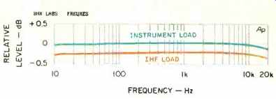
Fig. 1--Frequency response at balanced outputs.
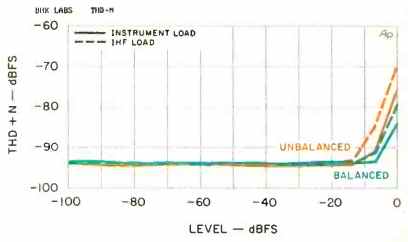
Fig. 2--THD + N vs. level.
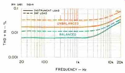
Fig. 3--THD + N vs. frequency.
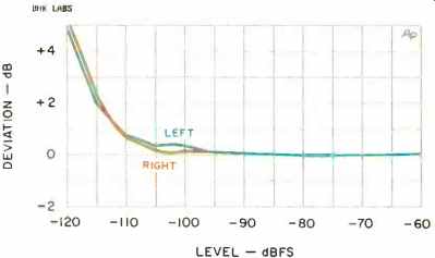
Fig. 4--Deviation from linearity.
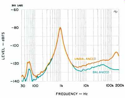
Fig. 5--Noise analysis for a 1-kHz signal at-80 dBFS.
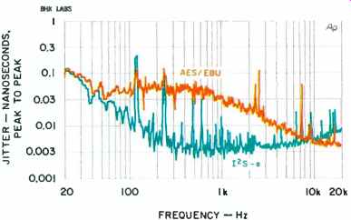
Fig. 6--Jitter spectra for 125-e and AES/EBU inputs.
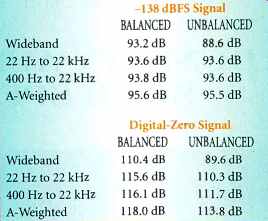
Table 1--Worst-case S/N ratios.
-----------
-------------------------
Associated Equip.
Equipment used in the listening tests for this review consisted of:
CD Equipment: PS Audio Lambda Two Special and modified Sonic Frontiers SFT-1 CD transports, Genesis Technologies Digital Lens anti-jitter device, and Classé Audio DAC-1 D/A converter Phono Equipment: Kenwood KD-500 turntable, Infinity Black Widow arm, Win Research SMC-10 moving-coil cartridge, and Vendetta Research SCP2-C phono preamp Additional Signal Sources: Nakamichi ST-7 FM tuner, Nakamichi DR-3 cassette deck, Technics 1500 open-reel recorder, and Denon DMD1300 MiniDisc recorder Preamplifiers: DGX Audio DDP-1, Sonic Frontiers Line-3, Ayre Acoustics K-1, and author's custom passive volume control and signal selector with phono preamp Amplifiers: Lamm Audio Laboratory M2.1 mono hybrid amps, Quicksilver Audio M135 and Sonic Frontiers Power-3 mono tube amps, and Audio Note Conqueror and Bel Canto SET 40 single-ended stereo tube amps Loudspeakers: B&W 801 Matrix Series 3s and Lowther PM5A drivers in Lowther Club Medallion II cabinets Cables: Digital interconnects, Illuminati DX-50 (AES/EBU balanced); analog interconnects, Transparent Cable MusicLink Reference (balanced) and Tara Labs Master and Music and Sound (unbalanced); speaker cables, Transparent Cable MusicWave Reference and Audio Note Custom
-------------------------
Use and Listening Tests
When I first received the Sonic Frontiers Processor 3, I hooked it up in my normal CD setup. Right from the beginning, I was very impressed with the sound and thought it was more lifelike than that of the Classé Audio DAC-1, one of my longtime favorite D/A converters. The Processor 3's definition, clarity, and spaciousness all struck me as superior.
Next, I replaced my PS Audio CD transport with the modified Sonic Frontiers SFT-1 so that I could hear how the Processor 3's AES/EBU and I2S-e connections compared. The I2S-e connection did improve transparency, detail, and spaciousness, but the differences weren't large.
However, this precluded my using the DGX Audio digital preamp (which provides EQ for my B&W speakers) or any other ancillary digital components that have only the common types of digital connections.
The Sonic Frontiers Processor 3 performed flawlessly in my lab and in my listening room. Not only was its measured performance superb, it also gave me the best digital sound I've heard in my home system. Needless to say, I very much enjoyed its stay in that system, and I enthusiastically recommend it.
(Adapted from Audio magazine, July 1998)
Also see:
Sonic Frontiers SFD-2 D/A Converter (Jan. 1995)
Sonic Frontiers Power-3 Mono Amp (Aug. 1996)
= = = =