Manufacturer’s Specifications
Preamplifier
Frequency Response: Line inputs, 1 Hz to 500 kHz, +0, —3 dB; MM and MC phono inputs, RIAA, 20 Hz to 20 kHz, ±0.2 dB.
Maximum Output: 10 V.
THD (New IHF Standard): 0.005%.
TIM Distortion: 0.0022%. Phono Input Sensitivity: MM, 0.5 mV; MC, +26 dB setting, 0.025 mV; MC, +32 dB setting, 0.01 25 mV, all for 0.5-V output at 1 kHz.
Phono Input Overload: MM, 300 mV; MC, +26 dB setting, 15 mV; MC, +32 dB setting, 7.5 mV.
S/N Ratio: 82 dB, A-weighted, for 5- mV signal at MM input.
High-Level Sensitivity: 31.5 mV. Phono Input Impedance: MM, 47 kilohms paralleled by 150 pF; MC, 10/30/100 ohms, selectable.
Dimensions; 18-7/16 in. (468 mm) W x 6¾ in. (171 mm) H x 15-9/16 in. (396 mm) 0.
Weight: 39.8 lbs. (18.1 kg).
Price: $3,550.00. [1984]
Amplifier:
Power Output: 300 watts rms per channel, 8 ohms. (For other ratings, see Table 1.)
THD: 1 to 2 ohms, 0.02%; 4 to 16 ohms, 0.01%.
IM Distortion: 0.01% at rated output.
Frequency Response: 0.5 Hz to 250 kHz, +0, -3 dB, for 1-watt output at maximum level-control position.
S/N Ratio: 125 dB, A-weighted, with inputs shorted.
Damping Factor: Stereo, 300; mono, 150, both at 50 Hz into 8 ohms.
Input Impedance: Unbalanced, 20 kilohms; balanced, 600 ohms, switch-selectable.
Input Sensitivity: High-impedance setting, 2.0 V; low-impedance set ting, 1.0 V; bridged mono, high-impedance setting, 1.83 V; bridged mono, low-impedance setting, 0.91V.
Dimensions: 18 in. (480 mm) W x 91/s in. (232 mm) H x 18¾ in. (476 mm) D.
Weight: 84.7 lbs. (38.5 kg).
Price: $3,550.00.[1984]
Company Address: c/o Madrigal Ltd., P.O. Box 781, Middletown, Conn. 06457.
Accuphase’s P-600 amplifier and C-280 preamplifier, the company’s flagships, offer knockout cosmetics with high performance to exacting specifications. Their designs do not follow the American high-end audio trend towards minimalistic circuit topology and few user controls. Rather, these two products have an unusual level of circuit complexity and control flexibility. No fewer than 11 power ratings are listed for the amplifier, including a rating of 450 watts per channel into a 1-ohm load! High performance is most certainly the name of the game here—but not without a few quirks, which became evident during our testing procedures.
 --
--
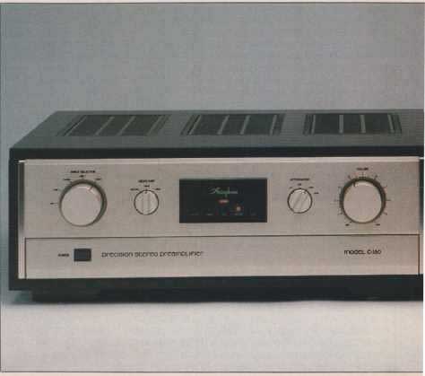
Preamplifier Layout
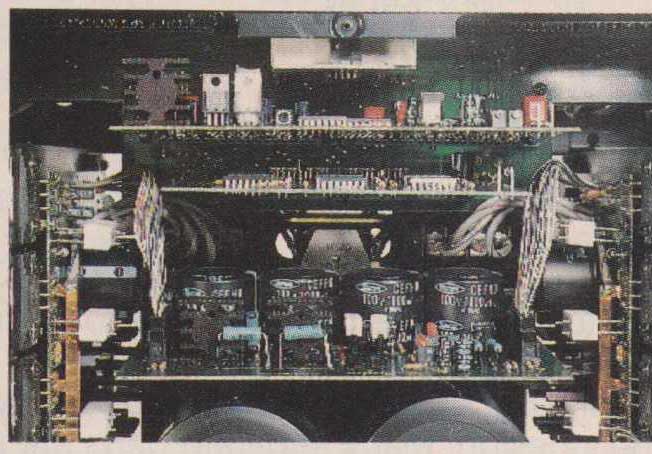
The C-280 preamplifier comes in an imposing 39-pound chassis with a visually stunning, persimmon-finished wood exterior. The wood has a glossy finish and lovely grain with a unique reddish-black, ebony-mahogany color. Underneath the wooden housing, aluminum sheet-metal panels form the sides, front, and rear of the chassis. The front panel and hinged access door are gold-anodized extrusions bolted to the chassis. Additional sheet-metal channels support the two power transformers and a large motherboard. The assembly is quite rigid, with good support for all heavy components, and service accessibility is maintained. Self-tap ping screws are used, which could leave small metal particles inside the chassis, although none were found.
At first glance, the four controls on the C-280’s faceplate make it resemble a minimalist preamp design. The push-to-open subpanel door, however, drops down to uncover switches for a.c. power, subsonic filter, and mono/stereo mode. These are followed by selectors for moving-coil input impedance, tape monitor, and tape-output defeat, as well as gain trimmers for each channel and a two-position Compensator” (loudness) selector. When the subpanel is closed, all that remains are two large rotary controls, for source selection and volume, which bracket rotary switches labeled Head Amp” gain (“Off/MM,” +26 dB” and “+ 32 dB”) and Attenuator” (full mute, attenuation “Off,” “—20 dB” and “—30 dB”). A central window above the subpanel has red LED status displays for a.c. power, loudness compensation, high-pass filter, mono mode, tape monitor, and record out. Tone controls have been eliminated, Accuphase’s only concession to minimalism. The C-280’s rear panel features seven inputs (two phono, three line, and two tape) and four outputs (two tape and two main) with an additional XLR output jack, rated at 600 ohms impedance, for each channel.
LEDs confirm the settings of all pushbutton switches, and a nonvolatile (battery backup) logic circuit stores the set tings when the unit is off. All controls, except for the volume and gain trimmers, activate relays. An effective mute circuit operates for 1 S each time a selector is changed. The detented controls, ticking relays, status indicators, and muting produce a feeling of precision when operating the Accuphase C-280.
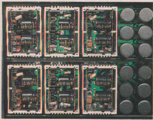
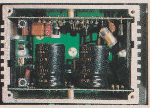
Internally, a total of 14 smaller circuit boards plug vertically into the motherboard. This profusion of circuit boards provides the necessary surface area to house the 225 transistors, 16 FETs, 33 ICs, and 167 diodes used in the C- 280’s design. Many separate parts are used, as if complex IC op-amps were being synthesized from discrete transistors on every p.c. board. One of these boards, holding 21 reed relays, runs parallel to the rear panel to control pro gram selection as close as possible to the input/output connectors. Relays are sealed inside pressurized nitrogen- gas housings and utilize either gold-plated or silver-palladium alloy contacts. Just behind the front panel sits the relay- controlling logic board with its nickel-cadmium battery backup system. In between these upright boards are six extruded aluminum-chimney amplifier modules, each housing two small circuit boards. Small LEDs, used as voltage- dropping diodes for setting bias, glow inside the boxes like tube filaments. The C-280’s three gain stages—a pre-pre amplifier, phono amp, and line amp for each channel—are assembled from these modules.
The C-280’s dual power supplies maintain this separation of function. Separate transformers for each channel have three center-tapped windings feeding 24 rectifiers and 12 filter capacitors. This gives separate unregulated d.c. lines for each of the six amplifier modules. Final d.c. regulation in this unusually complex power supply is performed inside the amplifier modules.
Every element of the C-280’s construction is superb. Circuit boards are glass-epoxy, 0.002- and 0.031-inch thick, with finished edges. Signal traces, solder mask and component designations appear on both sides. Soldering quality is excellent, and the extensive hand wiring is done with skill and care. Low-loss, foam-core coax running between the C-280’s input relays and low-level modules is soldered cleanly (foam’s low melting point has resulted in sloppy wiring in other audio components). Some internal wiring ends in multi-pin circuit-board connectors which are all gold plated. It is refreshing and unusual to find high-end units having gold plating inside, rather than only on the external connectors where the customer will see it.
Preamplifier Circuit Highlights
Each of the six modules in the C-280 employs a dual-differential input stage which feeds a common-base, complementary push-pull Class-A output amplifier in cascode connection. A d.c. servo-control IC is incorporated in each of these amplifiers to allow the C-280 to be d.c-coupled, from moving-coil phono input to main output, with negligible d.c. offset.
The line amplifiers are duplicated, with polarity inversion, to produce balanced outputs, ostensibly to allow for low noise pickup over long cable runs to the amplifier. While this could be useful in hostile environments, Accuphase’s selection of a 600-ohm output impedance for the C-280 preamp and the P-600’s 600-ohm input impedance (at their balanced XLR connectors) is based on a Bell Laboratories/ Western Electric standard, developed in the ‘30s, for use with telephone transmissions. Although present-day professional audio equipment utilizes balanced lines, professional line outputs are designed with much lower output impedance (on the order of 50 ohms) so they can drive multiple amps without loading losses.
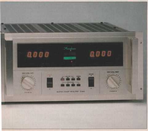
Amplifier Layout
The P-600’s great size and weight are very impressive; its 99-pound shipping weight far exceeds current United Parcel Service limits. This power amp, therefore, must be shipped by a freight service. The front panel is flanked by massive handles and a rack-mount frame. A large window provides multicolored status readouts: A large, digital peak- power display for each channel, running from 0.001 to 999 watts; a set of blue display-hold-time indicators, and LED status annunciators for each channel (‘Bridge Connection,” flashing power-display “Reset Indicator,” and “Load Impedance”). The display is bright and, set against the panel’s black background, is easily visible across a brightly lit room.
Below the display window, the P-600 has large rotary knobs, styled like the C-280’s, controlling “Input Level” to left and right channels in calibrated steps from 0 to —30 dB (and then off). At panel center, large “On/Off” switches for “Power” and “Speakers” flank two rows of small pushbuttons. The upper row’s controls display “Hold Time” (“Off,” “3 Sec’ or “30 Mm”) and the “Subsonic” filter (10 Hz, 12 dB/ octave). The lower row sets the range of the digital display (x1, x0.1, x0.01, and x0.001).

Fig. 1—Partial schematic of P-600 amplification stages.
On the test bench, with more than 1,500 watts being dissipated, the P-600 amp was only slightly warm, and totally silent.
The back panel features selector switches for choosing stereo or bridged mono operation, normal (2 to 16 ohm) or low-impedance (1 to 2 ohm) operation, power-display impedance (to yield power readings based on 2-, 4-, 8-, or 16- ohm loads), and balanced (600-ohm) or unbalanced inputs. The unit’s nonstandard binding posts will not accept dual or single banana-plug speaker-cable terminations. (Unfortunately, these posts also eliminated using the very convenient Monster Cable locking speaker connectors favored by co-author Greenhill.) A circuit breaker, switched and unswitched a.c. outlets, RCA phono and XLR input jacks, and a non-detachable a.c. line cord with a two-pronged plug— somewhat undersized for a high-current amplifier (30 amps/channel)—make up the remainder of the back panel.
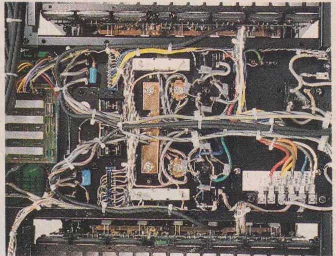
Like the C-280, the P-600 chassis achieves its strength and accessibility from a complex sheet-metal structure fastened together with self-tapping screws. Mechanical construction quality is first-rate, but the use of self-tapping screws in an expensive amplifier with many heavy parts seems out of place. Externally, the P-600 has a lightweight, gold-colored, extruded-aluminum frame. This serves mainly to dress up the chassis and provides mounting points for the removable sides, top and bottom. Internally, the expected massive heat radiators for the 28 output transistors run vertically, parallel to the side covers. From front to back, between the heat radiators, is a heavy “U” section that carries the transformer and other heavy power-supply components.
Most amplifiers conduct heat from the output devices to the entire chassis to radiate heat effectively. The P-600 exterior, however, always runs relatively cool because it relies only on internal radiators and the air passing through them via the liberally vented top and bottom covers. On the test bench, with more than 1,500 watts being dissipated, the P-600 remained slightly warm to the touch and totally quiet. (We have not yet found any fan-cooled amplifier quiet enough for listening-room use.)
The main amplifier p.c. boards run vertically, parallel to the heat radiators. Each channel’s 14 power transistors, two MOS-FET drivers, and thermal-sensing diode are mounted to the heat radiators, with all leads attaching to the top and bottom edges of the circuit boards. To replace a small part on the board, half of these components would need to be removed for the board to be swung away. Flat copper bus bars parallel the groups of seven transistor collectors and emitter resistors. The power-supply and output lines are soldered to the board but terminate in ordinary quarter-inch push-on connectors at the chassis. Hot-running components are held above the board by insulating spacers, although the P-600 amp has a few electrolytic capacitors (rated at 85° C) placed only 1/32-inch away from hot-running emitter resistors. Other capacitors in the P-600 were rated at an unusually high 105° C.
Several other circuit boards—for the metering, logic and power-supply regulation functions—are seated near the front and rear panels. Two of these circuit boards, positioned vertically just behind the front panel, handle the digital power-meter system (using a 12-bit ND converter and a 4-bit microprocessor) and logic control for switching of impedance ranges.
The P-600 has many pro” features, but it is rather expensive for most professional applications and also fails to meet pro standards in other ways. For instance, the ‘rack-mount” flanges cannot be used to mount the amplifier. Not only does the manufacturer warn against this installation, but the mounting holes are round, not oval or notched, as demanded by EIA rack specs. The front plate is held to the chassis with four small self-tapping screws, and the unit’s heavy toroidal transformer sits at the back of the chassis, not behind the faceplate (where it could be best supported by rack mounting). The rack-mount flanges are obviously a styling gimmick to evoke a “heavy-duty” image. Such gimmicks are not necessary: The P-600 is a lavish home amplifier, and we would prefer that it look like one.
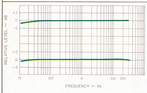
Fig. 2—RIAA response of C-280 preamp for MC at +32 dB setting (top curve) and
MM (bottom), for 0.5-V out at tape output.
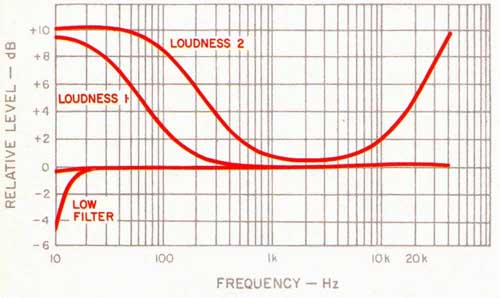
Fig. 3—Characteristics of preamp loudness and filter controls. From top
to bottom: Loudness compensation setting 2 (note treble and bass boost),
loudness setting 1 (bass boost only), flat response, and subsonic- filter
curve.
The P-600’s meters are beautiful to observe but are more entertaining than helpful. For power-amplifier use, a clipping or distortion light—which this amp lacks—is the single most valuable indicator. The meter peak-hold system is annoying:
When it is switched on, the meter is reset to 0 every 3sec. or 30 minutes (depending on the “Hold Time” selected), with only higher readings registering between resets. If the 3-S period is chosen, the “Reset Indicator” LEDs flash so frequently that they may be easily confused with clipping indicators, even when the amplifier is not clipping. Given the peak-hold and reset action of these meters, it might be better if each new peak reading started a new 3-S interval till reset, so one would always have time to read each update. The 30-minute hold time (intended to show the peak cutting level on one side of a record) does stop the flashing, but, with the meters storing the highest peak in the past half hour, they effectively cease to function in real time.
The P-600’s digital power meters do not sense power (voltage times current) but voltage alone. Their power calibrations are based on the assumption that what is being driven is a 2-, 4-, 8- or 16-ohm resistive load, not the more complex reactive loads of actual loudspeakers. The voltage is sensed before the P-600’s output-isolation network, which slightly degrades meter accuracy at high frequencies. The meters, though labeled “Peak Output Power,” are not peak- power indicators, nor do they read the rms value of peaks. Instead, they have a time response requiring approximately 6 mS of continuous sine waves to achieve an accurate reading. This approximates the BBC or European PPM (peak program meter) standard. For example, using single- cycle sine-wave pulses, 200 Hz was the highest frequency the meters would measure accurately. At 2 kHz, they read 70% of actual single sine-wave power, and at 20 kHz, only 6% of actual power. They were found to be accurate to within 5%, not outstanding for such an elaborate meter design.
Amplifier Circuit Highlights
The P-600 features a very rugged seven-parallel complementary bipolar push-pull output stage, for a total complement of 28 output devices rated at 200 watts of dissipation each. Figure 1 is a partial circuit diagram, in which 019 to 032 form the output stage of one channel.
Output-stage rail voltage levels are determined by a user settable impedance range switch, backed up by an auto- switch circuit (not shown). Either switch drops the d.c. rails from 82.5 to 44.5 V. This lower voltage limits high power dissipation when driving 1-ohm loads. (The Apt 1 amplifier uses a similar transformer-switching design to drive low- impedance loads.) A pair of small relays adjacent to the transformer perform the actual switching. They are tripped by a current-sensing circuit or the rear-panel switch. Bias current on the output devices does not change when the amp is switched to the low-impedance position, and we found no evidence of crossover notch distortion or any change in subjective sound quality at the lower setting.
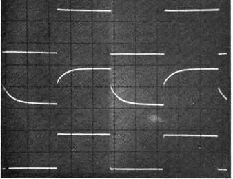
Fig. 4—-Response of preamp to 1-kHz square waves with inverse RIAA equalization
through MC input (+32 dB setting). From top to bottom: Generator output before
equalization, signal at preamp’s tape output with no input filtration, and
signal at tape output after 200 filtration of input signal (see text). (Scales:
Vertical, top trace, 1 V/cm; vertical, middle and bottom, 0.5 V/cm; horizontal,
0.25 mS/cm.)
A series of additional protection circuits, including VI limiting, cuts drive to the output stage or disengages the massive speaker relays if d.c. offset is detected. User resettable ac-line circuit breakers are employed instead of fuses. Power-supply parts, as well as the owner’s household circuit breakers, are protected by a turn-on inrush-current surge limiter circuit. Resistors in series with the line limit turn-on current; when the filter caps are nearly charged, relays short these resistors.
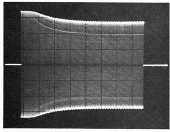
Fig. 5—Amplifier response to 400-mS burst of 20-kHz, at level just below
clipping, into 4-ohm load. Note shrinking power envelope as mutual conduction
begins, as well as horizontal lines (beginning at 25 mS) indicative of “sticking.”
(Scales: Vertical, 20 V/div.; horizontal, 50 mS/div.)
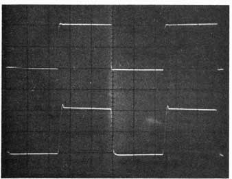 Fig. 6—Amplifier large signal response to 20 square wave, driving 8-ohm
load: Input signal (top) and P-600 output (bottom), 312 watts/ channel (Scales:
Vertical, top trace, 1 V/div.; vertical, bottom, 50 V/div.; horizontal, 10
u.S/div.)
Fig. 6—Amplifier large signal response to 20 square wave, driving 8-ohm
load: Input signal (top) and P-600 output (bottom), 312 watts/ channel (Scales:
Vertical, top trace, 1 V/div.; vertical, bottom, 50 V/div.; horizontal, 10
u.S/div.)
The drive current requirements of such an output stage could reflect back through bipolar drivers to adversely load the input differential amp. The P-600’s power MOS-FET drivers neatly solve this problem, since these drivers require practically no drive current themselves. They do demand high drive voltages, however, and this is provided by a regulated extra-high-voltage supply and a Darlington/cascode pre-driver stage, shown as 011 to 016 in Fig. 1. A Darlington circuit is formed by 011 to 014, providing a high input impedance.
The dual-differential amplifier input circuit uses FET and bipolar transistors. It is formed by the 01 to 02 differential-amp FETs, the 03 to 04 circuit, and the 01a, 03, 02a and 04 cascode amplifier. Conventional signal negative feed back is supplemented by a low-frequency servo amp” for d.c. stability. A differential input is provided, with profession al XLR connectors, but is off the mark with its low 600-ohm input impedance. A 10-kilohm input impedance would have been more useful.
Preamplifier Measurements
All gain measurements were somewhat lower than those claimed by Accuphase, perhaps signifying that the manufacturer measures the C-280’s voltage gain from input to output without using the IHF-specified standard source impedance. (For example, the C-280’s MC input gain measured 6 dB less than claimed, because the preamp’s 100-ohm maximum input impedance loads the 100-ohm IHF source by 6 dB.) Gain from phono in to main out, including the line amps, ranged from +50 dB for moving-magnet phono to + 76 dB for moving coil (at the + 32 dB MC setting). All measurements of output level, noise, and distortion confirmed the high level of performance claimed by the manufacturer.
The C-280’s frequency response measurements are just as impressive. Deviation from the true RIAA response was ±0.1 dB (our measurement resolution), 20 Hz to 20 kHz, for all phono inputs (Fig. 2). Although no tone control circuitry is used in this Accuphase preamp, Fig. 3 shows the low- frequency boost provided by loudness control position 1, the additional high-frequency boost from position2, and the sharp skirt of the very effective 18 dB/octave subsonic filter used to prevent rumble from reaching the rest of the system.
Phono overload for the MM inputs was a very high 350 mV. The MC input’s overload points were lower, in proportion to the pre-preamplifier gain selected (i.e., 35.0 and 17.5 mV for the +26 and +32 dB positions). This indicates that, at 1 kHz, the pre-preamplifier has more headroom than the RIAA section that follows, as it should.
At very high frequencies, where the RIAA feedback equalization reduces the phono section’s gain, the unequalized pre-preamplifier section overloads first. This condition is shown in Fig. 4. The top trace is the 1-kHz square-wave generator’s output, which is fed through a precision inverse RIAA equalizer to produce a signal (not shown) having very high positive and negative spikes. This corresponds to the output of an ideal phono cartridge playing back an ideal recorded square wave. Although the 1-kHz sine-wave output of this source is well within the headroom limit of the MC input at the +32 dB setting, the narrow spikes from the equalized square wave overload the pre-preamplifier. It does not recover for about 0.25 mS. When this distorted signal passes through the RIAA stage, it emerges with a rounded edge, as shown in the middle trace of Fig. 4.
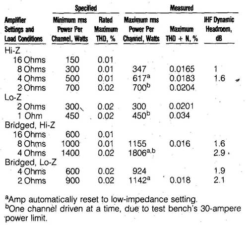
- - -Table 1—P-600 amplifier power performance (output before clipping,
20 Hz to 20 kHz).
Amp automatically reset to low-impedance setting.; One channel driven at a time, due to test bench’s 30-ampere power limit.
If the designers had restricted the bandwidth of the pre preamplifier to 200 kHz, the nearly perfect square wave shown at the bottom of Fig. 4 would have resulted. Here, bandwidth limiting would produce a “faster” preamp, bizarre as that may sound. Perhaps even a mistracking MC cartridge might not produce sufficient high-frequency noise to overload this wideband pre-preamp, but when combined with r.f. interference, audible distortion might result. Possible engineering solutions include bandwidth-limiting the C- 280’s pre-preamp stage or the use of a high-gain RIAA feedback circuit which would connect directly to an MC cartridge without the intervening amplification stage. The owner can opt for a transformer step-up, which has, in practice, no input-overload problem.
Amplifier Measurements
The P coasted through the FTC’s one-hour, one-third- power preconditioning at 8 and 4 ohms without thermalling out. The front panel became only slightly warm because it is not thermally connected to the heat radiators.
Though this amplifier is rated at 300 watts per channel, the actual steady-state power output easily exceeded the manufacturer’s specifications, as shown in Table I. The power supply did not perform like an ideal voltage source (allowing the amplifier to double its power output each time the load impedance was halved), but the P-600 was still able to deliver large amounts of power into low impedances. Accurate testing of this amplifier required the services of a very substantial Variac to maintain line voltage at 120 V. For the 2-ohm stereo and the 4-ohm bridged mono measurements, it was necessary to test only one channel at a time, because our test bench setup could deliver only 30 amps continuous; the P-600 was still not taxed, but our power lines were!
Unlike the C-280 preamp, the P-600’s large signal output of 300 watts allowed for distortion measurements far above the noise floor. Signal-to-noise ratio, sensitivity, and maximum THD plus noise readings (20 Hz to 20 kHz) confirmed the manufacturer’s specifications. The P-600 provided 27.8 dB of signal gain, higher than the standard 26.0-dB gain found in most other power amps. As shown in Table I, measured THD plus noise exceeded the ratings very slightly during tests of the amp’s low-impedance operation. There, the P-600 showed maximum THD + N ratings of 0.021% for 300 watts output into 2-ohm loads and 0.034% THD + N for 450 watts output into 1-ohm loads.
Small-signal, high-frequency response of the amplifier extended from 5 Hz to 170 kHz for a 1 -dB roll-off with 8-ohm loads, down only 2.0 dB by 250 kHz, well within the specifications. The frequency response varied slightly with the loads, the 1-watt high-frequency —3 dB down point being over 350 kHz into 8-ohm loads, 170 kHz for 4-ohm loads, 125 kHz for 2-ohm loads and 70 kHz for 1-ohm loads.
The P-600 amplifier proved stable with both inductive and capacitive loads, with no reduction of maximum rated power when a 2- capacitor was connected across the 8-ohm load in each channel. The 300-Hz clipping test showed excellent performance: The amplitude of harmonics fell as their frequency went up, and, in addition, there was little sign of line harmonics or line-frequency modulation products.
On the other hand, there was at least one condition which could cause the amplifier difficulty, as shown in Fig. 5. With a test signal consisting of a 400-mS burst of 20-kHz sine waves, at a level just under clipping into a 4-ohm load, the amplifier starts out with its power-supply capacitors fully charged, and approximately 560 clean watts (500 rated) available. After about 25 mS, however, the capacitor charge diminishes, and clipping begins. This puts the output stage in a state of mutual conduction, with the complementary halves of the output section conducting current simultaneously, thus working against one another and behaving like a partial short circuit across the power supply. More power is then consumed, further aggravating the condition (25 to 200 mS). Evidence of the struggle is seen in the decreasing clip level and the horizontal “sticking” lines below the clip level. By 200 mS of the tone burst, current draw from the power line rises from an initial value of 11 amps to about 25 amps, and line voltage falls. If the tone is not cut oft at 400 mS, the P-600 hums loudly and eventually switches automatically to the low-impedance transformer- tap position.
When driven by 20-kHz sine waves with even slight clip ping, the P-600 shows signs of “sticking” (an amplifier’s tendency to continue clipping after the input signal has fallen back below the level which would normally make it clip) and mutual conduction at the same time. In fact, this latter condition limits the P-600’s high-frequency power bandwidth (—3 dB or half-power frequency) to 100 kHz. Mutual conduction occurs at 2 S/cycle about 10% of the time during clipping at 20 kHz. At the lower frequencies, more typically found in music, it will happen less often. Many power amps with bipolar transistors have this tendency. Although the condition could shorten output-transistor operational life, the large output stage of the P-600 promises long, trouble-free life in normal use.
Figure 6 shows the large-signal rise-time, which was measured at a very fast 2.0 uS. The maximum slew rate was 50 V/uS (symmetrical). The measured HF slew factor, when rating the amp at 300 watts into 8 ohms, was 5. Figure 6 illustrates the P-600’s square-wave response for a 20-kHz input signal driving the amplifier to just below clipping. The leading edge shows a small amount of overshoot, with a slight bit of rounding on the trailing edge. Both are within 10% of the square wave’s period, indicating artifacts only above 200 kHz—an excellent performance.
Use and Listening Tests
In operation, this combination of preamp and powerful amplifier is as docile as a table radio. Thanks to elaborate relay circuitry, there is never a turn-on or turn-off thump, no mechanical 60-Hz buzz from the three power transformers, and no annoying noise from a cooling fan. Even the amp’s turn-on surge drawn from the power line is minimized by a slow charge and relay shunt circuit, so house lights do not flicker when the P-600 is clicked on.
The only difficulty in using the C-280/P-600 combination is finding a place large enough to put it. Installation requires a large, well-supported area for the two units, about 38 inches wide and 24 inches deep. This space must also permit unrestricted airflow to the power amp, support the combined 124 pounds of weight, and allow the preamp’s beautifully finished cabinet to be seen. After setup, these units proved to be unequaled attention getters, looking powerful and expensive. The large controls, digital display (on the amplifier), and clear markings invite knob-twiddling and button-pushing.
How do these Accuphase components sound? Their wide dynamic range made the most memorable first impression. The greater-than-normal gain in both preamp and amp intensify this effect, and also make the loudness compensation boost the frequency extremes more than usual. The P 600’s power reserves allowed co-author Clark to get clean, undistorted sound from his highly efficient reference monitors even at 11 7-dB levels—louder than acoustic instruments playing in a concert hall, though still not as loud as a real drum set playing 10 feet away. The great dynamic range of Compact Discs could also be appreciated. With the P-600 driving Greenhill’s modified Dahlquist DQ-10s, nominally rated at 4 ohms impedance, its meters jumped from 2 to 840 watts during the explosive entrance of the firebird on the Telarc CD of Stravinsky’s the “Firebird: Suite” (CD-80039). This sonic peak possessed a degree of transient speed and dramatic attack not heard before. It was clean and undistorted, with a striking vividness, vitality and power. Even small loudspeakers, rated for less powerful amplifiers, came alive with so much available power. At milliwatt levels, the amp/preamp’s resolution of detail at low volume was outstanding, rendering the full resonances of Willie Nelson’s throaty tenor on Columbia’s exceptional Compact Disc, Always on My Mind (CK37951).
The P-600 amplifier was run in a number of gain-matched open comparisons with Greenhill’s reference amplifier. Both amps demonstrated excellent depth of imaging and retrieval of instrumental resonance, as well as rendering a rich, full bass at both ends of the power range. The P-600 showed a wider and deeper sound-stage image and a slight boost in the warmth region.
The preamp was compared subjectively to Greenhill’s reference solid-state preamplifier, which has a gain structure similar to the C-280’s but an MC phono input load impedance higher than the C-280’s 100 ohms. Using the F- 600’s meters, the two preamps were gain-matched to a test record (played using a Marovskis MIT-i MC cartridge). After lifting the MC pickup off a record, both preamps were dead quiet. Sonically, the Accuphase proved to be slightly brighter, less dynamic, and not as revealing of instrumental resonances. The reference preamp also had slightly better depth of imaging. Crossovers and other electronics could not be placed on or near the C-280’s cabinet without audible hum in the MC phono mode.
In another system, one C-280 preamplifier and two P-600 amplifiers were used, with an electronic crossover, to power separate sections of Apogee ribbon speakers. The amps, set to their low-impedance positions, drove the 1 .5-ohm (nominally rated) midrange ribbons and bass panels without difficulty. However, the Accuphase amplifiers and preamplifier sounded more detailed, but brighter and harsher, than the Krell KMA-100 amps and Mark Levinson ML-6A preamp normally used in that system.
The C-280 preamplifier and P-600 amplifier impress us as an unusually complex but highly competent amplifier system. The large number of electrical parts and the mutual conduction at clipping generate a few concerns about reliability, but the superb quality of parts and cool operation should ensure long component life. Overall, the Accuphase approach achieves high performance here through brute- force design—many quality parts with close tolerances, circuit redundancy, and extremely high power—rather than through engineering innovation. Accuphase’s conservatism relies little on cleverness or high-tech treatment of signal flow, circuit topology or individual parts. Overall testing revealed pre-preamp overload in the C-280 and mutual conduction in the P-600, but superb performance in all other bench tests.
The Accuphase P-600 and C-280 are true high-end audio components with stunning cosmetics, stringent specifications, and hot performance. Of the two units, the P-600 stands out. Sonically, it is an outstanding amplifier, capable of exceptional definition at all power levels. What Accuphase has created in the very powerful F-600 is the synthesis of microprocessor logic, extremely high current circuitry, and audio at all levels in a single chassis. The intermixed technologies are made to work together as if they were designed with one goal in mind.
Laurence L. Greenhill and David L. Clark [AUDIO/Aug. 1984]
[adapted from Audio magazine]