|
|
This box is a triple threat—mike preamp/mixer/ monitor—and brings you a giant step closer to experiencing the joys of recording live music. Also works great as phono preamp--perfect for PureVinyl LP digitization!
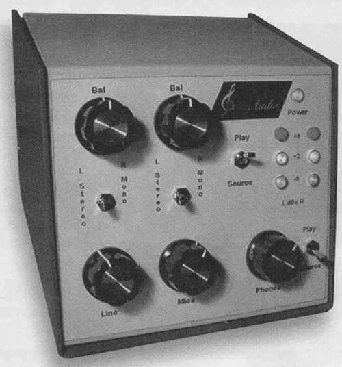
PHOTO 1: PM-2 preamp mixer/monitor.
Named the PM-2 (for preamp/ mixer/monitor), this component is designed for two recording applications:
1. Live music, with a "purist" or "minimalist" single stereo pair of microphones.
2. Transfer of pre-recorded music, e.g., on vinyl or tape, to a CD (or other medium), with the option of real-time voice dubbing.
OVERVIEW
For live music recording, the simplest audio path ("minimalist") includes only a stereo pair of mikes, with their pre-amps directly feeding the recorder. The PM-2 audio path (Photos 1 and 2) comprises a mike pre amp with line-level inputs summed into the output, if desired. (The line inputs could accept additional mike! mixer outputs, a band's PA feed, a direct electric bass signal and so on.) With a purely acoustic ensemble in a good-sounding venue, an optimally placed stereo mike can often provide astonishing clarity, detail, stage coherence, and spaciousness.
For transferring vinyl, tape, and so on to a CD, use the line inputs, but you can mix in an adjustable amount of mike signals, e.g., for voice announcements between songs, narration, or (for those so inclined) karaoke sing-along.
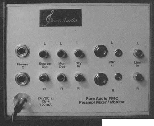
PHOTO 2: Rear panel.
FEATURES
1. Level and stereo balance controls, and stereo/mono switch, for mike and line channels.
2. Inputs for hi-z dynamic mikes, or electret mikes such as the (extremely high-quality) Mitey Mike II (designed by: Dr. Joseph d'Appolito and Richard Campbell). For such electrets, pure DC on the "rings" of stereo jacks allows remote ("phantom") powering.
3. High-quality headphone amp (outputs for two pairs switchable between the mixer output or an external signal (usually the recorder's playback) connected to the PM-2's jacks labeled "Play In." The phone amp can drive the high-sensitivity 300-ohm Sennheiser HD650 phones cleanly to 117dBSPL.
4. Monitor outputs for driving a stereo amp and speakers, independently switchable as above ("source" or "play").
5. Peak output level-indicating lights for -4, +2, +8dBu (0.7, 1.4, 2.8V peak).
Note: +8.24dBu = 2.00VRMS = 0dBFS = RedBook CD full scale.
If desired, you could label the level lights -12, -6, and 0dBFS.
In any case, the red lights indicate instantaneous peaks of ±2.83V, which is "brick wall" digital clipping on a CD, and should never be exceeded.
PREAMP/MIXER SCHEMATIC
I used a TL074 quad op amp (U1, A, B, C, D) for the audio (Fig. 1); you can substitute other op amps. But note that while the TL074 output stage is usually considered to be Class AB, the maximum signal current drawn here is less than that stage's bias, so it's operating in pure Class A.
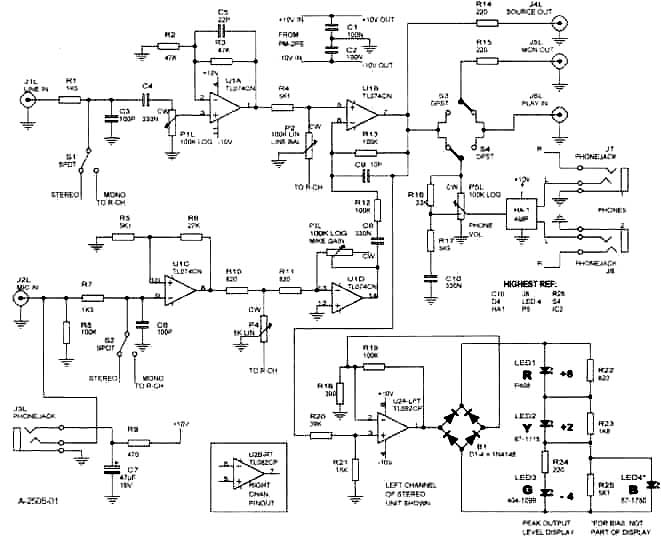
FIGURE 1: Preamp/mixer/monitor. Left channel of stereo unit shown.
The line input is RFI filtered, DC blocked, and attenuated by P1L, R (for left, right channel), then amplified x2 by U1A. With P2 (balance) set midway, the signal is reduced by half. This is fed to the non-inverting input of U1B, where the signal "sees" a gain of two because of R12, R13. Thus, the maximum gain (P1 up full) from line in to source out is 2 (+6dB).
MIKE CIRCUIT
The preamp (U1C, D) is admittedly not state-of-the-art in noise level with a 10k source (typical hi-z dynamic mike). With 24nV_/Hz equivalent input noise density, root-sum-squared with the 12.7nV_/Hz noise of a 10k-ohm source resistance, this source noise is increased by 6.5dB (the noise figure of the preamp with 10kg source).
However, dynamic mikes are not the best in fidelity for purist recording! I designed the PM-2 primarily for use with the Panasonic WM-60AY electret mike capsule (used in Mitey Mike II). I modified the capsule (more on this later) and incorporated a remote ("phantom") powered preamp, resulting in a sensitivity of 10mV/Pa and 53nV_/IHz noise density. The signal (and mike capsule noise) are thus amplified to a point where the PM-2 mike preamp's noise produces only a 0.8dB signal-to-noise ratio reduction (0.14dB with the Mitey Mike II because of its higher 25mV/Pa sensitivity), Using the WM-60AY with its incorporated preamp (it should be called a "pre-preamp" to distinguish it from the PM-2 preamp), and plugged into the PM-2, the "A" weighted noise floor is 32dB SPL, and the 2% THD point is 133dB SPL (much too loud for safe hearing!), resulting in a dynamic range of 101dB, 5dB more than the (sonically questionable) 96dB dynamic range of a CD.
The output of U1C is fed, through the balance control, into the inverting input of U then summed into (and polarity restored to non-inverting by) the output stage U1B. With P3L, H at maximum, and P4 (mike balance) mid way, the maximum 2nd stage gain is 47.3. With the input stage ( U1C) fixed gain at 6.3, the overall maximum mike channel gain is (measured at) 298 = 49.5dB.
This is quite a bit less gain than that of mike preamps on tape recorders, or preamps designed to capture the quietest sounds (bird songs, surveillance, and so on). But the PM-2 is optimized for music recording, where the average SPL may reach or exceed 110dB, with waveform peaks of 125dB. With maximum mike gain, the PM-2 with a Mitey Mike II will output 2V HMS (0dBFS on a CD) at 82dB SPL (Table 1). This is sufficient mike gain for any kind of live music; 82dB peak SPL corresponds to about 67-72dB average SPL, about that of quiet conversation.
INDICATOR LIGHTS
U2 (half of the dual op amp per channel) feeds an AC current, nearly proportional to the mixer output voltage, to diode bridge D1-4 (Fig. 1). Rectified, this current is fed to the series string of green, yellow, and red LEDs, each with threshold-setting resistors across them. The blue LED (4) acts as a voltage clamp for the green LED (3), helping maintain brightness balance of the three displayed LEDs (1, 2, 3). You must use the specified LEDs (available from Digi-Key) for correct thresholds and visibility balance.
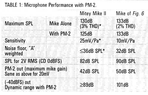
TABLE 1. Microphone Performance with PM-2
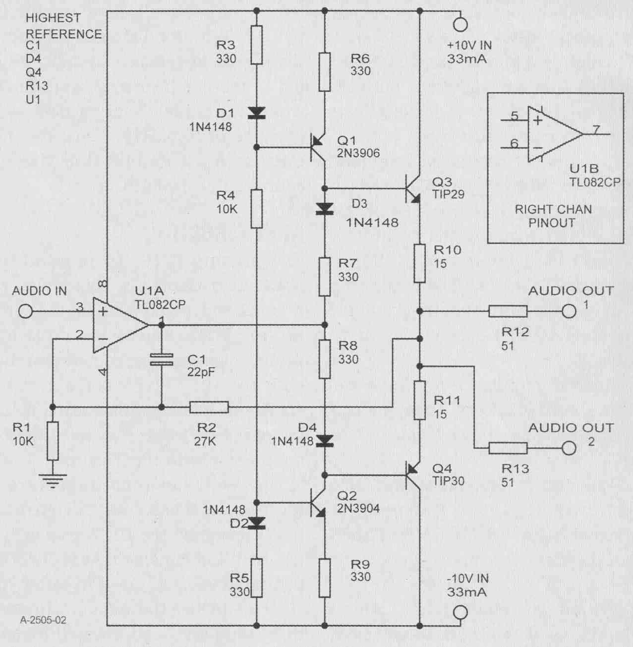
FIGURE 2: Headphone amp.
HEADPHONE AMP
Figure 1 shows the phone amp (HA-1) fed from a stereo 100k-ohm pot (P5L, H) with loudness compensation (10% tap, R16, R17, C10). The latter is effective but not "boomy," compensating down to about 70dB headphone SPL for low volume reduction in LF hearing sensitivity.
Figure 2 shows the headphone amp schematic. It's the same amplifier de scribed in my "A High Quality Solid- State Headphone Amp", except biased for ±10V supplies in stead of ±13V. Q3-4 are a unity voltage-gain power stage, operating in Class A with one pair of 300 ohm phones; with two phone pairs or 32-ohm phones, operation is Class AB at high power, but is still sonically distortion-free. With constant-current biasing (Q1, 2), the output stage drive current is less than the op amp's output stage bias, so U1 operates in Class A.
Frequency response of the overall amp is DC -230kHz (-3dB). The 51-ohm output resistance (from R12, 13) serves three functions:
1. Output is unconditionally stable.
2. Output is short-circuit proof.
3. Similar power is delivered to 300-ohm and 32-ohm phones (about 3dB more to 32-ohm phones, but they tend to be less power-efficient than 300-ohm phones).
Of course, you can use the PM-2 as just a headphone amplifier (feed your source player into the PM-2 line inputs) when not making recordings. And if you want to hear outside sounds (wife calling, phone ringing, elephant trying to get into swimming pool) while listening to loud headphone music, you can plug a microphone in and mix it into the music (and hear yourself singing along in private).
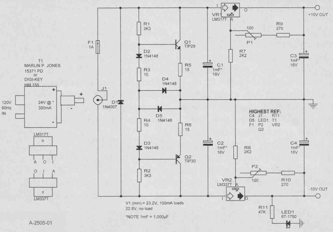
FIGURE 3: ±10V power supply for audio preamp/mixer/monitor PM-2. Maximum
output current: 250mA if balanced; 60mA imbalance (limited by Q1, Q2 circuit).
FWHK FE4823240D030. t at 100mA 120V RMS in Marlin P. Jones # 15371 PD Jack
dR. = +. Highest Ref. C4 D5 F1 LED P2 Q2 R11 T1 VR2.
POWER SUPPLY
To render AC line hum inaudible, use a “wall wart” external 24V DC supply (Photo 3). But the audio circuitry (Figs. 1, 2) needs a split bipolar supply (±10V regulated used here). So the incoming single-ended 26V (at the 100- 150mA used) needs a “DC center tap” to serve as circuit ground. You could use a series pair of resistors, but unless a small value (wasting a lot of current), the derived center voltage would be sensitive to positive versus negative supply load imbalance.
Q1, 2 provide a “stiff” (low impedance) center tap. Basically a Class AB amplifier output stage, the bases are biased equally above and below the single-ended input voltage’s midpoint (offset by D2, 3 and R3, 4 to compensate the base-emitter drops of Q1, 2, plus a little more to establish the Class AB bias current, stabilized by R5, 6). D4, 5 limit the voltage drive across the output transistors’ base-to-tap output points, in the event of a supply output-to-ground short, thereby limiting excessive ground current to protect Q1, 2.
A power op amp such as the LdV1675T can do this supply-splitting function (see National Semi’s app notes), but it’s not unity-gain stable, more components may be needed, and more bias current (than the circuit used here) may be drawn. D1 protects against reverse- polarity input DC (or an AC wall wart mistakenly used), and fuse F1 blows if all else fails. Following the supply splitter, conventional regulators and 4000uF of filter caps provide very clean ±10V supplies to the audio circuitry.
Important note: The DC input jack (not shown on schematic; power supply jack J1 on parts list) must be insulated from the enclosure chassis. To do this, I mounted the jack centered on a piece of ‘Ac” thick plastic sheet, about 1½” square, then attached this over the in side chassis surface, centered on a ¾” chassis hole (Photo 2). I fastened the plastic with CA glue, but this broke loose after a while, so I re-glued it, then beefed it up with epoxy. I recommend mounting screws, even though I was too impatient/lazy to use them.
CONSTRUCTION
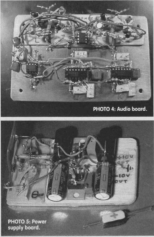
Photos 4-7
The enclosure I used is by LMB, part number UNC 5-6-6 (Digi-Key L159). It's attractive, painted textured blue and white, but possibly not large enough to accommodate a PC board holding all the parts. I needed to use two boards: the audio board (Photo 4) being solid copper with breadboard construction, mounted on the inside top of the cabinet, and a supply board (Photo 5)-a piece of balsa with parts glued on-mounted on the right side of the other cabinet half (the base). I used two- and three-pin connectors to connect the supply board to the DC input and the audio board, respectively.
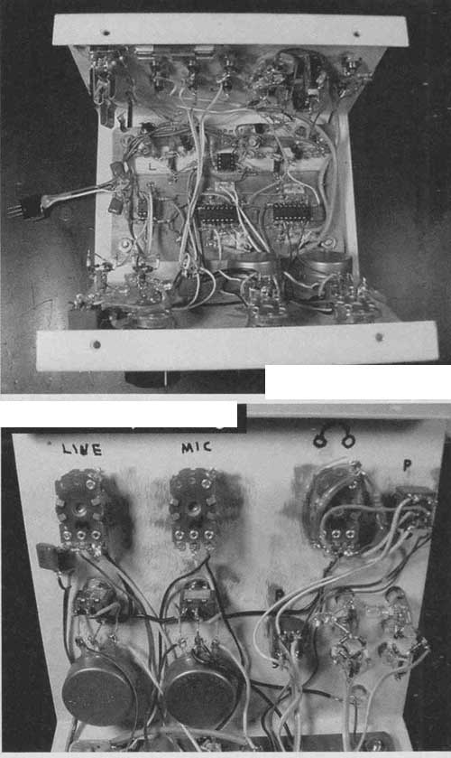
Depending on the size required for a real PC board, you might need a larger cabinet. Photos 6, 7, and 8 show my congested, impatient, Mickey Mouse wiring. Note that I didn't use the power transistors specified--I used OHS (On Hand Stock) units, but the phone amp and supply-splitter are very insensitive to transistor parameters. The T1P29 and TIP30 parts specified are well over rated for their jobs (Fig. 4).
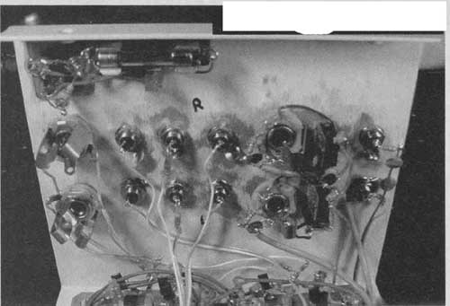
PHOTO 8: Rear panel wiring.
SCRAPE THAT PAINT
You must grind off the thick paint (on the cabinet type suggested) to bare metal surrounding all controls and switches, and audio jack mounting holes (you must ground the pot and switch shafts to avoid hum pickup, and so on). You could mount the audio board with screws, but instead, to avoid protruding screw heads aesthetically upsetting the nice smooth cabinet top, I:
1. Located the four board corner mounting hole locations on the inside cabinet top surface.
2. Ground off the paint on a ½" circle around the marked locations.
3. Silver-epoxied four ½" #6 machine screws' flat heads to the chassis. "Circuit Works CW2400" is a room-temperature curing conductive epoxy made by Chemtronics.
4. After that cured, I beefed up the joints by applying two-part epoxy around them.
This worked well-the joints have held up, and the screws are well-grounded, which with nuts and lockwashers clamping the audio board's solid copper ground plane, provide a very solid audio ground. I used, and recommend using, a layer of 1/8" thick balsa wood (or rubber sheet) between the board and chassis to prevent board flexure or possible rattling.
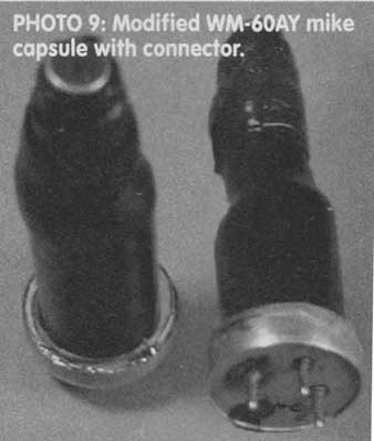
PHOTO 9
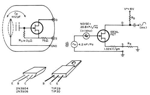
FIGURE 4: Transistor pinouts.
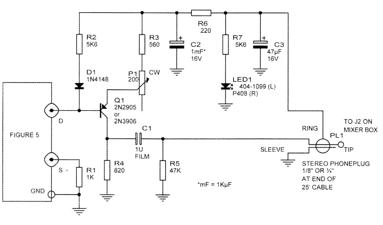
FIGURE 5: Panasonic WM-60AY electret mike. When the original connection between
S and gnd. is bro ken, nearly constant-current (300 ± 50uA over ext. Rs range
of 0- 20k-ohm establishes that Rg is returned to FET 5, not gnd. Circuit Model
Accuracy = ±1dB for sensitivity and noise (>1kHz) ca (4V <= V <=
10V)
MICROPHONE INPUT JACKS
I used (Photo 2) ¼" phone jacks for hi-z dynamic mikes, and 1/8" stereo jacks for electrets (+10V DC on the "rings"). I used 1/8” jacks (and plugs on my mikes) so neither mike type could be plugged into the wrong jack. But the ½" plugs and jacks I used are sometimes intermittent (117dB SPL transient blasts in the phones!), so I recommend ¼" stereo phone jacks for the electret mike in puts. If you plug a dynamic mike into the electret jack, the mono plug sleeve will short the 10V DC. But no harm is done; the 470-ohm resistor (Fig. 1, R9) will safely limit the short current to 21mA.
A HIGH DYNAMIC RANGE RECORDING MICROPHONE
The Panasonic WM-60AY (Photo 9, $2.64 from Digi-Key, P/N P9959) is used in Mitey Mike II. Its response is so flat (typical ±1dB, 20Hz-20kHz) that Stereophile uses a MMII for speaker measurements.
Figure 5 shows what's in the electret capsule, measured data, and a circular model. The internal FET source, after a 75-ohm resistor, is originally grounded. The MMII article describes how to break this connection, so that you can add an external source-to-ground resistor. This greatly increases the maximum SPL capability.
I modified this and mounted the capsules with heat-shrink tubing (careful-low heat!) to a 3-pin connector, which plugs into a receptacle at the end of a copper tube attached to a 3 ¼” x 2 ½"x 1 1/8" Bud box (Photo 10). The "mike wand" end of the box is covered with ½" thick foam rubber to prevent HF re-flections back to the mike. The bottom of the box has a standard receptacle for mike stands.
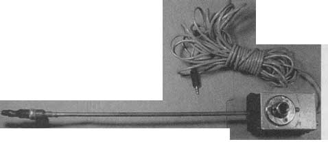 PHOTO
10: Mike assembly.
PHOTO
10: Mike assembly.
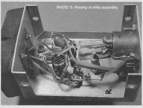
PHOTO 11: Preamp in mike assembly.
FIGURE 6: High-performance microphone. Low noise current-mirror preamp in
3 1/4" x 2 1/8" x 1 5/8" Bud Box,, attached to 13" x 1/4" O.D.
copper tube, "mike wand."
PHANTOM POWERED PREAMP
Figure 6 shows the preamp I built into the mike box (Photo 11). The circuit functions as a very linear current mirror, amplifying the mike sensitivity to 10mV/Pa. Maximum SPL (2% THD point) is 133dB. The preamp output impedance is 787-ohm), seemingly high.
But it takes 2460pF loading (82' of 30pF/ft. cable) to cause 0.25dB loss at 20kHz. This output topology, though, has advantages over a low-z emitter follower or push-pull op-amp output: no amount of capacitive or other loading will produce slew-rate, crossover, or other distortion. The output stage is basically a "solid-state single-ended triode." Unloaded, the preamp BW (-3dB) is 5Hz-1.7MHz. Driving 50' of 30pF/ ft. cable, 20kHz loss is only 0.1dB.
Both the preamp and (as configured) mike capsule have very high power supply rejection ratio PSHR so with the regulated and Ft-C filtered DC fed into one conductor of the two-wire + shield cable, you hear absolutely no AC line hum or crosstalk from the other stereo channel of the PM-2 mixer.
Figure 7 shows the noise spectrum of the mike and preamp. Table 1 shows the performance of this mike, and MMII, feeding the PM-2 mixer, With the mike of Fig. 6, maximum SPL (2% THD) is 133dB, corresponding to an average music waveform SPL of about 118-123dB, louder than a large rock band up close (and much too loud for safe hearing!). "A" weighted dynamic range of this mike/mixer combo is 101dB.
The Input Side of Things
Gammaelectronics deals almost entirely with music-playback technology. And as every reader knows, even with the best playback system in existence, the sound is at the mercy of the recording, so many of which use too many (and too close) mikes, not to mention the incessant addiction to processors (EQ compression, digital "enhancements," and so on) that engineers believe they need.
But when you cap ture (as opposed to "produce") your own recording of live music with a simple (but well optimized through much experimentation) minimalist mike pair placement, and a direct path to the recorder, then what you hear (on neutral play back equipment) is what was there.
TABLE: HIGH-PERFORMANCE MICROPHONE
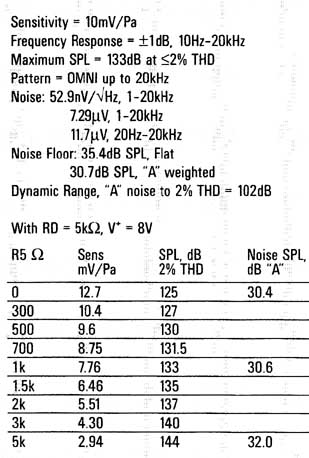
TABLE 2: PM-2 PERFORMANCE DATA.
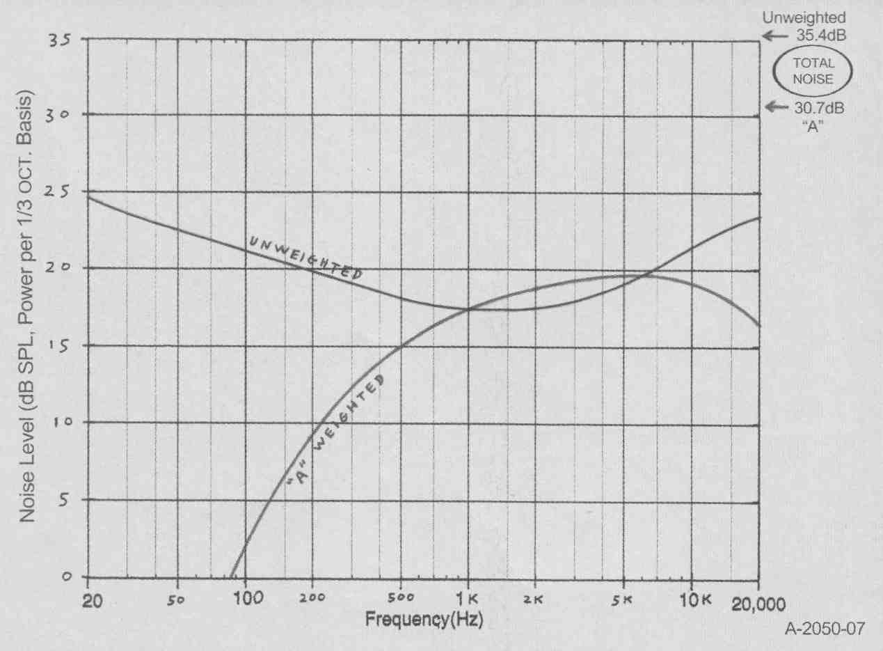
FIGURE 7: Noise level, WM-60AY mike and PM-2 MP preamp, 1/3 octave analysis.
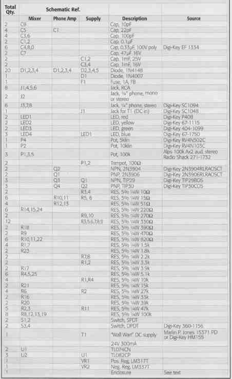
PM-2 Parts List
Then, if the music and its venue acoustics were very good, you'll have a recording that provides:
1. An accurate, undoctored reference to best evaluate your playback system's fidelity (you might learn more than you wanted to know, or you might be pleasantly surprised).
2. The supreme enjoyment of extremely natural, clear, and three-dimensionally spacious music reproduction. Once you start recording live music, you'll never want to stop. And, hanging around musicians could make you become one-but don't quit your "day job" just yet!
============