Here are some tricks for dealing with mistruths and misinformation about output transformers.
My first trick relates to the power rating of output transformers. Most manufacturers select sufficient core in designing an output transformer to ensure that it operates without any mechanical noise at the full-rated power. This is achieved by keeping the flux density low for the size of the core. Taking into account the winding resistance of the transformer, you can push the power rating by as much as 100 percent on most transformers. For example, you can use a 100W transformer up to 200W if you do not mind a little heating of the former rated at 100W at 20Hz at higher power levels if the cutoff frequency is higher. For example, a bass guitar amplifier need only have a lower corner frequency response to 40Hz (bottom E). Because this is an octave higher than 20Hz, a 100W hi-fi grade output transformer can now be rated at 200W.
For a lead or rhythm guitar, the lower corner frequency is 80Hz, an octave higher again. You can now raise the rating to 400W for the same transformer. As you progressively increase the rating, the efficiency will fall off due to a number of factors including winding losses, but this has never stopped me from trying it out. I have often used a 10W push-pull hi-fi output transformer in a 50W guitar amp as a low-cost replacement.
-- search eBay direcly for OUTPUT TRANSFORMERSLOW-COST OUTPUT TRANSFORMERS
PA line transformers are my best source of output transformers (Photo 1). They come in different sizes and impedances for line matching in PA applications. Moreover, they are really low- cost, at around $3 for the SW units and $12 for the 40W ones. The core material is good and the frequency response from 20Hz upwards. Many even have convenient taps so that you can use them as push-pull output transformers without any changes at all.
For single-ended use, all you need to do is remove all of the laminations and repack them with an air gap, which is used to stop the transformer from saturating with the steady plate current that flows through the transformer primary.
The air gap needs to be optimized for one current only, so you may need to play around a bit to get it right. As a guide, start with some 100-gsm card for around 80mA plate current.
MAINS TRANSFORMERS FOR OUTPUT
If you work out the RMS plate swing for either push-pull or SE, you can often find a power transformer with about the same approximate turns ratio and voltages. A word of warning:
Most are wound with standard winding wire, which has a breakdown voltage of 90V from the center conductor to the outside of the enamel. Many audio transformers use audio-grade winding or magnet wire with a 200V breakdown rating. Additionally, most audio transformers are vacuum impregnated with varnish to improve the breakdown voltage rating and to quiet the transformer.
Power transformers are rated for use at either 50 or 60Hz. For each octave lower you choose to cover, you need to reduce the power rating to half. For ex ample, you can use a 60Hz 100VA power transformer at 50W at 30Hz or 25W at 15Hz. This is why output transformers are usually larger than the power transformers in most hi-fi amplifiers. The low voltage windings often work out well as the voice coil impedance windings.
For SE use, you can again unpack the transformer and add the air gap as mentioned before. A 110V to 9V 2A power transformer repacked makes a good 5W SE output transformer for a 6V6 or 6L6 tube. Don’t expect any more than 80 percent efficiency. The frequency response on those I have tested is very good, exceeding 30kHz.
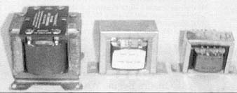
PHOTO 1: A selection of available PA Line transformers.
You can use a high voltage secondary of a tube power transformer— i.e., a 300- 0-300—for a push-pull amplifier. The efficiency will be low due to the primary windings not being made around the center of the core, plus the DC resistance will be different for each leg, resulting in an imbalance in plate load currents and higher distortion. However, for a guitar amplifier, or just fooling around, this may work out just fine.
MICROWAVE OVEN TRANSFORMERS
These are my favorite devices at the moment. Around 3.6 million microwave ovens end up as worldwide landfill each year. While I am not preaching being green here, it is a great opportunity for recycling, something that I have always had a passion for. My wife calls it hoarding.
I always hate to throw out something that may be useful one day (the Amateur Radio credo). My past experience has shown that after cleaning out accumulated junk, the next week I always need whatever I threw out, and then I must buy a replacement. The moral of the story is don’t throw anything out.
The mains transformers from microwave ovens are a great source for the home constructor, because you can easily modify them as both an output and mains transformer for tube projects. Furthermore, they are readily available and usually free from microwave oven repairers or the local re cycling center. My source here in Australia exchanges stubbies (a small 300 milliliter bottle of beer usually sold in slabs of 24) on a one-for-one basis for good microwave oven transformers. A Bud-drinking microwave oven repairer in your local area may also be persuaded into a similar arrangement. (The barter principle here in Australia still does not attract government taxes.)
The transformers come in different forms and ratings. The usual domestic transformer has an intermittent rating of 600 to 700W and is good for 400W continuous. I use them as power transformers for 100W per channel SE amps. The transformers from industrial ovens have an intermittent rating of 1000 to 1500W and are good for around 600W continuous. The cores are welded together, but easy to take apart with an angle grinder. I simply grind off the weld and make a new mounting frame from sheet metal to hold the new transformer together.
PHOTO 2: A homemade output transformer showing bobbin and E & I laminations.
Unlike most transformers that are packed with interleaved laminations, these
are usually packed with the I-laminations one way and the Es the other (Photo
2). This means that you can easily add an air gap for SE use. A single domestic
transformer makes an ideal 100W SE output transformer. The high voltage secondary
becomes the primary for the plate circuit, and you can use the 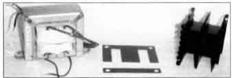 110V primary
as a voice coil output for a 15R load.
Most of these transformers have one turn per volt for the core. This works out to 110 turns for the mains primary and 2400 turns for the high voltage secondary. If you need an SR output, it is easy to modify the 110V primary winding to pick out a tap 30 percent from the outside at around 75 to 80 turns, or simply remove the old primary winding (110V) using a cold chisel and a hammer, and wind a new one. Some of my modified SE output transformers are shown in Photo 3.
For lower output power of up to 65W, you may not need to take the transformer apart to insert an air gap, due to the core size (one of my favorite thoughts on output transformers is why add an air gap when you can add more core). The core material varies depending on the manufacturer, but commercial ones almost always have high-grade GOSS cores, The measured frequency response of the domestic transformers is not fantastic—usually 3dB down at 75kHz, with the low-end usually very good at 10Hz. The commercial high-powered transformers are often good up to 13kHz. The obvious solution (or not) may be to use some feedback around the amplifier to flatten and ex tend the response.
I have used several of these transformers over time, even with the limited frequency response, in amplifiers using an 5E813 for around 50W RMS. The sound has not been disappointing. In one of these, I actually recycled the whole microwave oven, reusing the case, the power supply, and the internal light to show off an 813 inside the oven chamber (even though the 813 produced enough light of its own).
SIMPLE OUTPUT TRANSFORMERS THAT YOU CAN WIND
Over the last 40 years or so, I have seen many methods of constructing output transformers. Some use a myriad of interleaved primaries and secondaries, with nice core material, some wound with litz wire, and so on. These perform extremely well with high efficiency, but have a high price tag (you will get what you pay for). My experience has been that most people who choose to build a tube amplifier love the sound but automatically put older technology and low cost in the same category. The cost of purchasing all new parts to build a tube amplifier is frightening. With this in mind, most of this article shows what you can achieve with little cost and a lot of compromise. One of the best cost savings is to wind your own transformers. For this you need a simple coil-winding machine (described in a future article).
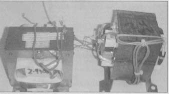
PHOTO 3: Microwave oven transformers modified as SE output transformers.
SIMPLE SCRAMBLE WOUND OUTPUT TRANSFORMER
To wind a simple transformer you need wire, a core, a former, and a plan. The transformer described here is not exactly accurate, but within the ballpark, and does not need a lot of heavy-duty design work to get there. Keep in mind my section about power transformers and others that can be pushed into the job be fore you decide to go down this road. You may wish to keep some of the windings on a power transformer and wind one or more new ones to save on some work. You can also recycle the component parts from the microwave oven transformer here as well, such as the core and mounting frames.
I worked out this simple construction about 40 years ago in my apprentice days. One of the tasks I undertook was to design a 300W push-pull 813 tube PA amplifier for the company I worked for. These were used to provide PA for racecourses, and several dozen were ordered and manufactured. A few variations also found their way to drive multiple quad boxes for local Adelaide rock guitarists. Several of these amplifiers are still in use today, and the owners are most uncooperative to part with them for any amount of cash.
The problem I faced back then was that no two wound transformers tested the same on the bench. This invariably came down to a number of manufacturing and simple assembly errors. An idiot-proof design was needed. Unfortunately, if you have idiots working on a production line, a foolproof design may not be enough (yes, you may quote me on this).
Assuming that you are the brave and adventurous type, this is how to go about it in a few simple steps. Work out the transformer peak-to-peak swing and multiply it by 0.35 for the RMS. As an example, a push-pull 6L6 amplifier running from a 400V DC supply would provide 1600V P-P unless the tube forward voltage drops off approximately 400V, leaving you with 1.2kV P-P. This works out to 420V RMS.
Next, work out the secondary voltage in RMS. For example, for 20W RMS, allow a 20 percent loss in the transformer so the voltage required is for 24W into 8R, approximately 14V. Next you need a core for this power rating, as s a lower f3 of 20Hz. You can pm’- chase a core, bobbin, and hardware from a supplier to suit, or take a stab in the dark with any available core around.
The best-guess method I use is to look at a similar-size power transformer to the core you plan to use, and work out the approximate VA of the power transformer. To do this, you add up all of the secondary winding capabilities. This is an easy step if you are going to strip an existing transformer, because you can work out the VA rating exactly.
Next, for a hi-fi transformer, divide the VA by 2.5 (for a 50Hz) or 3 (for a 60Hz) power transformer core. For my example, the core I was going to use is the same as a 100VA power transformer at 60Hz. Divide by three, and you end up with an audio core good for about 30W. Next you need the turns per volt (TPV). As a guide for 5. to 50VA cores using 10PV, 50 to 100VA use 5TPV, 100 to 250VA 2.5 TPV, and 250 to 500VA 1TPV. This is not exact by any means, but a good rule of thumb.
If you are stripping an existing transformer and the 110V or 240V mains windings are intact and you do not wish to count turns, you can thread ten turns of fine gauge wire through an air space on the existing bobbin, and mea sure the no-load voltage with a digital multimeter. Divide ten by the measured voltage to get the TPV of the core. The TPV is even easier to work out: you can simply count the number of turns as you unwind a winding (preferably a low voltage one, which has fewer turns to count), divide the number of turns by the measured winding, and you end up with the TPV.
Multiply the TPV of the core by the voltage you need in order to get the required primary and secondary turns. Knowing the available window size of your core, look at some wire size charts to pick a gauge of wire that will fill 80 percent of the window.
The primary is wound on the former first, using a split former. In this way, each half of the primary is wound at the same time, and will always have the same number of turns even though the primary/secondary ratios may change a little. The primaries can be scramble-wound without interlayer insulation for simplicity in construction. A layer of insulation between the primary and secondary comes next, followed by winding the secondaries in the same manner.
This gives you a transformer with two split primaries and secondaries. For an SE transformer, the primaries are wired in series. For a push-pull, the common wire comes out as the transformer center tap. You can also wire both secondaries in series. If you have enough window space to wind twice the number of turns, you can also use parallel hookup options. An SE transformer needs to be packed with an air gap; a push-pull does not.
This method does not account for is sues such as calculating the primary inductance and others that you would normally do to make a high-quality out put transformer. This is a quick and simple transformer to make (Photo 3)— less than an hour and with minimum cost, and with very close DC resistances for each half of the windings, better than in many commercial versions.
BIAMPING AND ESL TRANSFORMERS
After spending much time playing with ESLs and multiway systems, I discovered a really low-cost solution for out put transformers.
In ESLs and multiway systems, it is convenient to have multiple amplifiers and panels, each covering a different part of the spectrum, usually no more than four octaves. An alternative to an iron core transformer is the ferrite or pot core. These have usable core use down to 300Hz for some cores. A small 2” diameter core is good for up to the 100W power level; the TPVs are low, and the cost and simplicity worth consideration.
I have used pot core output transformers to drive midrange and tweeter panels with much success. The design guides for their use are well outside of this article, but a good reference is the Philips components and materials handbook for potcores (C4 12-81).
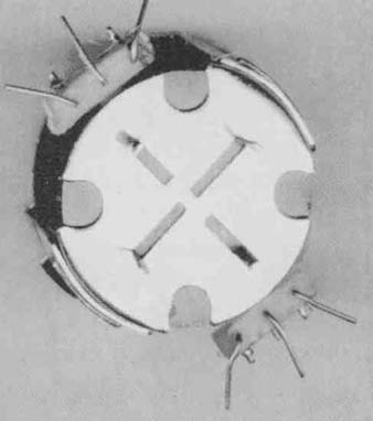
PHOTO 4: 100W pot-core ESL output transformer for a midrange panel.
For ESL panels, a simple output transformer is shown in Photo 4. 1 wound this output transformer using a split bobbin with both windings made at the same time. This one has 300 turns on each part of the bobbin and is wired as a center-tapped choke. The center tap goes to the DC supply and the other ends to the tube anodes and ESL plates. A negative diaphragm bias voltage minus the DC plate voltage is used.
I have also tested line output transformers (LOPT) and switch-mode power-supply transformers (Photo 5). The LOPT tested was from an older black and white set without an integral tripler or rectifier. The frequency response tested was from 1kHz to beyond 200kHz.
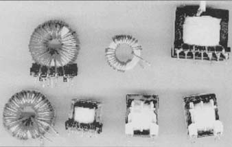
PHOTO 5: Selection of transformers taken from unused computer SMPSU.
The turns ratios and existing windings made these useful for a transmit ting tube such as an 813 or 807. The anode is wired to the old primary and the ESL plates to the HV secondary side. A single 10M-ohm resistor to ground from both secondary wires provides a return path for the diaphragm bias.
On one occasion, I also tried using the EHT rectifier and a 1nF 5kV filter capacitor to provide an audio-driven bias voltage. I used a lightning gas arrestor as a VR tube. It turned out that it was too hard to regulate, so I used a more traditional arrangement.
The SMPSU transformers I tested all had useful output from 75kHz to be yond 200kHz, so were not suitable for audio use, but possibly good for ultra sonic pest eradication.
SETTING THE BIAS IN PUSH-PULL AMPLIFIERS
Without leaving the subject of output transformers, it is worth a few lines to explain my method of setting up the bias for a push-pull amplifier. Thecom promise here is a DC imbalance in the output transformer versus maximum usable plate dissipation of each tube, without a bifilar or split bobbin output transformer. You can never have both at the same time.
Many different ways of setting up the bias current in a push-pull class A amplifier have been published over the years. The most common method is to measure the cathode current and balance it for each tube. The second is to place a DC voltmeter from plate to plate and adjust for minimum voltage. Both of these methods fail for a number of reasons, including assuming that the anode voltage is the same as the supply voltage, failing to deduct the cathode bias and output transformer DC voltage drops to derive a total anode voltage, and assuming that the DC resistances of both halves of the output transformer are the same. My method is not simple but, I believe to be closer to optimum.
First, I pick one tube as the reference tube. I set this one up first, then the other. You need to know the maximum plate dissipation for the tube you are using. This information is available from data sheets or from the web.
Remove the second output tube. Measure the voltage from anode to cathode and the cathode current of the reference tube. The two multiplied together should equal the plate dissipation for a class A amplifier. You can ad just the bias voltage until the sums work out.
Next, install the second tube, and using a low-cost toy compass on top of the output transformer, adjust the second tube bias to ensure the compass does not deflect from north. Turn the chassis 90° and check again. Any imbalance in the output transformer magnetic field will cause the compass needle to deflect. If the core has a zero state of magnetism, then all is well.
The magnetic flux produced in the core of a transformer is dependent on the number of turns and the current that passes through it. Because most output transformers will have dissimilar primary resistances but the same number of turns, the DC voltage drop across them will be different. As such, the primary half with the larger voltage drop will need that tube to draw more current for the same plate dissipation. The offset is that by drawing more cur rent, you may unbalance the output transformer and cause a residual magnetism. I have often found many amplifiers deliver nowhere near the rated output power or end up in class AB2 due to poor setup, or an increase in THD due to the imbalance.
INVERTER TRANSFORMERS
For those interested in car glass audio, the thought of building a DC to DC inverter has often been a problem. There has been little published about inverter transformers, and this is in the Black Art area lam trying to de-mystify.
The best method I found for winding an inverter transformer is to recycle the microwave oven transformer (working out new ways to recycle these is one of my favorite pastimes). I often remove the primary or secondary winding (de pending on the output voltage required) with an old woodworking chisel and hammer. The core has 1TPV for the windings, there are usually 2400 turns on the HV secondary, and either 240 turns or 110 turns (depending on country of origin) on the primary.
For example, if I need around 350V DC at 1000mA, I remove the HV winding and add two windings of eight turns of car booster cable bi-filar wound for the low voltage primary. If I need 1500V at 200mA DC, I remove the 240/110 primary and wind the same two lots of eight turns for the primary and make a tap on the HV secondary winding at around 45%. Remove the core welding and the “I” laminations with an angle grinder, add a piece of 70GSM card as an air gap, and some new mounting frames, and, presto, you have a good 300—400VA inverter transformer. You can use the commercial microwave oven transformers for higher power up to 1kW.
============