|
|
When the first public motion pictures were shown in the early 1900s, the primary concern was that the image be large enough and bright enough for the paying audience to see. Sound in the auditorium was only important in that people needed to be able to hear the organist who improvised theme music to accompany the video. When Warner Bros. introduced talkies in 1926, suddenly the acoustics of the theater became important. Not only did the movie sound need to predominate over projector noise and externally introduced noises, but also the amplifiers and speakers of the day could only provide very small amounts of acoustic power.
By the 1970s, color movies were the rule rather than the exception, Cinemascope had been introduced, and stereo sound was used in most major theaters. But it was the introduction of Dolby and THX that spurred the advent of serious home theaters. Because enthusiasts might consider designing their own home theater systems, a discussion of the design considerations for a commercial THX-approved cinema may be of interest, even though these standards may be overkill in a home theater.
THX is commonly associated with high-quality surround sound, but the THX certification process involves optimizing every aspect of the cinema experience.
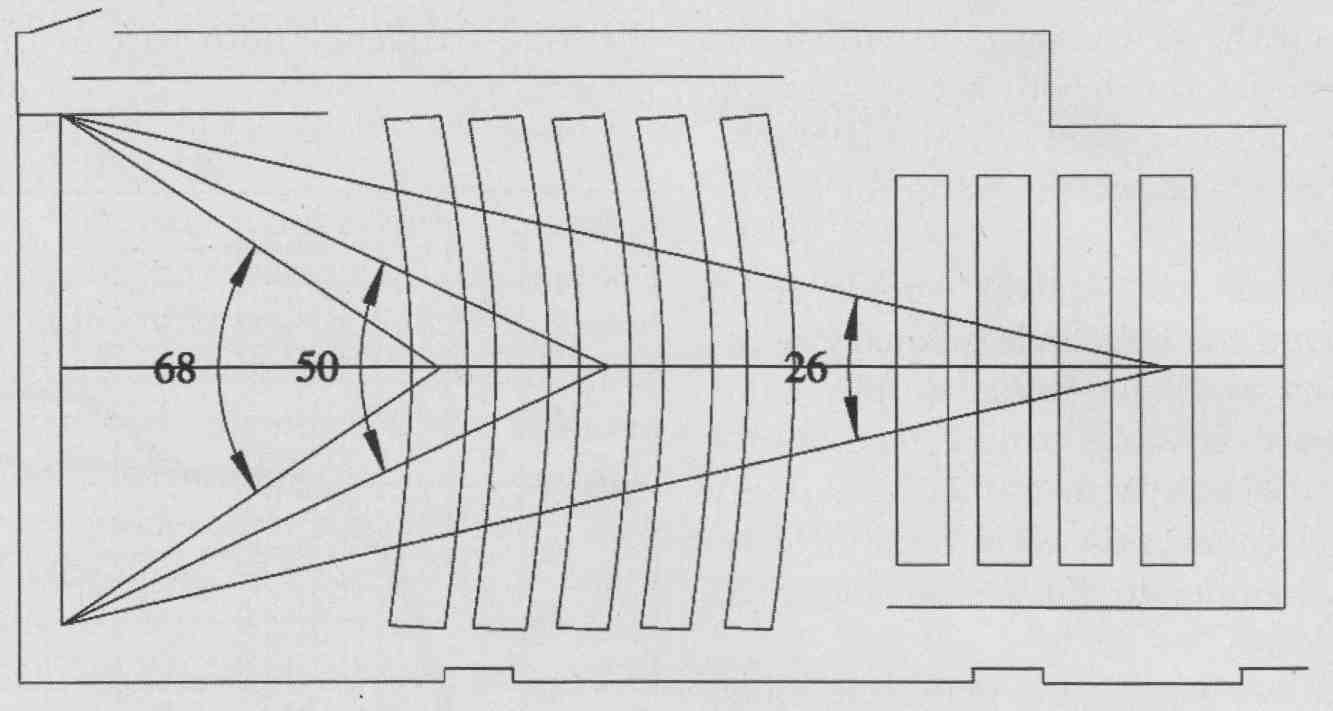
FIGURE 1: Viewing angles.
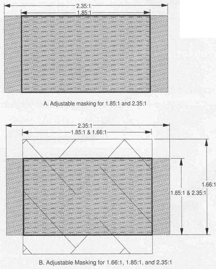
FIGURE 2: Masking for different aspect ratios. A. Adjustable masking for
1.85:1 and 2.35:1; B. Adjustable Masking for 1.66:11 1.85:1, and 2.35:1
LAYOUT
The seating plan in relation to the screen depends upon both visual and acoustical considerations. Anyone who watches movies in a commercial cinema knows that sitting too close to the screen produces business for the chiropractor. however, THX also specifies that the viewing angle defined by the left and right screen edges and the furthest viewing position should not be less than 36” and in no case can be below 260 (Fig. 1). These specifications ensure an optimal visual and auditory experience for the patrons.
TV viewers have become familiar with two aspect ratios: the traditional 4:3 ratio, and the HD ratio of 16:9 (or 1.78:1). Movies, however, are generally produced in the US with aspect ratios of 1.85:1 (standard) or 2.35:1 (Cinemascope). European movies may have a ratio of 1.66:1. Most theaters are designed with adjustable screen masking to accommodate various aspect ratios (Fig. 2).
For optimum stereo effect, you should place the left and right speakers at the edges of the widest aspect ratio projection area. This means that the masking cloth must be acoustically transparent, because it will partially cover the left and right speakers when a movie of narrower aspect ratio is presented.
You can use black muslin or grille cloth as an insert to the masking cloth, or acoustically transparent masking material such as Harkness 2000M. Even with such cloth, you must take care to avoid covering the front of the loudspeaker’s high-frequency section with framing for the masking cloth, or with multiple layers of the cloth. Some commercial theaters have installed fixed screens with 2:1 non-adjustable aspect ratios in order to avoid the cost and bother of adjustable masking. These chop the edges off a Cinemascope movie, and the top and bottom off a standard movie, and therefore good consultants discourage this practice.
In order to keep the sound even front-to-back and side-to- side, the left, center, and right speakers must be placed above listeners’ heads: between one-half and two-thirds the height of the screen. If the front rows are too close to the screen, the front listeners will be severely off-axis, and will experience poor frequency response in the reproduced sound.
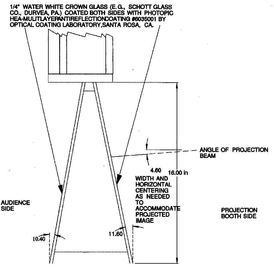
FIGURE 3: Projection port design.
Virtually all professional cinema speakers have a cover age pattern of 90° horizontal by 40° vertical, so the angle produced by the center speaker and the right and left front corner listeners must be less than 90°. Be cause a 90° x 40° horn typically has 6dB less response at the +45° horizontal and +20° vertical angles, especially at higher frequencies, it is a good idea not to expect the main speakers to cover the extremes of their advertised patterns.
VIDEO PLAN
The THX specification must take into ac count film projectors, which have no key stone correction (compensation for projection angle not perpendicular and centered to the screen), so there is a maximum image distortion of 5% specified, with a preferred level under 3%. This image distortion would result from the projector being misaligned with the axis perpendicular to the center of the screen. Digital projectors can correct for this distortion.
In order to isolate projector noise from the theater seating area, the projector is mounted in a separate projection room. The screen is illuminated through a double-glass port. The reason for double glass is to insulate against noise.
If an image is projected through glass at any angle other than completely perpendicular, there will be reflected images on the surfaces of the panes of glass, and these will also be projected to the screen, producing a blurred effect. Therefore, the two panes of the projection port should be angled with respect to the axis of the projected beam. Specifically, the glass on the projector side should be angled out ward from the projector (farther from the projector at the top) by 7°, and the glass on the theater side should be angled 15° backward (closer to the projector at the top) with respect to the axis of the projected beam. Figure 3 illustrates a properly designed projection port.
ACOUSTICS
The first acoustical consideration for a high-quality cinema is noise. This can come from outside the building, from other rooms in the building, or from with in the cinema itself (Heating, Ventilation, and Air Conditioning noise). Nowadays, most commercial cinemas are built in multiplexes, so that the noise from adjacent rooms is that of another cinema. Except for the rare case of a cinema built under the flight path of an airport serving large aircraft, noise sources outside the building are generally less intense than the sound of an adjacent cinema. Therefore, noise analysis can be greatly simplified in designing a multiplex cinema if all adjacencies are assumed to have the noise level and spectrum of a cinema.
For stand-alone cinemas or home theaters, more care must be given to the noise analysis, because the levels of acoustical insulation specified for multiplex cinemas may well be overkill. However, the greater effort spent in analysis and design can easily be rewarded by reduced construction costs if, as is likely, less stringent measures need be taken to keep noise levels acceptable.
The noise level in a room is specified by the so-called “room criterion” (RC). THX specifies a maximum noise level of RC30, with intermittent increases to no more than RC35, and a preferred long-term level of RC25. Figure 4 shows the various levels plotted against sound pressure level (SPL). While not as quiet as a classical concert hail or a recording studio, RC25 is still a low noise level. This freedom from noise is needed for the listeners to hear subtle directional cues and other details in the soundtracks of modern movies.
The noise level in a room depends upon the intensity of the noise source at the outside of the room partition (wall, ceiling, or floor), the acoustical insulation of the partition (specified as “sound trans mission class” or STC), and the acoustical characteristics of the room. In a multiplex cinema the noise source and the room characteristics are known, so it only re mains to specify the STC of the partition walls. THX specifies a minimum STC 75, which is a very stringent specification, requiring massive walls with resiliently mounted surface layers.
Doors, in general, cannot meet this specification: the best acoustical door has an STC of 53, and this requires a fully gasketed, 4” thick door. However, because the total area represented by doors is rather small, they do not add a great deal to noise infiltration. Entrances into the cinema are usually through an acoustically treated hallway, to prevent lobby noise from disturbing listeners when someone enters while a presentation is in progress. Noise isolation is one area where the ser vices of a good acoustical consultant are essential in the design of a quality cinema.
HVAC noise is the purview of the mechanical engineer who designs the HVAC system. There are well-known ways of limiting the intrusion of noise from chillers, furnaces, and air handlers through ducts and vents. These methods are routinely applied in the design of new facilities, although they can be quite challenging to retrofit into existing cinemas.
Any perceptible echo in a cinema must be avoided. Considering the high sound level produced by the speakers, you can see that avoiding echoes requires acoustically absorptive wall and ceiling surfaces. Failure to provide enough absorption on these surfaces results in sound reflections that provide false directional cues, spoiling the realism of the surround sound.
As an example, if the main speakers produce a level of 95dB, and the rear wall of the cinema has a sound absorption co efficient of 99% at 1kHz, the echo produced by sound bouncing off that wall will have a level of 55dB—still quite audible under the proper conditions. The THX guidelines call for 1” of compressed fiber glass on the sidewalls, over a 1” to 2” air space. For the rear wall, the guideline is 2” of compressed fiberglass over a 2” to 4” air space. If acoustical modeling indicates that low-frequency buildup may be a problem, thicker fiberglass and/or thicker air spaces may be required.
The usual ceiling is a 1” compressed fiberglass suspended ceiling, and if noise from rooms above the theater may be problematic, the suspension should be resilient. A 6” thick fiberglass noise batt is installed above the ceiling tiles. Cinema seats must have absorptive bottoms, so that unoccupied seats do not add reflecting surfaces when the seats fold up.
Aside from echoes, which are discrete reflections, sound in rooms is also subject to random reflections called reverberation, which causes an apparent prolongation of the sound events. The time required for a sound at the level of normal conversation to decrease to the threshold of audibility is called the “reverberation time” (RT60) of the room. In a THX cinema, THX specifies the target RT60.
Depending upon the volume of the room (cubic feet), the RT60 can be as low as 0.1-0.2 seconds for a 1000ft room to as much as 1 - 2 seconds for a 1 million ft room. For frequencies below 250Hz, the RT60 is allowed to increase as frequency decreases, to a maximum of twice the mid- frequency value at 31.5Hz. At frequencies above 2kHz, the RT60 can decrease with increasing frequency, to a minimum of one-fourth the mid-frequency value at 16kHz (Fig. 5).
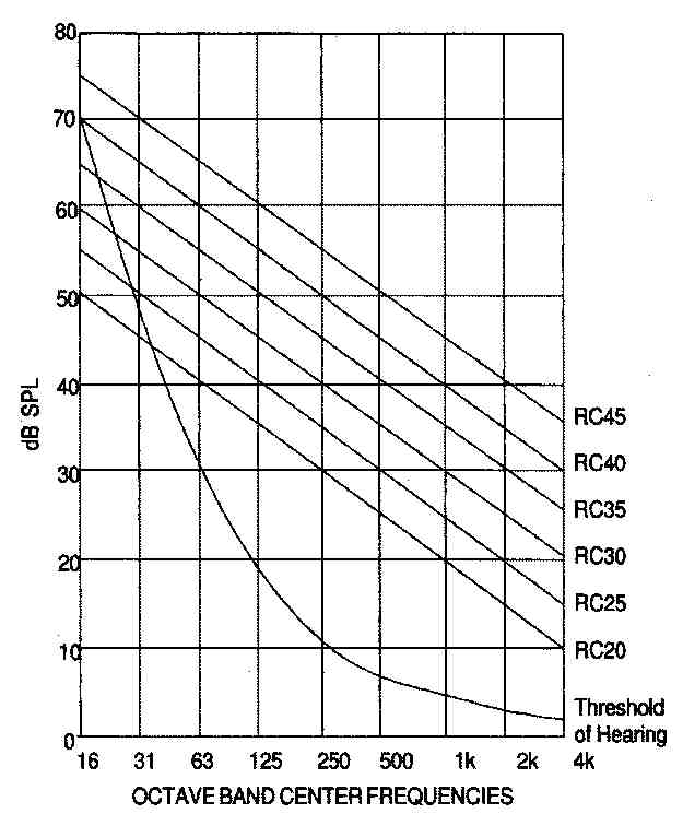
FIGURE 4: Room criterion (RC).
B-CHAIN
The electronics involved in cinema sound reproduction are often grouped into two “chains”: the A-chain retrieves the sound information from the film or other source and splits it into (typically) main left, right, and center; left surround, right surround; and subwoofer channels. The B- chain includes equalization, active speaker crossover units, power amplifiers, and the speakers themselves. A-chain devices are provided by specialized suppliers, while B-chain elements are offered by a few professional sound equipment manufacturers.
The main (L,C,R) speakers are almost always combination designs using vented low-frequency sections and constant-directivity high-frequency horns. Rather than selecting speakers whose coverage pattern places direct sound as precisely as possible on the seating area, as is done for live sound reinforcement, almost all professional cinema speakers have 90° x 40° patterns. And rather than being aimed at the seating area, the main speakers are aimed parallel to the top of the seating area; i.e., over the heads of the audience. In this way, the decrease in response of the horn for off-axis positions compensates for the proximity of front listeners, giving more even front-to-back levels.
Figure 6 shows a simulation of the levels at 1kHz for the same main speakers, aimed at the seating area (top), and aimed parallel to the top of the seating area (below). Note the more uniform sound levels in the latter case. (The level at the back of the cinema is about the same in either case, but the level in front is notice ably hotter when the speakers are aimed at the seating area. The horizontal aim of the L and R speakers is usually about two-thirds of the way back in the room, centered side-to-side, so as to provide the best stereo effect for all listeners.
In order to prevent early reflections that would be detrimental to directional cues, and to provide loading for the main speakers at low frequencies, the L,C,R speakers are normally mounted in a baffle wall. THX has patented a special design for the baffle wall that optimizes its performance across the full frequency range. The baffle wall must be placed very close to the back of the screen, and must be sturdily built to avoid rattles. The L,C,R speakers should be mounted in such a fashion that vibrations will not be transmitted from the speaker cabinets to the baffle wall, or else extraneous wall vibrations will degrade frequency and transient response.
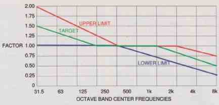
FIGURE 5: Reverberation time for a THX cinema.
The subwoofer (or subwoofers) should be placed in the horizontal center of the screen, under the center speaker. Sturdy, vibration-isolating mounting is even more important for the subwoofer than for the main speakers. Using multiple subwoofers placed at different locations will produce a subwoofer array that will cause hot spots and dead spots in the bass response of the cinema. Only if a qualified consultant specifies spaced subwoofers for particular reasons, after computer-modeling the de sign, should spaced subwoofers be used.
Surround speakers comprise a left- channel and a right-channel group. The speakers are spaced closely enough that listeners cannot localize the sound to a single speaker: they are to act as a continuous source of surround audio. The surround speakers are located above the heads of the listeners, starting about halfway back on the side walls. If the surround speaker arrays extend farther forward than this, their output tends to mesh with the L and R main speakers, confusing the eat
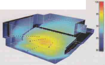
FIGURE 6A: Speakers aimed at audience.
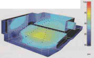
FIGURE 6B: Speakers aimed parallel to top of seating.
Typically, the surround speakers are mounted 10 - 13’ above the floor, and they are aimed at the farthest listener, although the aiming angle can be varied as needed by the consultant in order to provide the most even coverage. Usually the surround speakers are wired in a series-parallel arrangement in order to present a suitable load to the surround power amplifiers.
In a THX design, part of the THX engineering service is to present the owner with a list of THX-approved speakers, amplifiers, and processors from which to choose the cinema equipment. For non THX designs, the consultant should de sign for a maximum SPL of 103dBC (for Dolby® SRD) for each screen channel (L, C, R). This SPL capability (18dB above the reference level) should be available at all frequencies from the 31.5Hz band through the 16kHz band. The reference level is measured at a reference seat two- thirds of the way back in the room, but levels should be consistent within 3dB at all seats. Each surround chain (left and right) should be capable of producing 100dBC at the reference seat.
You must choose speaker wiring to avoid line-heating problems or excessive signal loss, and to provide adequate speaker damping. Fortunately, if the line loss is kept under 0.5dB, the other two requirements will be met automatically. Assume that a subwoofer requires a peak power of 800W, and has an impedance of 8ohm. The sub is located 50’ from the power amplifier. The total resistance of the wiring and speaker is then given by:
R_T = |Zs|/ [1og^-1(-0.5dB/20)] = 8.47ohm
...where R_T is total resistance, and |Z|s is the speaker impedance.
This means that each side of the line must be under 0.235-ohm so the wire must have a resistance of 0.235-ohm per 50’, or 4.7-ohm per 1000’. AWG 17 wire meets this specification. The speaker will draw about 11.2A maximum.
This is below the allowable ampacity (14A) for three AWG 18 wires in a race way; ampacity for AWG17 is not specified, but it would be higher. The damping factor is given by:
DF = |Z| S / R_source + Rs
...where Rs is the DC resistance of the speaker (assume 6 ohm).
Neglecting the very low output impedance of a solid-state amplifier, damping factor is about 1.24. Even with zero resistance in the lines, the damping factor could never be below 1.33, because of the DC resistance of the voice coil Thus designing for a maximum loss of 0.5dB will lead to a very good choice of speaker wire gauge.
TESTING AND ADJUSTMENT
In most modern cinemas, equalization is provided by digital signal processors, with the target response defined by the “X curve” specified in ISO Document 2969 (Fig. 7). You can make adjustments using a single measurement microphone placed off-center in the seating area. However, better results are obtained by using multiple microphones located as shown in Fig. 8.
Mount the test microphone(s) about 9” above the tops of the seat backs. You should use calibrated microphones, and the four microphones can be used one at a time, and then the readings can be manually averaged; or you can feed the mikes to a microphone multiplexer that automatically switches among the mikes. The time averaging function of the real time analyzer then performs averaging among the microphones.
In addition to equalizing the main and surround speakers to the X-curve, the consultant performing the final adjustment must set the sensitivity of the power amplifiers for L, C, R, subwoofer, and surround. When the system is fed pink noise at the reference level (such as from Dolby Cat. #85 pink noise generator), each of the main (L, C, R) speakers should produce a level of 85dBC, and the left and right surround channels as a whole should each produce 82dBC. The subwoofer level is set 10dB hotter, due to the recording standards for subwoofer soundtracks.
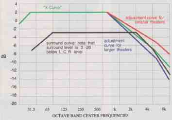
FIGURE 7: X-curve and surround curve.
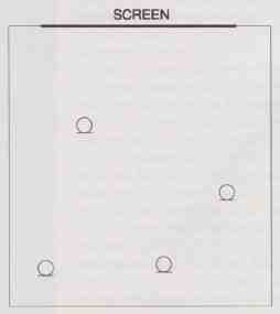
FIGURE 8: Test mike positions.
SUMMING UP
Even though the design is significant and the resulting project may be expensive, cinemas designed to or near THX standards can provide an unforgettable viewing/listening experience.
REFERENCE
1. For an excellent discussion of damping factor, see the indexed references in Audio Cyclopedia, by Howard Tremaine. Howard W. Sams, publ.