|
|
With these modifications and parts replacement, you can bring this sweet-sounding amp to life.
Most DIYers will recognize the Heath W-5M amplifier, which Heath first sold in the 1950s as a high- quality kit for the “audiophile,” a new term for that time. The W-5M was a Williamson-type amplifier built around a very high quality Altec/Peerless output transformer, utilizing KT-66 output tubes.
I have purchased a number of W-5s over the years and am always amazed at how wonderful they sound. With careful up grading and modernizing, they rival any tube amplifier manufactured today. You can perform this rebuild for less than $65 per amp, and with some new tubes it can save you thousands over new equipment—plus you get the enjoyment of doing it yourself.
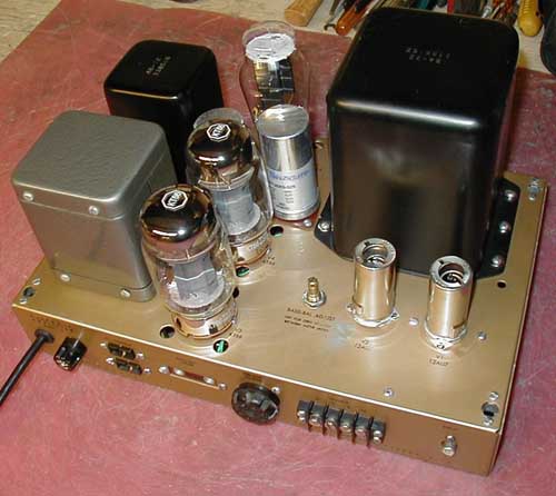
PHOTO 1: The rebuilt Heath W-5M amp.
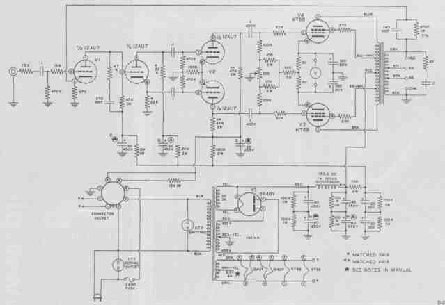
FIGURE 1: Heathkit amp schematic.
CIRCUIT
The basic circuit is easy to follow (Fig. 1). The signal is coupled to one half of I the 12AU7 grid and amplified. It is then directly coupled to the grid of the second half of the first 12AU7, which acts as a split-load phase inverter. The signal at the cathode follows the grid while the plate voltage swings in the opposite direction. The cathode and plates are coupled to the grids of the second 12AU7, and act as a push-pull driver stage through a pair of 0.1uF capacitors. The amplified signals are coupled to the grids of a pair of KT-66/6L6 tubes through a pair of 1pF capacitors.
Feedback is applied from the secondary of the output transformers back to the cathode of the first 12AU7 amplifier stage to reduce distortion and improve frequency response. The output tubes employ a circuit to balance the plate current, reducing harmonic distortion. This “balancing” circuit utilizes a simple voltmeter to perfectly balance the output tubes, which allows the use of unmatched output tubes. The resistor-capacitor string across the output transformer secondary provides high-frequency stability and is referred to as a “tweeter saver.”
FEATURES
Everything about this amplifier (Photo 1) is conservatively designed. The 5R4 rectifier tube is operated well below its current and voltage ratings, and the filter capacitors are “stacked” so that they never approach their maximum ratings. Heath emphasized this in their manuals as a significant advantage compared to equipment of other audio manufacturers.
Since the actual voltage seen by the filter capacitors is around 500V, the use of this stack makes available 900V capacity, which might explain why so many of these amps continue to function 40—50 years after being built. Heath could have used 525V can caps, as Dynaco did in the Mark IIs and IIIs, but in stead chose to be very conservative. I have used a Variac on a number of W5s not used in 20 years, and after a gentle wakening, they have functioned perfectly, with no hum or noise.
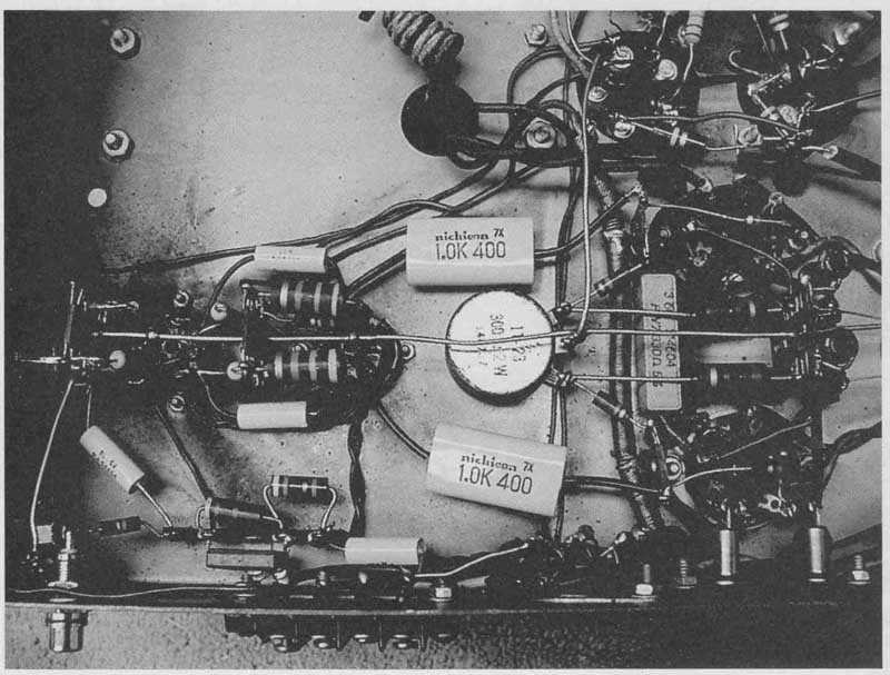
PHOTO 2: Rebuilt amp section.
The W5s used a heavy, potted power transformer, which supplies 140mA of high-voltage current—3A per filament for a tube rectifier and 4A for the other filaments. It also has a 7H potted choke. Even though the total capacitance of the power supply is not huge, these amps are typically hum and noise free. The output transformer is one of two different Altec/Peerless ultralinear potted units. The earliest amps used the larger Peerless 16458, while those sold after 1957 used the Peerless 16309 transformer. In comparison with the power transformer, either one of these outputs seems small. They are, however, very sweet and almost “bulletproof.” There is debate about which is better, but I believe the difference is inconsequential. Either way these amps are very well de signed and conservatively constructed. They are typically rated at 25W output, with an average maximum of 32.4W and a peak of 47.2W. The earlier amps also had a “surge protector” in the AC line, a bimetallic strip heated by an exposed wirewound resistor.
Other significant specs:
• Frequency response of 10Hz—100kHz ±0dB at 0.25W (normal listening level)
• Harmonic distortion typically 0.05% 0.1%
• Intermodulation distortion at <0.1% at 20W
• Hum and noise of 80.2dB below 250mW (normal listening level), 84.2dB below 5W (loud listening level), and 99dB below 25W
• Damping factor 40
The construction manual that came with the kit was well written and illustrated, and allowed even the most inexperienced builder to construct a superb amplifier. In addition, the manual contains many test graphs, charts, and oscilloscope pictures. I highly recommend that before you start to rebuild one of these amps, you obtain a copy of the original construction manual. I have found them available on various online auction services for under $15. I have had good results with WF6G Vintage Manuals (www.w7fg.com) as a supplier of high-quality manuals.
Since many of these amps are 50 years old, it is time to update and re build them to last for another 50 years. I will detail a typical rebuild and update. My discussion will be broken down into two parts: the amplifier section and then the power supply.
Although it is very important to have a copy of the manual, I am including a schematic (Fig. 1) and small pictorial (Fig. 2) for your use. All of the parts you will need are available from Antique Electronic Supply (I have included part numbers). If you use another supplier you must determine the equivalent parts.
AMP UPDATE
I don’t like to drill new holes in the stock chassis, so I designed this rebuild to use existing holes. I will not describe the cosmetic restoration of the amp except to say that to refinish the chassis requires removal of all the components and a complete refinishing and re assembly. (I have not yet found the appropriate color of gold paint to match the chassis’ original finish; if anyone knows, please contact me!)
TABLE 1 -- AMP PARTS LIST
4—0.1uF 630V film caps (Illinois C-TD1-630 or Solon CFSD1-630)
2— 1uF 630V film caps (Illinois C-T1-630 or Solon C-FS1-630)
2 —220uF 160V electrolytics (C-ET220-160)
1— RCA input jack (S-H67R or S-H67B)
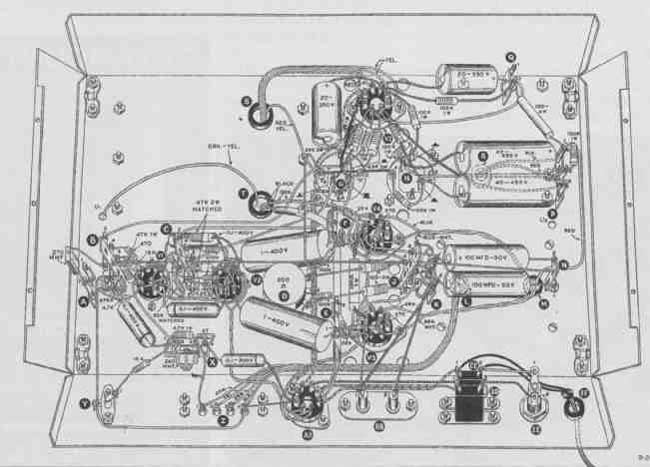
FIGURE 2: Heathkit’s diagram of amp underside.
Table 1 lists the rebuild parts for the amp section. Heath used 400V paper caps, but, again, I decided to be conservative, and use 630V film caps. Whichever you use, you will find that the new ones are less than one half the physical size of the original “pyramids.”
If you are replacing the input jack, carefully remove the ground and bus wire from the input jack, as well as the 15k resistor to the center connector of the jack. Install the new jack and securely attach the ground and bus wires, as well as the 15k resistor.
Next, replace the 0.1 uF input capacitor, then the 0.1uF cap going from terminal X to the front-panel octal socket (AA). If you are not going to use the octal power-supply connection, you can move the ground end of the 0.1RF cap from the socket directly to terminal 4 (Z—output strip). I usually deal with one capacitor at a time to avoid potential mistakes. Next, replace the 0.1 coupling capacitors between tubes V1 and V2.
It is best to clip the leads of the old caps and use a set of hemostats and a pencil iron to remove the excess old leads. Use insulated sleeving on all exposed leads and dress your work according to Fig. 2. (The input sections of the amp are pretty crowded, so take your time and check your work carefully. Extra care here can save nasty sparks later!)
Next, replace the 1uF coupling capacitors that go to the output tube sockets. The last step in this section is to re place the two bias supply electrolytics. Heath used 100uF 50V units; I use 220ltF 160V units, which provide more regulation for the bias supply, and a little more headroom.
Use your digital ohmmeter to check all the resistor values in the amp section. I have found resistors that were over 50% off marked value, even though the amp sounded fine. The most critical are the 47k 2W units attached to the plates of V2 and the 22k units on the cathode and plates of V2. They ideally should be matched to less than 5% difference. I usually replace anything out side 10% of marked value with 5% 1 or 2W metal film resistors.
At this point you have finished the amp section; check everything carefully again before proceeding to the power supply. Your amplifier should look similar to Photo 2.
Table 2 lists the new power-supply parts, which are considerably more compact than the original parts. See the difference in Photo 3.
TABLE 2 -- POWER SUPPLY PARTS LIST
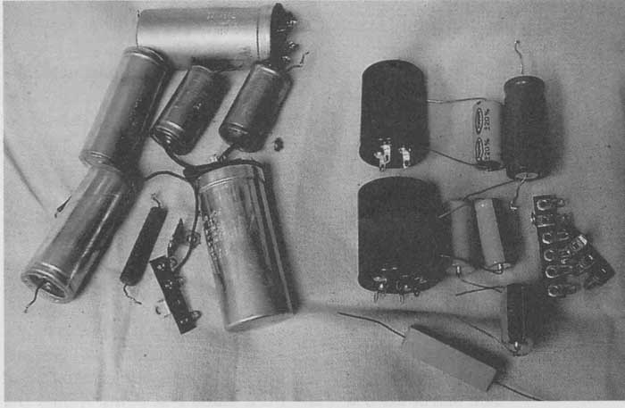
PHOTO 3: Replacements for original components.
POWER-SUPPLY UPDATE
The second part of the rebuild can be confusing, because Heath utilized electronically unused terminals of the rectifier tube as tie points for equalization resistors. Be sure to look closely at the figures and photos. Start by carefully unsoldering all the connections to the original electrolytic cans C and H (or do can G first.) With the exception of two 100k resistors, all the other components will still be attached to some thing else at the opposite end. If you will not be using the front-panel octal socket front power connections (AA), you can remove the 15k 1W resistor attached between can G and pin 5 of the rectifier tube (this is an unused tie point on the 5R4).
You can also remove the wire attached to pin 5 (which was used to power a WAP-2 preamp, which you do not want). Remove the existing mounting screws and the old can capacitors.
The new can caps should be loosely mounted in their chassis clamps, which should be secured to the chassis. It may take a little moving, bending, or filing to get the right fit, depending on the clamps you use.
Once the clamps are in place, turn the chassis over and rotate the caps for orientation similar to the originals. Note the larger can has an extra 40 segment (discussed later), so orient the three 20 sections accordingly. On my cans the 40uF terminal is marked with an X.
Referring to the photos and figures, re-attach all the leads and resistors, soldering very carefully, since many of the terminals have multiple connections. It is critical that you connect the ground bus wire to the negative lead of both can caps. Replace the outboard individual 20 350V cap with a new 22pF cap, and then replace the two large 40uF 450V caps with the new 47uF 450 units (Photo 4).
I usually replace terminal strip Q with a 3-5-lug strip to allow fine-tuning of the power resistor (series or parallel) to obtain the correct voltages. You can actually leave the 100-ohm resistor in place until later, or just leave nothing connected between the Q and P terminal strips. Replace terminal strip P with a 6-lug unit and move the 2-lug unit that was at P to the lower terminal of cap can H. Wire the top portion of the 6-lug strip exactly the same way in which the 3-terminal strip was wired. Now wire the 40uF section of the large can cap to add it to the power supply after the choke (Fig. 3.)
Attach a wire from the 40uF section of can G to terminal 3. At the same time attach one of the new 100k resistors to the 40uF terminal and attach the other end of this resistor to the grounded terminal of the small strip (2 lug). Connect the other new 100k resistor between terminals 1 and 3. Run a wire from terminal 1 of this strip to terminal 4 of the new strip P. Connect the remaining 47uF 450V cap negative terminal to lug 1 of the small strip and the positive end to lug 4 of new strip P.
Connect a wire between terminal 1 and terminal 4 of the new 6-lug strip P. This effectively doubles the filter capacity of the power supply after the choke. As mentioned before, you will need to increase the 100-ohm power resistor (between strips P and Q) to between 300 and 1000-ohm during the final check-out. Your completed amplifier should look similar to Photo 5.
Now, double-check all your wiring of the power supply. You can insert the 5114 tube and slowly power up the sup ply to check the voltages before and after the choke connections on terminal strip Q. You should have around 510V DC before the choke and slightly less after (the exact voltage is not terribly important at this point; you are just checking out completed power-supply wiring.)
Hook up a dummy load and input source to the amp, insert all the tubes, and slowly bring up the line voltage. Referring to the schematic, measure the voltages at the following points:
Plate terminal pin 1 of V1 (12AU7), 88V
Plate terminal pin 6 of V1 (12AU7), 280V
Plate terminal pin 1 of V2 (12AU7), 255V
Plate terminal pin 6 of V2 (12AU7), 255V
If these voltages are more than 20% outside listed values, you will need to increase or decrease the value of the 100-ohm power resistor connected between terminal strips P and Q—anywhere between 300 to 1000-ohm. Use a 10W series or parallel string to get a value that provides the needed voltages. In order to get exact voltages at all these points, you can also change the values of the 15k, 22k, and 6.8k resistors connected to can G and the tie point on the rectifier tube. (If you are obsessive, remember that Heath allowed a 20% variance.)
To balance the output tube voltages, attach a DC meter to the terminal BB of the front panel test point. Adjust the balance potentiometer (D) for a zero voltage reading. You can also use these test points to read the actual cathode bias on the 6L6s by measuring the voltage from each of these points individually to ground. They should read between -40 and -50 v.
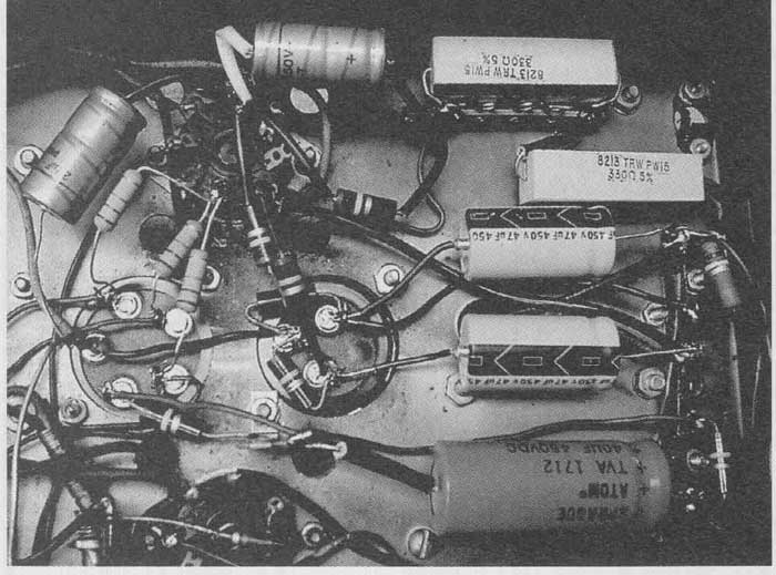
PHOTO 4: Power-supply mods.
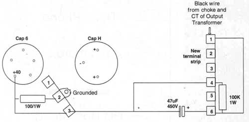
FIGURE 3: Wiring guide for power supply.
Now, measure the plate voltages on the 6L6s (pin 3 of each tube). Heath lists 480V DC as the correct voltage, but yours will probably be in the 500 to 540V range typical of today’s line voltages. (Mine vary from 120—12W AC.)
When these amps were designed, the typical was around 110—117V AC. You can lower this by using an additional 10W power resistor in series with the center tap of the output trans former (moving the red center tap wire from terminal 1 of strip P and attaching it to the unused sixth lug of this strip. Place a 100-ohm 10W power resistor between terminals 1 and 6 of strip F). This may affect your voltages going to the 12AU7s, and you may need to change the value of the power resistor between terminal strips P and 0 to fine-tune everything.
TUBE SELECTION
A word of caution regarding tubes is important at this point: You should not replace the 5R4 rectifier tube with any thing else, unless your actual voltage is low. This tube has the highest voltage drop of all commonly used rectifiers, and to use a 5AR4 or 5U4 will raise your high voltage significantly: 20 to 40V. Luckily, 5R4s are readily available from AES for a reasonable price. If you can get by the appearance of the Chatham “potato masher” style, they are less expensive than the regular versions.
The 12AU7s are common, and even most used ones are very quiet and work well. Many times the original tubes— obtained with the amp—will function very well. The original Heath W-5M used KT-66 Genelex output tubes, which have become very collectible and quite pricey. Many of the amps I have bought still have these tubes in place and they usually test “very good.”
I typically use Sovtek 6L6/5881s, which seem to hold up well. You can also obtain some very nice well-matched, used tubes. I have not found an appreciable difference in sound between these and newer replacements. The suggestion may be heresy, but whatever you like will work. You should not use “coke bottle” 6L6s, since they usually will not take the plate voltages you are likely to experience with this rebuild.
Photo 1 shows a slide switch in place of one of the AC outlets on the front panel. If an outlet is broken, replace it with a DPDT slide switch (AES P-H35- 242), parallel the DP sections, and wire it as a power switch. This switch fits the holes in the chassis perfectly, so it re quires no chassis modification. You can either wire the switch and the outlet to use the outlet as a preamp on/off, or leave it on as a constant, whichever works for you.
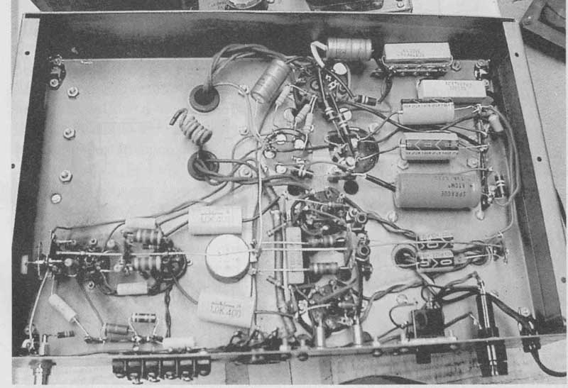 PHOTO 5: Completed mods.
Once everything is in order, you can hook up your amp to some vintage speakers and enjoy the sweet, mellow sound these amps produce. Occasionally check the balance voltage at the front panel connection. If this requires frequent adjustment, you’ll need to re place the malfunctioning output tube or tubes. If you did not replace the 1uF units in the amp section during the rebuild, this can also indicate that the caps are leaky and need to be replaced. Since many of these amps have functioned for 40 plus years, with this rebuild you can expect many years of trouble-free service.
============