Let’s clear up some misconceptions regarding grounding and audio gear.
The annual conventions of the Audio Engineering Society are packed with technical papers, tutorials, seminars, and exhibits. Press coverage of the convention has become increasingly difficult due to the sheer size of the event. This year, rather than attempting an overview of the convention’s proceedings, I decided to highlight one session that stood out as being particularly outstanding. On October 7, 2005, at the Jacob Javits Convention Center in New York City, Bill Whitlock, President of Jensen Transformers, Inc., gave a three-hour tutorial seminar titled Audio System Grounding and Shielding: An Overview. (Whitlock became President of Jensen following the untimely death of company founder Deane Jensen in 1989.)
Whitlock sought to dispel many of the myths surrounding grounding and system interfacing, noting that the subject abounds in black art and myths. Basic rules of physics are routinely ignored, and even many manufacturers “don’t know ground loops from Froot Loops” (the last comment was typical of the touches of humor that Whitlock brought to his presentation, though there was serious intent behind each of them). If a system contains two or more pieces of grounded equipment, a ground loop may be formed if the chassis of the connected equipment are at different potentials. This will typically happen if the various pieces of equipment are powered by different AC branch circuits.
The most common approach to solving hum problems due to ground loops is by lifting safety grounds with “ground lifters” sold in any hardware store. Whitlock warned against this approach, noting that safety grounding keeps AC line voltages between equipment safe even if equipment fails. His view is that you should never use ground lifters even if a manufacturer’s instructions tell you that it’s OK to do so.
Whitlock noted that the ground adapters sold in hardware stores, while superficially appearing as ground lifters, are actually intended to provide a safety ground when grounded (3-pin) power cords are used with 2-prong receptacles. They are designed to add a ground, not remove one, by putting the outlet plate screw through the ground tab on the adapter! If un grounded equipment suffers an internal failure of insulation or components at the AC line input, the equipment chassis can turn live with 120V AC if the safety ground is not connected (Fig. 1).
Whitlock also recommends GFCI (Ground Fault Circuit Interrupter) outlets for safety. These outlets sense differences between line current and neutral current (fault currents). Any difference between line and neutral current may be current flowing through a human, which can be a deadly problem. GFCI outlets trip at 4 to 7mA of current, protecting the individual in contact with the “live” equipment.
He also dispelled some of the myths surrounding earth grounds, noting that earth grounds are for lightning protection. The safety ground in a modern electrical system is tied to neutral at the entrance panel, and earth ground plays no role in protecting people from electrocution. Earth grounds are invariably not at 0V, and two earth grounds will rarely be at the same potential. Earth ground rods are useless for protection against fault currents, and are equally useless for reducing noise.
HUM CAUSES
Myths abound regarding the causes of hum in audio systems, and hum is rarely caused by bad audio cable shielding or AC distribution. You can trace the vast majority of hum problems to faulty system interfacing. Pro sound engineers routinely engage in dangerous practices in the field--adding ground lifters to AC power cords--in order to quickly eliminate hum problems. Defeating safety grounds is dangerous and illegal, and makes the person who did it legally liable. Whitlock emphasized that such practices have resulted in people being killed and companies forced out of business because of lawsuits.
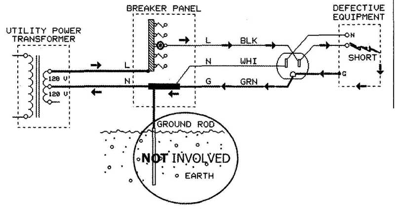
FIGURE 1: Internal equipment failure can render a chassis live with 120V AC.
The safety ground ensures that the chassis remains at 0V potential, tripping
the breaker in the panel for that branch circuit, and protecting the user from
potentially lethal voltages. Earth ground Is for lightning protection, and
plays no role in fault protection.
The only safe way to solve hum problems is through proper system interfacing. Whitlock provided a great deal of useful background on the causes of hum in un balanced interfaces, and gave an excellent overview of the requirements for balanced interfaces.
Balanced lines are not balanced because they carry audio signals of equal level but opposite polarity (though they normally do). They are balanced because of careful impedance matching of the two signal carriers with respect to ground, especially the source (driving) impedances. If the impedances of balanced lines are not care fully matched, by definition they are not truly balanced. Common-mode rejection will be compromised, which reduces the system’s ability to reject noise coupled to the signal carriers.
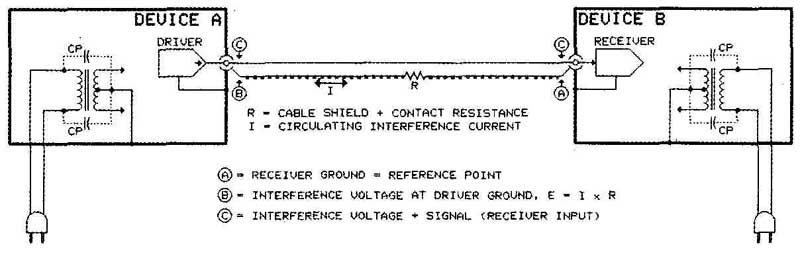
FIGURE 2: When two grounded chassis are at different AC potentials, circulating
interference current will be carried by the interconnecting shield. Noise voltage
will be generated over the length of the shield due to the shield’s resistance.
This noise voltage is added to the signal arriving at the receiver due to common-impedance
coupling.
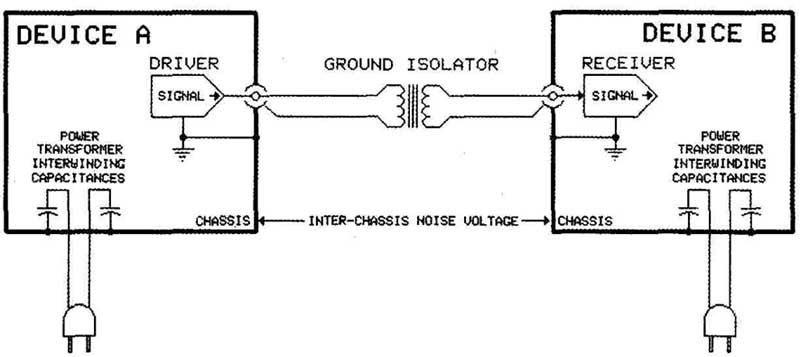
FIGURE 3: Ground isolators eliminate the electrical connection between the
driver and the receiver. No noise current flows in the cable shielding. With
properly designed Faraday-shielded Input transformers, noise coupling is effectively
eliminated.
In unbalanced interfaces, leakage currents flowing in signal cables are the root cause of most hum problems (Fig. 2). Leakage currents are normally carried by the grounded conductor -- the shield -- which does not have a zero ohm impedance. Ohm’s law tells us that the resistance of the shield generates noise voltage over the length of the cable. This noise, in turn, is added to the signal at the receiver.
The correct way to eliminate hum problems in audio interfacing is with transformer isolation (Fig. 3). Trans formers transfer the signal voltage from the primary to the secondary windings without any electrical connection between them. So, there are no noise currents flowing between the connected devices. With a properly designed transformer, hum is eliminated while safety grounds remain intact.
Reducing ground noise in a transformer-coupled interface depends on the type of transformer used. Output transformers typically have closely spaced primary and secondary windings. This increases the capacitance between the windings allowing efficient high-frequency noise coupling between the windings, which is undesirable. Input transformers typically employ a Faraday shield between the windings, which virtually eliminates capacitive coupling. This, in turn, greatly improves noise rejection of a transformer-coupled interface, including RF and ultrasonic interference.
Many transformer-based “black boxes” sold to eliminate noise caused by ground loop problems employ output transformers. Their low output Z allows these devices to be placed anywhere in the signal path, because their outputs are not sensitive to the capacitive loading caused by long cable runs. Input transformers, on the other hand, offer a 30dB improvement in noise rejection over output types. But, their relatively high output Z requires that they be placed within 2 or 3’ of the receiver in order to prevent degradation of their high-frequency response by the output cabling.
Whitlock noted that normally an unbalanced interface using a single isolation transformer close to the load will solve the noise problem. Only in unusual circumstances is a balanced interface necessary. Converting the entire interface to balanced is necessarily more complicated because it requires an unbalanced to balanced conversion at the source, and a balanced to unbalanced conversion at the load. In other words, two transformers rather than one.
One pet peeve of mine is the notion that professional audio systems should be designed to operate at matched impedances of 600-ohm. Naturally, I was de lighted when Whitlock dispelled this nonsense. He correctly noted that 600-ohm impedances are holdovers from early telephone practice, but are not applicable to modern audio systems that are driven by signal voltage.
Modern audio circuitry is designed with low output impedances and high input impedances. This way, audio circuits are not subject to unnecessarily low Z loads. He also correctly noted that signal level, impedance, and line balance are three independent parameters. Impedance has nothing to do with level, and only its matching in the two signal conductors has anything to do with whether the line is balanced or unbalanced.
= = = =