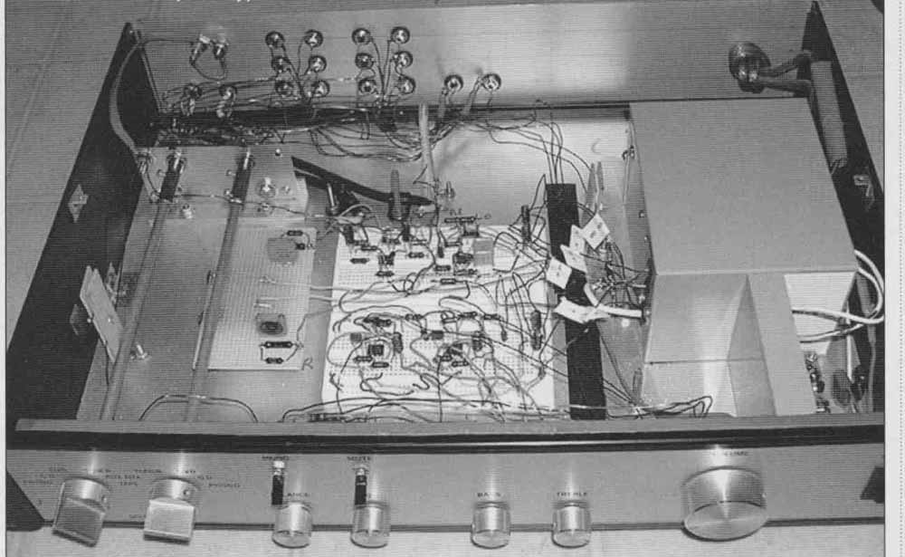
The design for this phono preamp is simple, includes inexpensive parts, and features the use of inductor over capacitor.
Despite the mass attraction of cheap (and typically highly compressed) downloads in the digital age, the LP still lingers in some circles as a desirable musical alternative (or antique collectible). Often times the implementation of a phono preamp for playback is either looked at as an afterthought, or given the status of a black art of the past, with subtle intricacies not readily appreciated nowadays.
BACKGROUND
In order to understand the job of a phono preamp, a brief overview of the various components in the system is in order. Stating the obvious is the LP itself. Typically made of vinyl and usually mastered to the RIAA standard, the amplitude information stored in its groove is not flat with frequency, but rather follows the curve of Fig. 1. Extracting the information from the groove has typically been the job of a cartridge/stylus device (though lasers have been used in some instances). There have been different types of play back cartridges developed, but the most popular by far has been the magnetic type.
Consisting of small magnets and coils, the magnetic cartridge is essentially a small generator whose output exhibits a rising amplitude with increasing frequency for a fixed record groove amplitude (Fig. 2). Superimposing the two curves of Figs. 1 and 2 yields the curve of Fig. 3, the inverse of what the phono preamp must do to produce a flat system frequency response.
Traditionally the RIAA playback curve (Fig. 4) has been implemented with an RC network, either in the feed back loop of an amplifier, or using a “passive” approach; i.e., an RC attenuator to ground between two amplifier stages. The feedback configuration has the advantage of needing only one amplifier per channel (helpful with complex discrete designs), but places a high open-loop gain requirement on the amplifier itself The passive design splits the gain requirement between two amplifier stages, making it easier to achieve high performance with modest amplifiers.
CIRCUITS
A third topology also exists, a variation of which is presented in Fig. 5. Essentially a hybrid of the two approaches, one part of the curve is corrected for in the first stage, while the other part is corrected for in the second stage. Refer ring to Fig. 5, the first stage of the pre amp corrects for the slope of the magnetic phono cartridge (Fig. 2) via the use of an inductor, L1, and also produces the 50Hz breakpoint in Fig. 4.
The use of the inductor to compensate for the cartridge slope seems to be pivotal for sound improvement, because no capacitor implementation sounded comparable (the reason for this re mains speculative). The type of inductor doesn’t seem too critical, as long as it has sufficient ambient noise rejection, and doesn’t saturate in the audio band. I used a small 2 toroidal inductor (originally manufactured by Dale) in the prototype. Others have wound their own on shielded pot cores and actually achieved better electrical performance than with the toroids (see source recommendations).
The second stage of the circuit corrects for the record groove characteristic in the midband areas at 500 and 2122Hz (Fig. 1). It’s interesting to note that you could plug a ceramic phono cartridge into this second stage with nothing more than the addition of a 1.5M bias resistor to ground and the removal of C13.
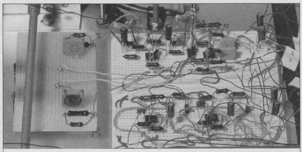
The ±9V power supply is provided by pi filters. No regulator is used, as sufficient headroom to the op amp’s maximum operating voltages exists with the 9V rails, and the pi filter is “stiff” enough not to exhibit much load sag by the drain of the small op amps. The circuit itself is built on prototyping boards. With most unity gain stable op amps, the proto boards have proven reliable. As long as reasonable layout is implemented, there’s no reason to expect any trouble using other construction techniques. Output offset in the prototype ran around 2.7mV with the NJM4559 opamps. If this is unacceptable, you can implement output coupling capacitors.
There are many different types of op amps that will work in the design. I tried over a dozen different types before settling on the somewhat obscure 4559s. For whatever reason, in the application they compared well tonally to discrete designs (they’re also very inexpensive). Obviously you could upgrade to any op amp of choice as long as the operating voltages and unity gain stability criteria are met. The input stage is fairly conventional, with C2 and R2 forming a high-pass filter to help reduce record rumble.
If you desire, you can replace C2 with a jumper for a slightly more transparent sound. C1 is basically a place holder for the desired value of C loading for the cartridge of choice, and should be selected on an individual basis, because turntable wiring, as well as cartridge selection, will influence its value. The resistances of R5, R6, and the DCR of L1 add up to 8-ohm and, combined with the inductance of L1, produce the 50Hz breakpoint shown in Fig. 4. When using various inductors or winding your own for the application, DCR will inevitably vary, so you may need to adjust the values of R5 and R6 to maintain an overall DC resistance of 8-ohm in the circuit leg.
COMPONENT SELECTION
In my experience, you don’t necessarily need expensive parts for most audio applications (and I’ve tried many of them over 35 years). The fact that some people hear a difference doesn’t automatically equate to the more expensive part being the better one. The \ RN6O metal film resistors offer good performance at a reasonable price. Pot cores for constructing L1 are available for a few dollars on the Internet. The 4559 op amps are available for around 50 cents each. The SMG electrolytics made by Nippon Chemicon are quite inexpensive and have some of the best sound I’ve heard for an electrolytic—no graininess, fairly neutral tonality, and natural dynamics.
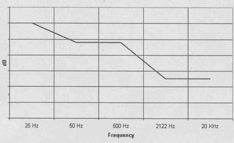
FIGURE 1: Groove amplitude versus frequency for an RIAA mastered Lp.
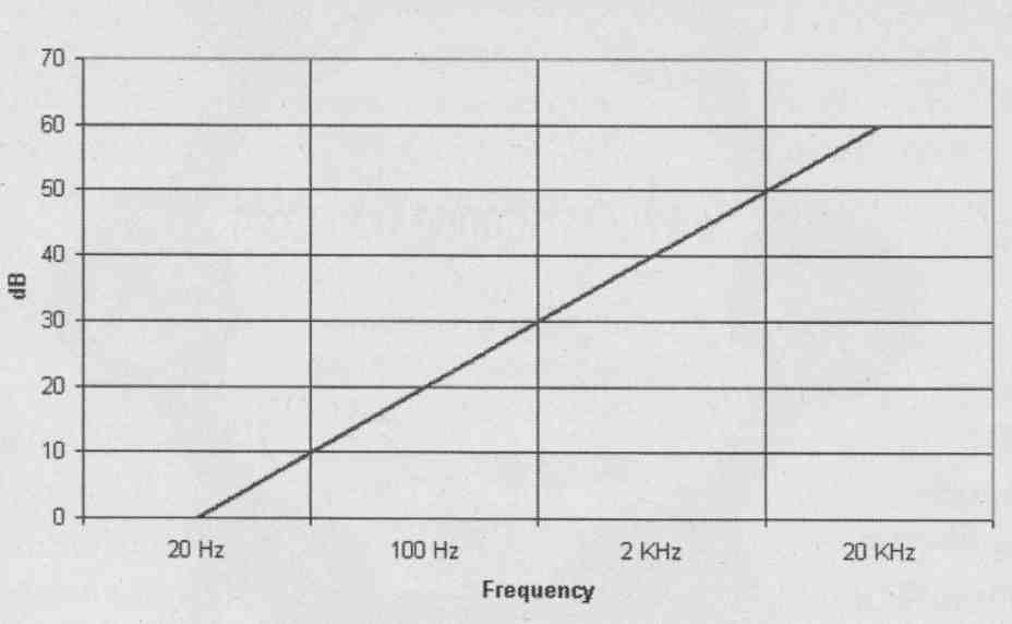
FIGURE 2: Magnetic cartridge response to a constant groove amplitude.
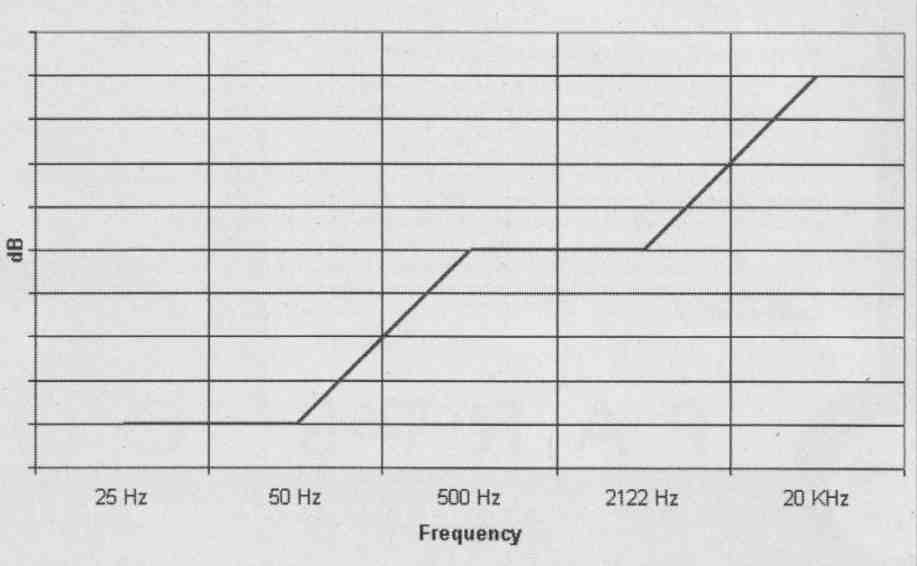
FIGURE 3: Magnetic cartridge output signal for an RIAA mastered Lp.
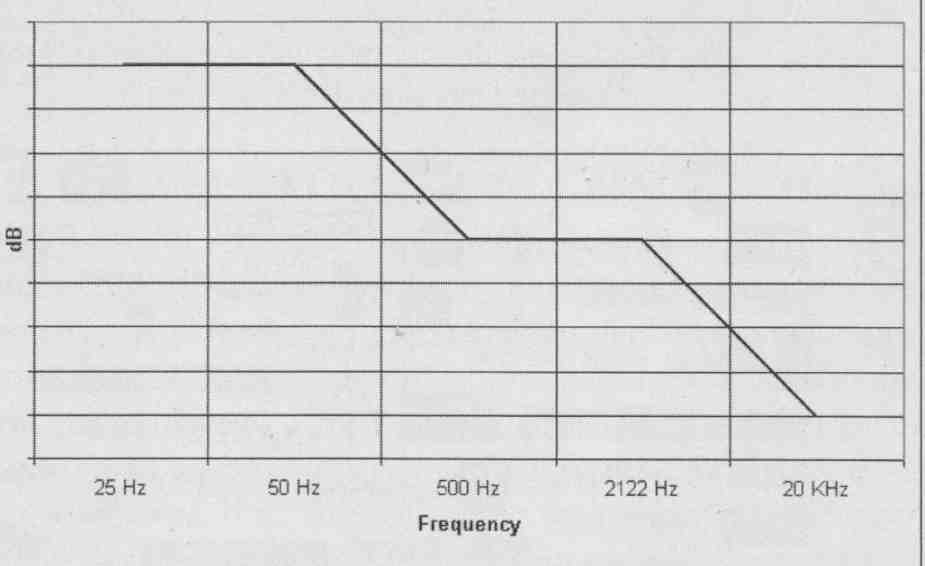
FIGURE 4: Preamp response for a magnetic cartridge.
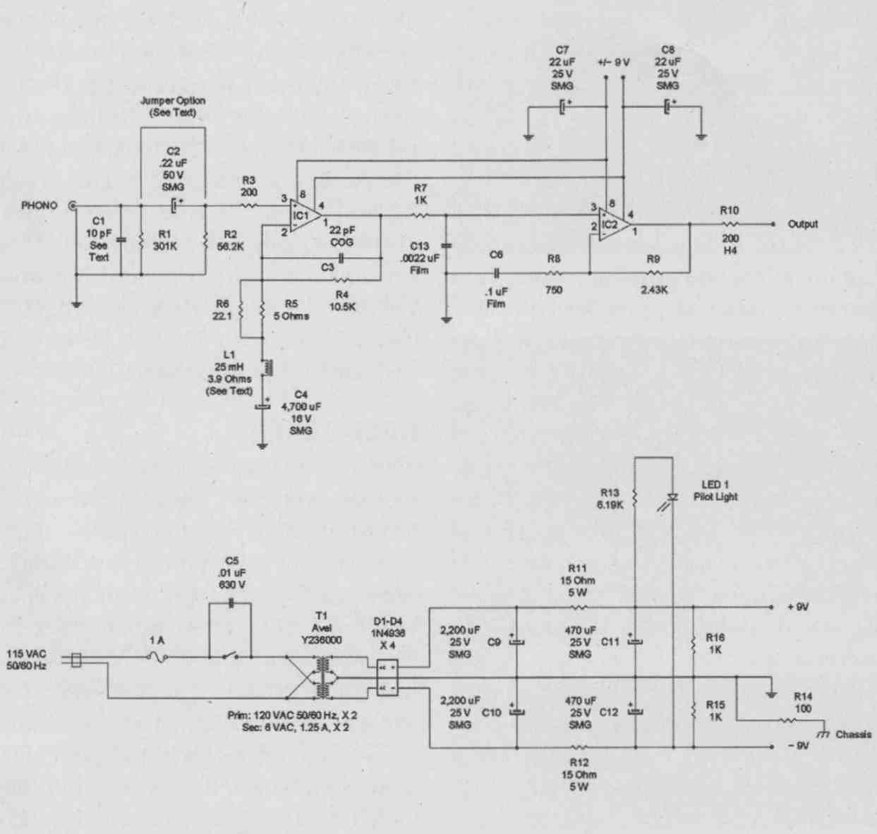
FIGURE 5: Schematic, basic preamp.
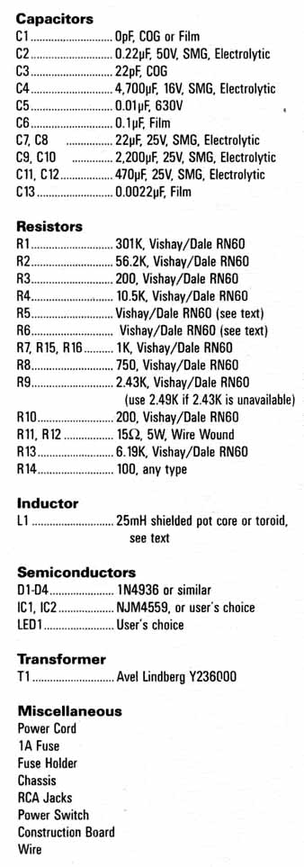
above: PARTS LIST
This isn’t to say that you shouldn’t experiment—quite to the contrary, it’s a great way to learn—but building the preamp with the recommended parts as a baseline is an inexpensive and prudent idea before experimenting. The power supply is adequate to power two channels, but the parts list of the preamp itself will need to be duplicated for the second channel (except for the dual op amps).
RESOURCES
Amidon for the L1 inductor cores: www.amidoncorp.com
Digi-key --diodes, op amps, and capacitors, including the Nippon Chemicon (United Chemicon) SMG electrolytics: www.digikey.com
Mouser -- diodes, op amps, capacitors, and resistors, including the Vishay/Dale RN60s:
Avel Lindberg -- toroidal transformers: www.avellindberg.com
NJM4559 Datasheet (listed under “low noise” op amp): www.njr.com
= = = =
also see: