With little practical information in print, it was necessary to derive this simple solution to the problem of triode cathode-bypassing.
When designing a simple cathode-biased triode, voltage-gain stage of the type shown in Fig. 1, the designer is usually faced with choosing a cathode bypass capacitor in order to maximize gain. If the cathode resistor is left unbypassed, negative current feedback will limit the available gain of the stage to some minimum value. Usually this is a simple matter of using an arbitrarily large value of capacitance to ensure proper cathode decoupling well below audible frequencies.
Occasionally though, some of you may wish to use a small value of capacitance in order to obtain a treble boost E action, because the cathode will be fully bypassed at high frequencies and effectively unbypassed at low frequencies.
This might be called "partial bypassing," and results in the stage operating as a first-order shelving filter. Possible applications include phono stages or pre amplifiers for musical instruments and microphones, where a bass cut is often desirable.
Calculating the maximum possible (fully bypassed) gain is easy, and is given by:
Am = R+ ra (1)
Likewise, the minimum possible (un bypassed) gain is just as easily found using:
A = k.Ra (2) m
Ra+n+Rk(
where, in both cases:
I = the amplification factor of the valve.
Ra = the anode load resistor.
ra = the internal anode resistance (plate resistance).
RJc = the cathode bias resistor.
(If the stage is heavily loaded by a following stage, you should substitute Ra for RaIl Rl, where Rl is the following loading resistance, which is usually the grid leak resistor.)
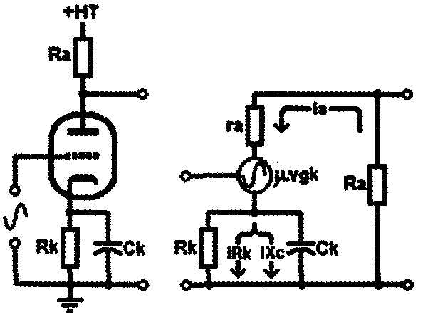
Above: Fig. 1: Left, a simple triode amplifier stage and its Thévenin equivalent
circuit right.
LOOKING FOR ANSWERS
But at what point is the transition made from one extreme to the other? And how should you choose the cathode by pass capacitor to give the desired result? We consulted numerous sources, but none gave satisfactory answers to these questions. The older texts all assume that an audible bass-cut would be un desirable and give this subject almost no treatment at all, while some contemporary texts give incorrect treatment The Radiotron Designer's Hand book (4th ed.) does give a formula for gain at any frequency, on page 484:
… where, all symbols as above, and:
A' = gain at the frequency of interest = 2 pi f
But this is hardly a convenient formula, and even if you solved it for Ck, you must pick an arbitrary level of gain “from the air,” and work from there. Of course, SPICE simulation could solve this problem without trouble, but that could be just as time consuming as solving the above formula. Therefore, we thought it would be more useful to have a universal and simple equation that would allow quick “back of an envelope” choice of the cathode bypass capacitor, or quick analysis of an existing circuit.
A SIMPLE SOLUTION
Normally, filters are defined according to their ±3dB pole/zero frequency. however, this convention is less useful for this type of shelving filter because the difference between A_max and A_min may be much less than 6dB, in which case the pole would be lower in frequency than the zero! In fact, if the difference between A_max and A_min is less than 3dB, then there will be no conventional pole/ zero at all! Instead, the best way to de fine such a filter, which is applicable to all circumstances, is by the point at which gain is halfway between minimum and maximum, which hereafter we call the “half boost point”.
The problem of defining this point is most easily solved using a Nyquist plot of the denominator of equation 2 ( Fig. 2), first by thawing a vector equal to the instantaneous current through Ra and ra, and in series with this, current through Rk(ji + 1). At zero frequency, no current flows in Ck, and anode current (ia) is equal to and in phase with current through Rk (iRk). At maximum gain, Ck is effectively a short circuit, and current through it (iXc) is also in phase with ia. At intermediate gain levels, ia is the vector sum of iRk and iXc, the vectors of which describe a semicircular arc, as shown.
At the half boost point, you can determine the total phase shift (0) in ia by drawing an arc of radius Ra + ra + ½Rk(ji + 1) as shown. Where this vec tor is tangential with the arc ½Rk( + 1), then AB and BC indicate the relative magnitudes of iRk and iXc, respectively, while a/b yields the product of RkCk in radians per second, so that:
a/b = w RkCk
It’s then a simple matter of finding a/b, by treating the problem as two geometrical problems as in Fig. 3, and solving them simultaneously:
To aid algebraic manipulation, put (Ra + ra) = A and 1hPJ(( + 1) = B.
From elementary geometry:
a^2=b(2B-b) (I)
…and,
a = (B-b)(2A + B + b) (II)
Equating I and II,
2Bb=2AB-B^2-2Ab
…and collecting terms in b,
b= B(2A+B)/ 2(A+B) (III)
Substituting III into I and simplifying, …
Putting V over IV and simplifying yields …
… the limits of which are 1 and Finally, putting A = Ra + ra, and B = ½Rk(R + 1) and a/b = w RkCk,
…and solving for f (half boost) (VIII)
Where all resistances are in Ohms, and all capacitances in Farads.
Figure 4 shows the idealized frequency response of the circuit given in Fig. 1 using an ECC83 (12AX7), constructed by drawing a first-order (6dB/octave) slope through the half boost point, found with the above equation and converting to decibels. The heavy line shows the response produced by SPICE simulation, showing excellent correlation. In fact, the accuracy of equations 1, 2, and VIII is limited only by the accuracy of the value used for ra, but this will usually be swamped by the tolerance of the capacitor and triode used. We hope you find this a useful and practical formula to accompany equations 1 and 2 given at the very be ginning of this article, when designing triode amplifiers.
REFERENCES:
1. Admiralty Hand guide of Wireless Telegraphy, 1938. Wireless Telegraphy Theory, vol. 2, section F4. H.M. Stationery Office, London.
2. Langford-Smith, F.(ed.), 1953. Radiotron Designer’s Hand guide (4th ed.), p. 485. Wireless Press, Sydney.
3. Jones, M. 2003. Valve Amplifiers (2nd ed.), p. 79. Newnes, Oxford.
4. Langford-Smith, F.(ed.), 1953. Radiotron Designer’s Hand guide (4th ed.), p 642. Wireless Press, Sydney.
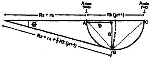
Above: Fig. 2: A Nyquist plot of the denominator of equation 2, a/b yields
the product of Rk.Ck in radians per second.
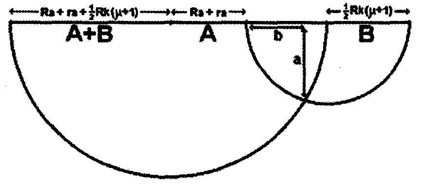
Above: Fig. 3: Substituting the problem in Fig. 2 for a simple geo metrical
problem.
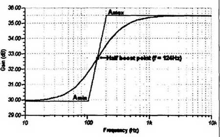
Above: Fig. 4: Frequency response of a SPICE simulation of an ECC83 (12AX7)
in the circuit given in Fig. 1, where Ra = 100kOhm, Rk = 1.5k, Ck = 1uF. A_max,
A_min, and the half boost point were calculated by hand using equations 1,
2, and VIII, with ra = 66kL2.