The fifth in this series of articles on cleaning up AC power lines.
In the first four parts of this series, I explored ways to provide superior AC power for audio systems. Here I look at expanding the system to provide 2400W of clean power. You do this by combining the balanced isolation transformer and oscillator-amplifier combination ( Fig. 1).
The trick is that you need a clean reference oscillator tied to the AC line. You could use the previous transversal oscillator and phase-lock the 555 timer circuit. You would still need a lockout for when it’s not in sync. This approach is quite doable. I, of course, chose a different, older, approach.
OSCILLATOR CIRCUIT
The almost forgotten circuit I prefer is the synchronous oscillator. This is a devious leftover. In any oscillator there is an amp with a frequency-selective level-dependent feedback. When the feed-forward and feedback have 360° of phase shift, it oscillates if the gain is greater than the loss of the feedback network. The oscillation will continue to grow in amplitude until the amplifier clips, which is a very high distortion oscillator. That is why a monitor circuit is used to reduce the gain until the gain exactly matches the feedback loss. This is, of course, impossible to do perfectly, so all oscillators must have some minute residue of distortion.
In the synchronous oscillator I cheat! The gain is just slightly less than the loss through the feedback network. I then inject some of the desired signal into the feed-forward feedback path. This starts the ball rolling and keeps it going. If you limit the input voltage, you achieve a stable, cleaner synchronized output. You can now use a crude limiter on the input signal to keep it stable. A simple circuit, with few adjustments, gives good results.
In Fig. 2, J1 gets 24V AC from a center-tapped transformer. I tapped this off the existing amplifier transformer. The four diodes rectify this and provide ±17V (usually higher due to the light load on the transformer) to the 220 filter capacitors. The regulator chips turn this into ±12V. The output capacitors are small enough so that when you turn off the AC input the regulators won’t be reverse-biased. The current draw of the circuit is only a few milliamps, so no heatsink is required for the regulators.
J2 is designed to accept the reference signal. This can be from extra turns of wire looped around the transformer’s core, the 24V transformer through an additional 47K resistor, or anywhere else you can get a sample of the AC line. The input voltage here should be a volt or two. For my version the reference input is a few turns wound around one of the amp’s power transformers. It gives a good phase match to the output windings.
ADJUSTMENTS
R1 is the input level adjustment. You should set this so that the output is into clipping. The resistors R2 and R3 set the gain of the amp at 11. Diode D5 with the diode bridge provides complete feedback if the output exceeds 6.2V. Two resistors bias D5 to keep it always on, resulting in cleaner clipping action. This first half of U3 is a classic voltage limiter amp.
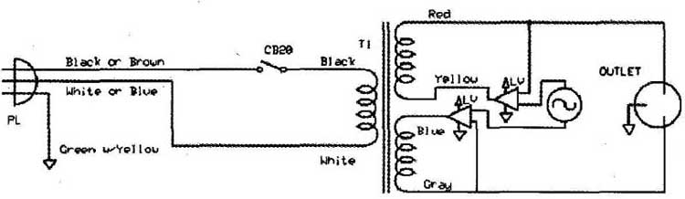
Above: Fig. 1: Center-tapped transformer circuit.
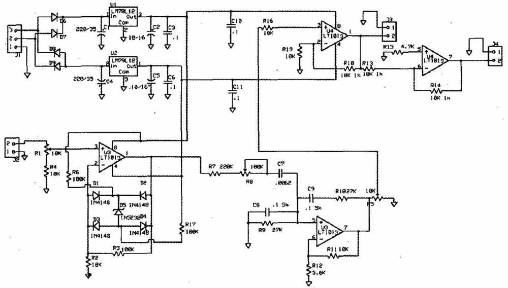
Above: Fig. 2: Oscillator circuit.
If you use an oscilloscope or equivalent, adjust R1 to get a flat top but not a square wave. If you have just a voltmeter, adjust R1 until the voltage slows, rising as you turn the adjustment pot, then give it a bit more. I ended up setting it for the lowest consistent voltage, because that gave me the best final output regulation.
The output at pin 1 U3 still will change a bit with large swings in the AC synchronizing input voltage, but it seems to be fine for my use. This voltage feeds the other half of U3 through another adjustment, R8. This second half of U3 is a classic ‘Wien bridge oscillator, except the gain of R11 and R12 is set too low for it to oscillate by itself.
R8 inserts the clipped signal into the feedback loop and is used to adjust the precise oscillation phase. This is the fine phase adjustment to make sure your zero crossings from the reference output and the AC line are the same. This made no difference in the output voltage or the output impedance, but it should affect how much heat the correction amps generate. I left it at midscale. With a 1500W load, my heatsinks hit 57° C, so I left it alone. You may wish to try different settings to see how you get the least amount of heat.
The correction amps become the hot test when they are doing the least work! If there is no correction voltage being applied, the output of the correction amp will be at zero volts. However, all of the current that goes in or out of the AC cleaner must also pass through the correction amps. That current multiplied by the rail voltage is the power the amp must dissipate! When there is a correction voltage, there is less voltage drop across the output transistors, resulting in less heat. This is quite different from most amplifier applications, which is why I used such a big heatsink.
The final voltage adjustment is R9, which sets the level going to the correction amps. You should set it so that the final output voltage is 120V RMS or PRRI. Both readings should be the same if the unit is working.
I also added U4, which is a buffer to make sure U3 is not loaded and more stable. It also provides a 180° phase shifted output. To divide the work using two smaller amps, one pushes while the other pulls. I chose the LT1013 for low power consumption, reasonable drive level, and low DC offset.
The amplifier for this is required to handle a lot of current. If you use the 20A transformer from Plitron, you should expect 20A through the amp circuit. Just my luck (or maybe I already had this goal in mind), the amps I de signed for the smaller power supply will work just fine!
I modified the 300W cleaner circuit by replacing the output transformer and changing the oscillator card. You may also wish to beef up your PC card by soldering 12 gauge wire to the entire set of high current traces. If your PC board has thin copper foil, it could vaporize, or at the least add resistance where it hurts.
POWERING UP
I now had a device that was about to handle 2400W or much more if there was something wrong (Photo 1). Plugging it in with some errors would instantly turn a lot of work and more than small change into smoke or flames. I decided to go slow.
The first time I turned it on through my light bulb box, I connected only one amp to one of the Plitron isolation transformer’s secondaries. I made sure I had the phasing right. When it was not, I just changed the feed from the oscillator to the other reverse phase output. I duplicated this for the other side. Once both sides worked, I connected one output lead to the hot on the AC receptacles, the other went to where the neutral would normally go. The amp’s common ground is the center tap of the balanced supply and was bonded to the outlet’s safety ground.
Everything seemed great. I tried a small load and watched as after a few. seconds the output voltage dropped. I had forgotten that the light bulb box limited my current draw.
I plugged the AC cleaner into the outlet directly. It blew the outlet’s circuit breaker. The isolation transformer is good for 20A and the correction amps each use another 2 or 3A. The outlet my AC cleaner was plugged into was only rated for 15A.
I reset the circuit breaker but that wasn’t enough. A bit of troubleshooting showed the actual outlet I had plugged into failed! I changed the receptacle and decided it may be wise to keep the 2-ohm 15 to 25w slow-start circuit for this version also. If you ever want to use this supply for the full 20A capability, you will need to source it from a 30A circuit.
The unit ran dead cold for small loads. The improvement in efficiency over the 300W version was quite noticeable.
I put on a 1500W load and watched the voltage drop by less than 4V. This gave me an equivalent source impedance of about 300mQ. I could try turning up the correction amp gain if I wanted a stiffer supply, but that seemed a good place to start. Too stiff a supply may cause rectifier failures in the gear it’s powering.
There are several additions you could make to this or the other power line cleaners. The next improvement would be to have a sequencer automatically cycle the equipment on and then reverse order to turn it off Adding a soft-start to the sequencer would also be a nice idea. I figure that if you want to build one of these, you should be able to do that part yourself. Of course, if you do, you might want to let others know about it.
One problem that this and the 300W supply have is that they also draw current for the amps from the peak of the AC voltage. Thus they are dirtying their own source of power. A different type of power supply would avoid that problem, but that is a different article.
But, in audio, there is always a better way. A simpler lower-cost approach to the problem would have no active electronics. It would have to store the energy in a simple manner and be able to return it when needed.
OTHER OPTIONS
There is just such a device that has been around for a long time, older, even, than the vacuum tube. It’s sometimes called a cycloverter or motor generator. I can connect a motor to a generator that directly produces AC (technically an alternator).
I had a 1000W rated gasoline powered generator (Photo 2); looking under the hood showed it would be difficult but not impossible to hook it up to a 3600 RPM two horsepower motor. That would give me a motor generator set for less than the cost of the isolation transformer if I bought well at the junkyard!
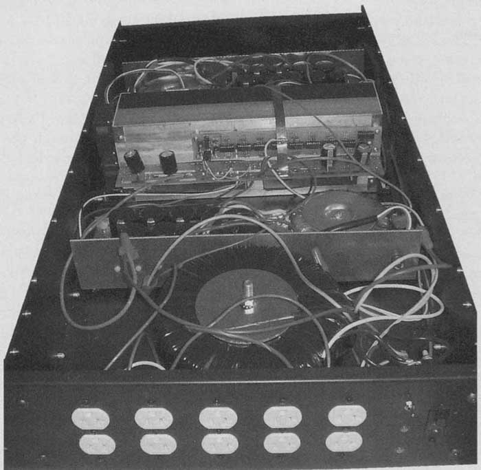
PHOTO 1: Inside the cleaner unit.
Using the generator with the internal gasoline motor showed that the output varied a bit with the load both in level and frequency. This is not very green and not a very good approach.
There are complete commercial units designed to convert single-phase 220V AC service to 230V three-phase. The smaller units are just capacitor based, but the larger units are motorized. One of these could be the basis of an off- the-shelf solution. However, the hid den components in an AC generator or alternator cause distortion. So you may still want to use a cleaner such as the resonant filter.
Of course, you should not rule out the other options of a wind-, solar-, or water-powered generator. Making your own clean green power might not be a bad idea.
If you are tempted to play with one of these approaches to cleaning your power line, you may wonder how these affect the quality of the reproduction of music?
Bigger and more expensive does not need to correlate with quality. The simple voltage stepup transformer is a good choice if you are listening with loud speakers of limited efficiency. You can use the unit as a stepdown with older classic gear to get it back to the design voltage.
The resonant filter is probably the best cleaner for the buck, but it does make some acoustic noise. I also don’t like that the inductors are not rated for this use. I also found that some gear does not sound as good with a pure sine wave. It seems the third harmonic distortion adds more charging time to the power supply and improves sound quality!
The isolation transformer boosts the voltage and cleans up the line. This improves sources and preamps as well as the power amp.
The complete regeneration of the AC line as in the 300W version is probably the least cost-efficient and least green version of all the cleaners. To get around this problem I am currently setting up a windmill to use the 300W version to power my class A system. Almost an eco-friendly compromise!
The corrected AC regulator is probably the best at doing the job. Keep in mind the one I built is able to provide 20A. This same design can be made much more economical if you design one for 600 to 750W.
The motor generator is the most powerful of the approaches because it’s the simplest and can be combined with other energy input sources. It’s not the best sounding from my simple trial. The best solution is a well-designed power supply in the audio gear itself.
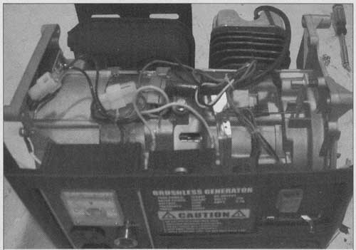
PHOTO 2: Gas-powered AC generator.