By combining a classic cascode schema with a balanced technique, you can successfully build an outstanding RIAA preamplifier.
Why did I use the word “outstanding” instead of “Hi-Fi” or “Hi-End” in the introductory blurb? Maybe because those fancy words have lost their meanings. “Hi-Fi” now suggests that such equipment is a bit better than the cheapest, and “Hi-End” now assumes the lost meaning of “Hi-Fi.”
Well, “Hi-End” is used so often and not always appropriately, so it is already closer to “high tech” or “high priced,” rather than about quality of sound. A good friend of mine has the idea of applying the term “Hi—Art” to equipment of outstanding quality. It is probably a good idea; however, no matter what definition I use I am still talking about the same thing: equipment of good sound and musicality.
I did not try to build here a preamplifier with precision RIAA equalization or lowest possible distortions, but I did much to make its sound dynamic, transparent, and musical. Why did I do this now, after I made Retro DAC (“A Balanced Non Oversampling Retro DAC” )? I wanted to compare sound reproductions of CD and record players, and will reveal the results later in the article.
CONNECTING CARTRIDGE TO AMPLIFIER
The input impedance of a vinyl amplifier needs to be 47k-ohm and 200-600pF for practically all moving magnet (MM) cartridges. This input capacitance is the sum of several others, such as the capacitance of interconnect cable and input capacitance of the first stage.
Designers suggest that you add an input capacitor when input capacitance is not sufficient; however, this is not always done in practice.
So, how exactly do cartridge manufacturers want you to use their product? Ac cording to recommended impedance they do not want you to use it as a pure voltage source, but partially a current one. Let me explain this.
On the one hand, the cartridge electrical equivalent is a serially connected voltage source, resistor, and inductance, and average values of the mentioned resistor and inductance are about 1K and 400mH. Cartridge inductive reactance is low at low frequencies and it increases with increasing frequency. The standard load for the cartridge is 47K-ohm; therefore the cartridge impedance is much lower at this value at low frequency and equal or even higher at high frequency. It means at low frequency the cartridge works as a voltage source and at high frequency, when impedances of cartridge and its load are almost equal, it becomes a partial current source.
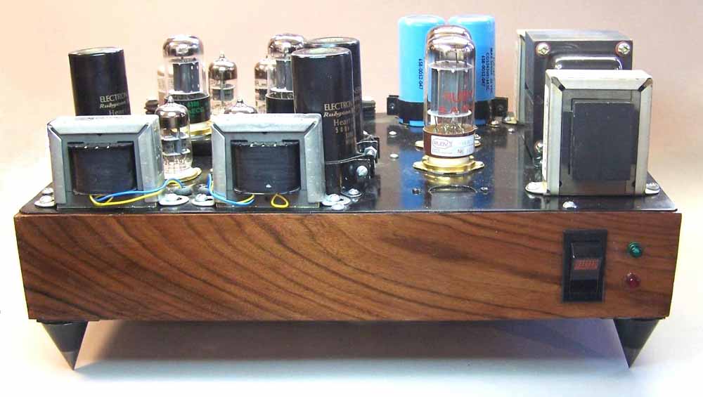
PHOTO 1: Front view.
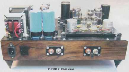
PHOTO 2: Rear view.
On the other hand, the cartridge is a reversible electromechanical system, surprisingly similar to any speaker or DC electric motor. It means it produces an electrical signal when the stylus moves and vice versa it produces stylus movement when the signal goes to the coil. Thus, when load impedance is about equal to cartridge output impedance, the current, generated by the cartridge, goes through the load and returns to the coil, affecting stylus movement on mid and high frequencies exactly as low output amplifier’s impedance dumping movement of speaker’s cone. Ever cartridge has its mechanical resonance at high frequency and, I believe, the reason for the suggested connection is to dump this resonance to make high frequency response more flat. The only problem in the suggested connection I see here is the usage not only of a capacitor, but also a resistor, which affects reproduction at mid frequencies. A simple experiment proved this.
I increased input resistor value 20 times and listened to the difference. The ad vantage of this connection method was significantly improved signal dynamic.
• Dramatically increased high-frequency level was the disadvantage. The suggested way of connection brings harm to mid frequencies and improves high frequencies, at least to my ear. It needs to be connected another way.
• First, I decided to eliminate the input resistor completely by using an input transformer; second, I needed to bring a capacitor to restore the high-frequency load to the input stage. My cartridge now is an Ortofon OMB and the value of the input capacitor C is 410pF. Another cartridge may require another capacitor’s value, and this is a very good place for the audiophile to play.
HUM, MICROPHONIC EFFECT, AND NOISE
A low output signal of the MM cartridge causes several types of distortion: hum, microphone effect, and noise.
Hum is rather easy to handle. DC power supply for the tube heater, proper shielding, and input transformer can duce it significantly to the level you may not need to worry about it.
Microphone effect is a more serious obstacle. Some tubes have a lower level of it, some have a higher level, and some tubes from the same manufacturer may even have significantly different levels. I’ll tell you how to reduce this effect in the construction part of this article.
Noise is not a big deal for tubes there. I cannot guarantee absolute silence when you put your ear against a speaker; however, its level is 15-20dB lower than the noise of an absolutely new record.
INPUT STAGE
There exists several possible input schema configurations.
Pentode schema. High gain, rather low noise level. It is possible to produce a two-stage preamplifier. The main disadvantage is a high level of distortion; it produces not only 2nd and 3rd harmonics, but up to 7th-order. It is also very critical to change load impedance, which sets some limitation on using passive RIAA equalization.
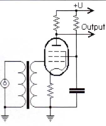
FIGURE 3:Pentode input.
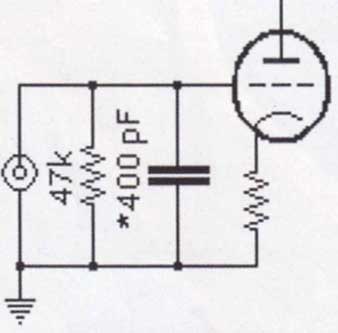
FIGURE 1: Suggested connection.
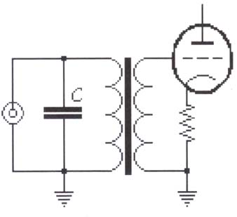
FIGURE 2: Modified connection.
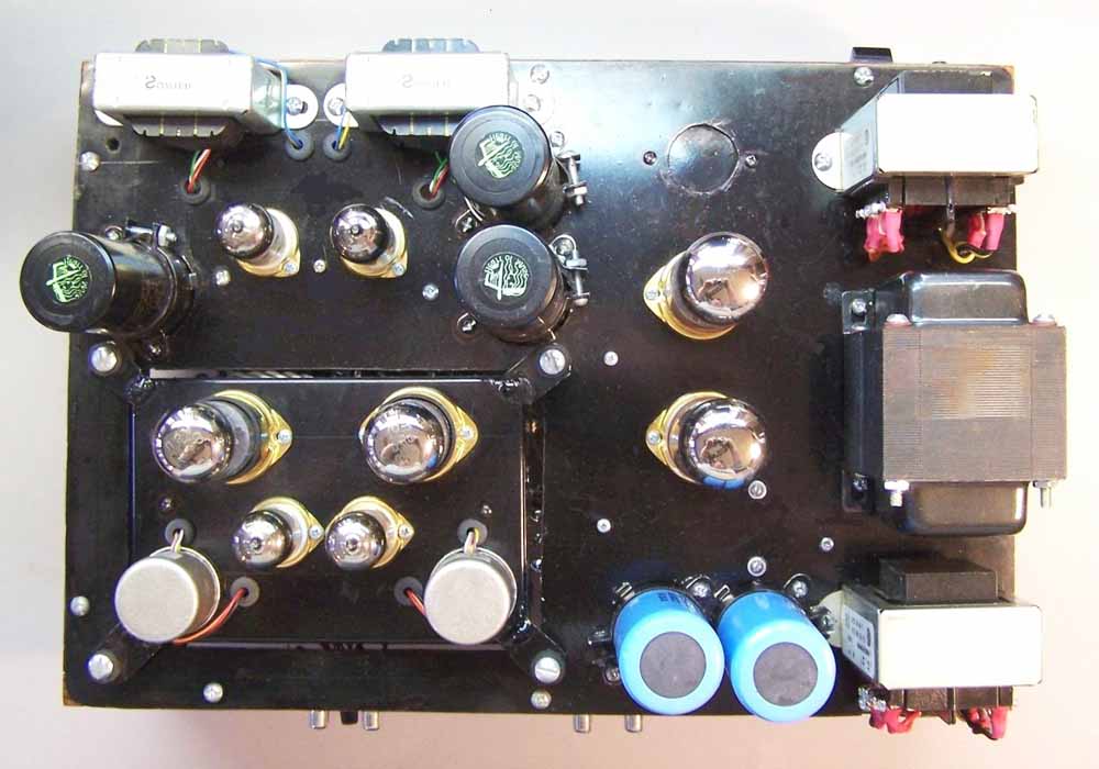
PHOTO 3: Top.
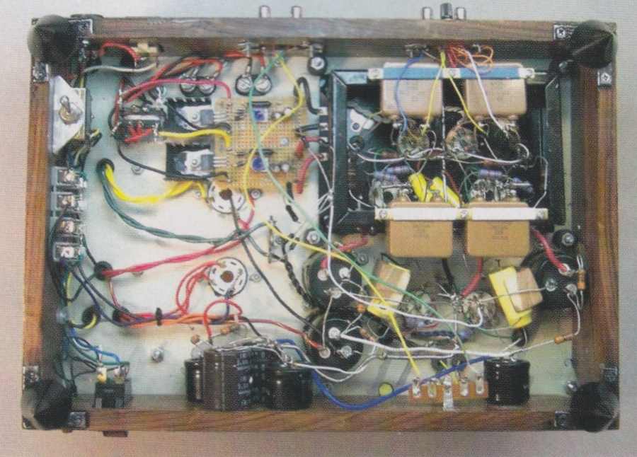
PHOTO 4: Bottom view.
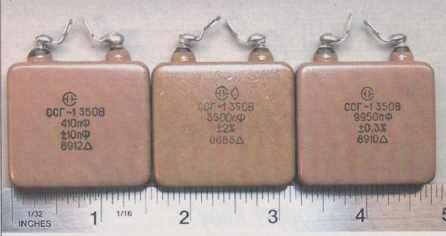
PHOTO 5: SSG-1 caps.
Triode schema. Almost the best, with low distortion and low noise; however, low gain of this schema requires three stages of amplification, which is obviously not good. It is preferable to have only two.
SRPP (series regulated push-pull) schema. It is very fancy nowadays. Gain is slightly higher than triode. The main advantage is low output impedance, but it offers no benefit for the input stage. The main disadvantage is local negative current feedback.
Cascode schema is my choice. It has pentode gain, triode linearity; and perfect frequency response. High output impedance and the unique property of having good linearity even under low impedance load allows you to use this schema for simplifying RIAA equalization. I’ll tell you more about this later.
BIAS AND BALANCED SCHEMA
Realizing bias warrants further discussion. Regular cathode resistors in all of these schemas produce local negative feedback, which reduces gain and also makes any schema sound worse to my ear.
Simply shunting this resistor with a capacitor is actually not good because of the high dependence on the quality of this capacitor. Even the best of Black Gates are not good enough here.
Another idea is to use a ni-cad rechargeable battery instead of the resistor. This is a good arrangement because bias is absolutely equal to battery voltage. But it does not offer any bias adjustment and this is why you should not use this solution.
It is also possible to use a special power supply, but this is one of the worst solutions because sound quality still depends on all parts—capacitors, diodes, regulators, and so forth—of the power supply. It is also more complex and expensive. The only real solution to this problem is a balanced schema.
Direct currents of both rails flow in the same direction adding to each other, producing proper bias on a common-cathode resistor. However, alternative currents flow in opposite directions: input signal in balanced, class A schema increases plate current in one rail and reduces—at the same time—plate current in the other rail for the same amount, therefore the common- cathode resistor voltage drop is not affected by the signal and it means this schema does not produce local negative feedback. Practically, the rails’ misbalance is about several percent, and this is a natural way to eliminate negative feedback.
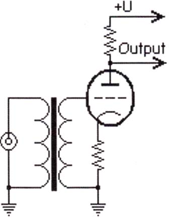
FIGURE 4: Triode input.
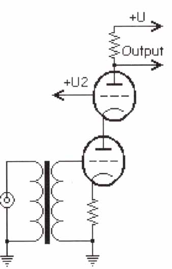
FIGURE 6: Cascode schema.
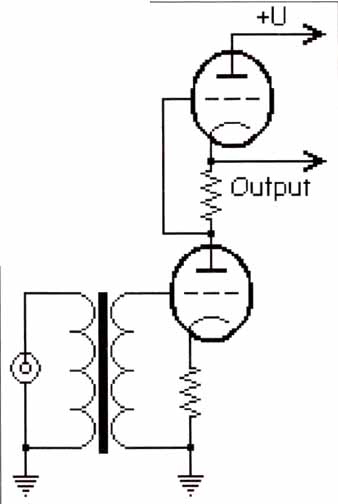
FIGURE 5: SRPP schema.
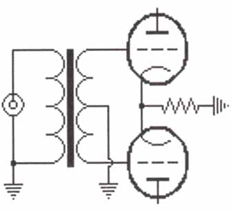
FIGURE 7: Balanced schema and bias.
RIAA EQUALIZATION
I used the application of passive RIAA realization from the article “On RIAA Equalization Networks” by Stanley P. Lipshitz. There is nothing new except one thing: I wanted the advantage of using balanced cascode schema.
First, high output impedance of the cascode schema can play the role of resistor R1. Of course, output impedance is not absolutely equal to the calculated value of R1, but it is rather close and the only practical difference is the level of lowest frequencies, which is not that critical. Second, this schema connects between two cascode outputs and the output signal to balanced output stage.
This is the most critical place in the whole preamplifier. The highest quality parts available are needed for this circuit.
OUTPUT STAGE
Balanced Schema. This is also nothing new. I used a slightly changed schema of the analog part from my balanced DAC. The difference is that I eliminated the negative power supply and used 6922 tubes. This transformer output is good for production of a 600fl line to connect to the amplifier.
Preamplifier Schema. I show operating voltages for reference only. You do not need to set the exact voltage value, and 30% tolerance is absolutely fine.
Power supply. There is nothing new in this schema either. The only secret is good quality parts for good sound.
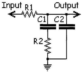
FIGURE 8: Standard passive; RIAA equalization.
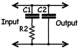
FIGURE 9: Modified passive RIAA.
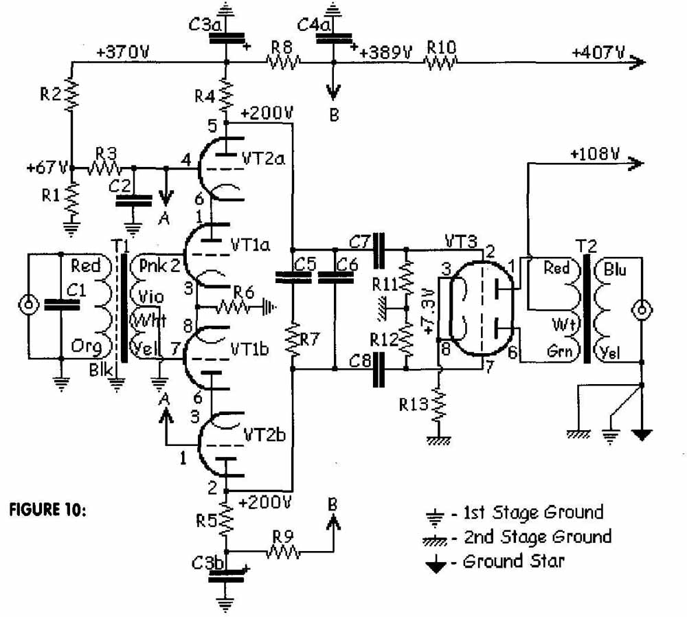
FIGURE 10: One channel of RIAA preamp.
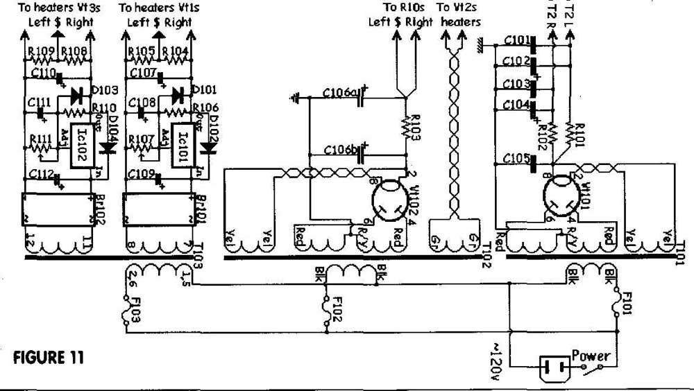
FIGURE 11: Power supply.
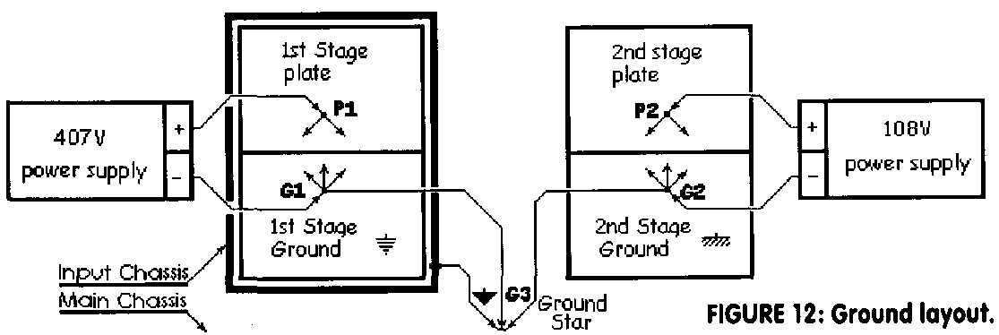
FIGURE 12: Ground layout.
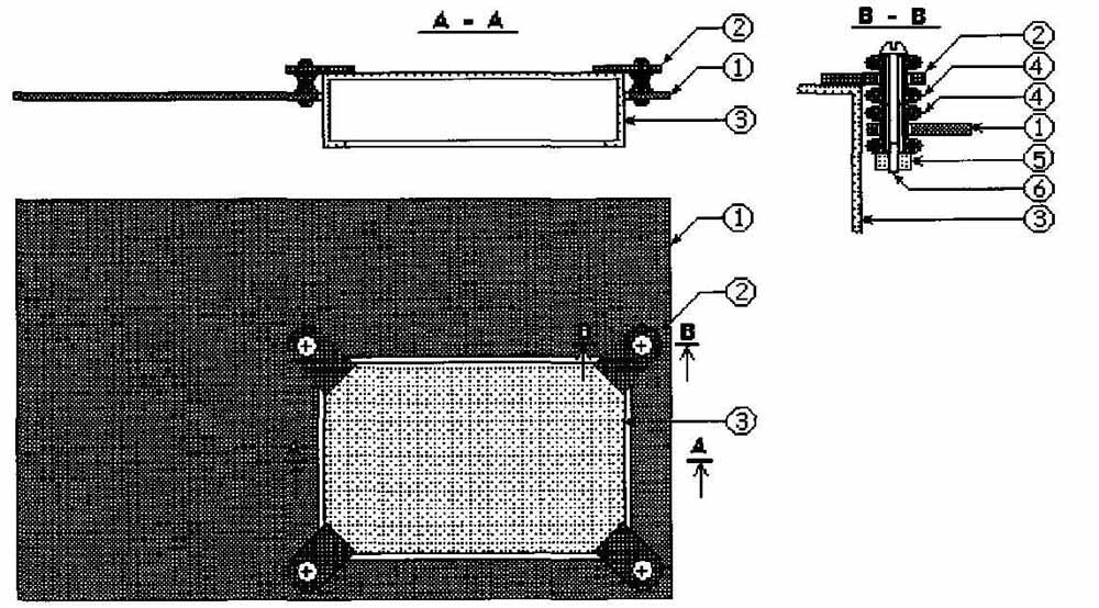
FIGURE 13: Both chassis— main and preamplifier.
GROUND AND POWER SUPPLY LAYOUT
This part is rarely explained and deserves additional attention.
You connect all first stage ground wires of both channels to a point G1: transformer T1, resistors R1, R6, capacitors C3, C9, C10, and negative 407V power sup ply. Both resistors R10 and positive 407V power supply go to a point Pi. All second stage ground wires go to point G2: resistors R: R12, R13, secondary T2, and negative 108V power supply. Both taps of the T2 primaries and positive 108V power supply go to point G2.
Then you connect points G1 and G2 to point G3 and only at this point do you connect it to the main chassis. The input stage chassis is electrically connected to the main chassis with only one wire.
CONSTRUCTION
Numbers in parentheses refer to Fig. 13. You should make the input stage on a separate chassis (3) and suspended against the main chassis (1) on rubber grommets (4) for vibro-isolation. Solder four mounts (2) to the corners of the input stage chassis. Use two grommets on each corner to make this suspension softer. Screw (6) through the grommets and fasten with a nylon insert lock nut (5). I used grommets from laser pickup suspensions.
The rest of construction is similar to the Zero-oversampling RetroDAC which used 15” x 10¾” steel sheet for the main chassis and put it on a wooden frame, which I glued before and put steel angles on the bottom side of this frame for rigidity. For further vibro-isolation I put all construction on speaker spikes. This greatly reduced the possibility of microphone effect.
All wires that go from the main chassis to the input stage chassis must be as soft as possible. Tester probe wire is a good choice. Grounds are made of 8 gauge (about 3.5mm) solid copper wire. All heater wires are made as twisted pairs.
Black Gate capacitors C3, C4, and Ci06 are pretty tall, about 5”, and may increase the total height of the preamp. To avoid this I drilled holes in the chassis, put caps through, and leveled them with other tubes arid capacitors.
STARTUP:
The tune-up procedure is simple:
1. Do not connect any interconnect cables. Remove all tubes.
2. Use potentiometers R107 and R111 to set output voltages of tube heater regulators to 6.3V on pins 4 and 5 of tube sockets Vt1 and Vt3.
3. Check all necessary AC voltages.
4. Turn unit off, put in all tubes. Turn on and wait for 10-15 minutes allowing warmup for all tubes.
5. Check heater voltages again on Vt1 and Vt3 and make necessary adjustments with R107 and R111 if needed.
6. Make sure you follow all DC voltages, as shown on the schema. Attention! Vt2a and Vt2b plate voltages cannot be measured with a low impedance voltmeter because of high output impedance of the cascode schema. You must use a high input impedance voltmeter, at least 50 milli-Ohm.
7. It is a good idea to keep this unit on for several hours before listening. Electrolytic capacitors need this time for forming. Of course, you can begin to listen immediately, but realize that the sound will be no good at the very beginning but will improve each hour. It took at least 50 hours to fully complete forming the capacitors to my liking. There is no need to keep the unit on for 50 straight hours without turning it off Forming accumulates and in a week of listening will be completed.
8. Turn off, plug in interconnect cables, turn unit on.
FINE-TUNING
I already mentioned about playing with the value of capacitor C1, which is very important. Now here’s what you can do with the RIAA equalization circuit: C5 and C6. Take several capacitors of the same values but different types: 10,000pF and 3300pF or close values. Changing them will not change the frequency response of the unit; however, its sound will change dramatically. There are only three types of capacitors I can recommend: silver mica, tin and Teflon, and copper and paper in oil. Frankly, I did not try silver and paper in oil.
It has become good practice to locate audiophile-grade parts among old Russian military production. This is also the route I plan to follow and want to introduce you to another type of silver mica cap. Their types are SSG-1, SSG-2, and SSG-3, with values from 150pF up to 200,000pF, all rated 350V, and with absolutely stunning tolerance from 2% up to 0.3%l
They look pretty conservative, but the biggest advantage, of course, is the out standing sound. I compared sound with regular silver mica, Teflon TFT Relcap, and Jensen copper and paper in oil in place of C5 and with no hesitation put SSGs in place of C1, C5, and C6. You can find some of them on eBay. Of course, you may prefer another sound and different capacitor types.
Another place to change sound dramatically with no change in frequency response is to play with plate power supply capacitors C101/C102 and C103/C104. Each of these capacitors has summary capacitance of about 1000uF. Why did I make each of them out of two different capacitors:820 uF Nichicon and 220 uF Black Gate? I decided this after much listening.
With just the 1000uF Nichicon cap, the unit sounds as though it is going through curtains. Using just such capacitors affects the sound quality of high frequencies. Black Gates sound perfect, however making a 1000 battery from just them is an economical disaster. So I decided to mix them up to make it more affordable and get good sound balance at the same time.
Try the different types of capacitors and experience different sounds, some of which you may like. Tastes differ.
HOW DOES IT SOUND?
In the beginning of this article I promised to compare the sound of my DAC and phono preamplifier. Here are some surprising results.
First, I used the same CDs and LPs to listen to the same songs on both units. The DAC sounded more transparent, with better stereo separation of channels. Vinyl had better musicality of program and delivery of musical impression. In other words: the DAC produced more precise but cold sound while vinyl sounded more warm and moody.
Use the DAC when you want to hear some background instruments or voices. And use vinyl for listening to the music.
So which one is better? I would say each of them is good -- in its own way. I am going to use them both, because of their “outstanding quality.”
One last word: In my real phono preamplifier, I used power-supply schemas exactly as I did before in my RetroDAC with no output stage plate transformer. I just wanted to show you a regular way of doing this and introduce different options.
The rest of this phono preamplifier is as described here.
REFERENCES
• 1. “On RIAA Equalization Networks,” Stanley P. Lipshitz, J. Audio Eng. Soc., 1979, Vol.27/6.
2. “Completely Balanced Non-oversampling RetroDAC”
TABLE 1: PARTS LIST.
Position |
Value |
Manufacturer |
BR101, BR102 |
5A |
Any diode bride 5A or more |
|
|
|
C1 |
410 pF |
Silver Mica SSG-1 |
C2 |
0.22μF 600V |
Hovland Musicap |
C3, C4 |
100+100μF 500V |
Black Gate WKZ |
C5 |
0.01μF 400V |
Silver Mica SSG-1 |
C6 |
3300 pF |
Silver Mica SSG-1 |
C7, C8 |
0.22μF 400V |
0.22μF TFT Relcap + Silver Mica SSG-1 3600pf |
C101, C103 |
220μF 160V |
Black Gate NH |
C102, C104 |
820 μF 200V |
Nichicon GK |
C105 |
68μF 350V |
Black Gate NH |
C106 |
100+100μF 500V |
Black Gate WKZ |
C107, C110 |
100μF 16v |
Any |
C108, C111 |
1μF 16v |
Any |
C109, C112 |
23000μF 16v |
Mallory |
|
|
|
F101, F102, F103 |
1A 250V |
Any slow fuse |
|
|
|
Ic101, Ic102 |
LM338T |
Any |
|
|
|
R1 |
20K 0,5W |
Tantalum |
R2 |
100K 2W |
Tantalum |
R3 |
2M 0,5W |
Tantalum |
R4, R5 |
120 K 1W |
Tantalum |
R6 |
600 Ώ 0,5W |
Tantalum |
R7 |
33k 1W |
Tantalum |
R8, R9, R10, R101, R102 |
3.3K 1W |
Tantalum |
R11, R12 |
1.0 M 0.5W |
Tantalum |
R13, R103 |
2.2K 1W |
Tantalum |
R104, R105, R108, R109 |
470ohm 1W |
Any |
R106, R110 |
120ohm 0,5W |
Any |
R107, R111 |
500ohm 1W |
Any potentiometer |
|
|
|
T1 |
8920 |
Sowter, UK |
T2 |
8650 |
Sowter, UK |
T101 |
263AX |
Hammond |
272DX |
Hammond |
|
T103 |
185D16 |
Hammond |
|
|
|
VT1, VT3 |
6922 |
|
VT2 |
6188 |
|
Vt101, Vt102 |
5AR4 |
|
|
|
|
Steel Chassis |
1441-8 |
Hammond |
Speaker spikes |
DSS4 |
Dayton |