Adding a phase angle meter to your test bench can make your life a whole lot easier.
A phase angle meter is useful in audio work to determine the phase shift between a reference signal and a phase-shifted signal, both having identical time periods. Typical uses include:
• Finding the phase angle between voltage and current to determine the phase shift and impedance of a loudspeaker over its frequency range.
• Finding the phase shift between the input and output voltage of a tube amplifier to establish the HF (high frequency) and LF (low frequency) cut off points needed to avoid instability in feedback amplifiers.
If you need to measure phase angle, you can do it with an oscilloscope, but it’s a tedious process. You must display the two sine waves on the scope, and place the time base in the uncalibrated mode with the reference sine wave positioned so its start and finish zero-crossings exactly span the frill ten horizontal divisions on the screen. Each division represents 36°. For small phase angle differences, you can position a half-cycle over the ten horizontal divisions, so each major division will represent 18°.
Next, while triggering on the reference sine wave for display stability, you measure the time difference between the reference and variable sine wave same- direction zero-crossings and convert that number of divisions to degrees of phase shift. You must also determine—by relative position—whether the variable sine wave is leading or lagging the reference. You must use the chop mode—not al ternate—so the two sine waves are synchronized in time.
Some very expensive digital storage oscilloscopes (DSO) have the processing power to do this work for you, but for most hobby- oriented analog scopes, you need to perform the above steps for each frequency of interest. The scope needs to have a wideband frequency response of at least 100MHz for a 50kHz sine wave measurement range. At low frequencies, the relatively long display blanking time will make the measurement difficult. At high frequencies the dimmer trace intensity will make the measurement equally difficult. A PC-based storage oscilloscope eliminates these problems and, if it has cursors you can position on the time axis, can eliminate any rough interpretation of an analog display and provide a more exact determination of the phase shift.
Over a year ago I won a Phase Meter PM-720 analog phase angle meter on eBay. The date codes on the parts indicated it was made about 1965. Because I couldn’t find any documentation on the unit, I spent a fair amount of time reverse-engineering the schematic from the circuit board layout. Some of the circuitry was sealed in a potted module that plugs into the main circuit board.
I intended to restore the PM-720 to full working condition, but needed a method of accurately varying the phase angle of one sine wave with respect to another fixed reference sine wave. This article describes the fairly simple circuit that I made for this purpose. Parts cost is about $41. You can also use it to calibrate the Analog Phase Angle Meter by Vern Mastel in the 4/1980 issue of TAA Another analog phase angle meter candidate is the HP 8413A phase-gain meter, often available on eBay.
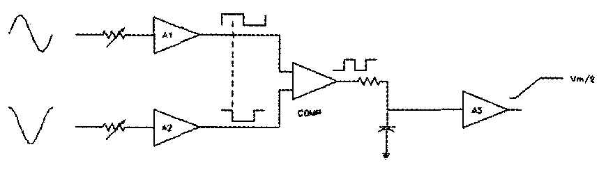
Above: Fig. 1 Phase Angle Meter block diagram.
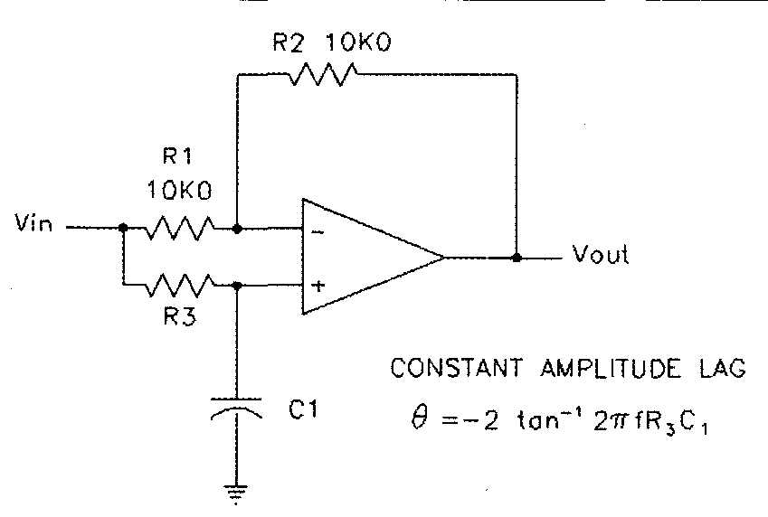
Above: Fig. 2: Generalized all-pass circuit.
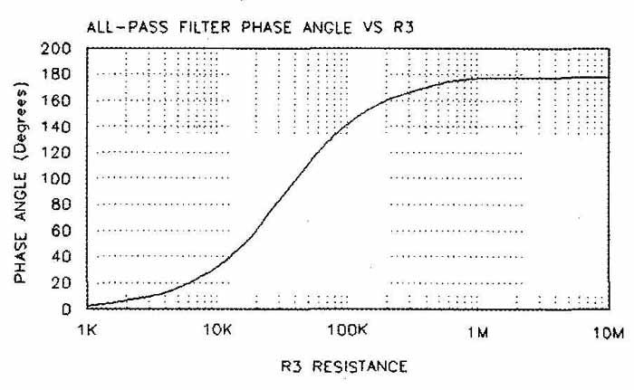
Above: Fig. 3: Ali-pass lag angle vs. R3.
PHASE METER BASICS
The block diagram for the PM-720 in Fig. 1 is fairly typical of the operation of an analog phase angle meter. The reference and variable sine waves are input to A1 and A2, which amplify (if necessary) the sine waves and convert them to phase-accurate square waves. The variable co sine wave in the diagram lags the sine reference by 90°. A comparator extracts the phase angle difference and applies the result to an integrator that produces a DC voltage that is linearly proportional to the phase angle between the two sine waves.
A3 buffers and scales the integrated signal and applies a zero-level (in-phase) calibration offset if required. Logic circuit flip-flops (not shown) receive the same square waves that are input to the comparator and determine whether the variable sine wave input leads or lags the reference sine wave.
Modern digital phase angle or gain-phase meters can do this and so much more with their DSP capabilities. You can also determine power factor, lead-lag compensation, phase-gain margin, watts, VARs, voltage ratios, Bode plots, and so on.
The PM-720 designers had a very limited availability of ICs in order to perform the various steps needed to produce the phase angle measurement. As such, most of the circuitry is discrete, with over 170 parts in the unit, many of them germanium transistors. Today you can build the same or better capability with far fewer parts.
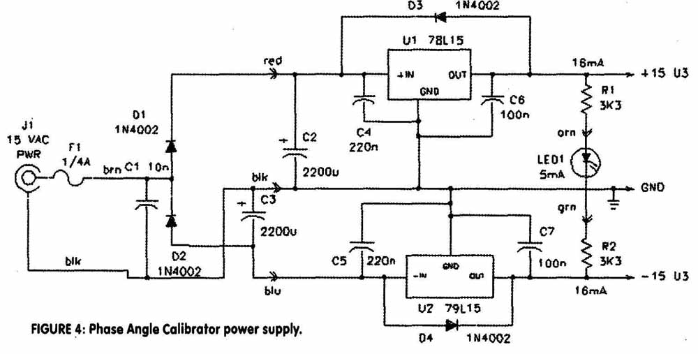
Above: Fig. 4: Phase Angle Calibrator power supply.
The PM-720 was quite sophisticated for its era, with a frequency range of 1MHz and an input voltage range from 1V RMS to 500V RMS. The analog display meter had four ranges of 1800, 900, 36°, and 12° full-scale. It also provided an analog output voltage proportional to the 180° range meter reading. There are a myriad of trimpots for output, zero ad just, balance between lead and lag phase input, and so on.
The discrete power supply takes up half the PC board, with +12, +6, +3.6, -6, —12, and —18V supplies needed for the various functions. These were de rived by discrete transistor regulators or zener diodes from ±25V DC raw supply rails. All the aluminum caps in my unit were shot and in need of replacing. Two were leaking electrolyte, which was fortunately contained under the plastic sleeves.
The analog inputs are sent through frequency-compensated input attenuators and applied to a level-shifting discrete FET/bipolar amplifier circuit, then converted to square waves by two Fairchild j comparators. These were the first integrated comparator ICs, ran on +12V and —6V supply rails, and also required a power-supply ground reference connection.
The lead/lag indicating circuit is composed of five Fairchild uL91429 dual 2-input NOR gates of RTL (resistor-transistor logic) in 10-lead TO-5 can packages. RTL was the first integrated circuit logic family (years prior to DTL and TTL), which ran on a +3.6V DC sup ply. These basic NOR gates are used to produce the required inverters, one-shot gate, and RS flip-flops. The logic drives two germanium transistors that, in turn, drive the 28V LEAD or LAG indicator lamps.
The reference and variable square waves are then applied to level shifting circuits that convert the reference square wave to 0 to +1.7V, and the variable input square wave to -10V to +0V. These two square waves are applied to the pot ted module along with the zero adjust offset derived from the +12V supply. The integrator 0 to +3.6V DC voltage comes out the back of this module, and represents a 0 to 180° meter reading. There are four trimpots that calibrate the full-scale readings for each of the PM-270’s meter ranges.
The 0 to 3.6V signal is also supplied to another trimpot that can convert the full-scale signal to whatever maximum up to +3.6V that pleases you. I chose to calibrate it for 0 to +1.8V for use with my DMM, whereby 1.5V is equivalent to 180°. The integrator has a fairly long exponential time constant, so phase angle readings at 1kHz can take about five seconds to settle to full scale.
The mystery potted module may contain an op amp, based on the responses I observed at the output from the input signals I applied. The +12 and -12 power supplies are furnished to two of the module connector pins. It’s too small to hold very many discrete transistors, and there were only two solid-state monolithic opamps available in the 1965 time frame.
The first, designed by linear IC genius Bob Widlar, was the uA702 produced by Fairchild Semiconductor (FSC) begin- fling in 1963. It had the same +12 and —6V supply voltages as the uA710 comparators used on the PM-720 main PC board, and the date codes on the 710s were 532 (32nd week of 1965, using the generally accepted industry date coding). The Fairchild high gain-bandwidth uA709 (also designed by Widlar) had just come out in 1965, so it probably wouldn’t have been available during the PM-720 design cycle. Either op amp would have been quite expensive in 1965. If I am correct that this module contains one of the early op amps, it may have been potted inside to hide the integrator design details from perceived competitors. Or I could be totally wrong.
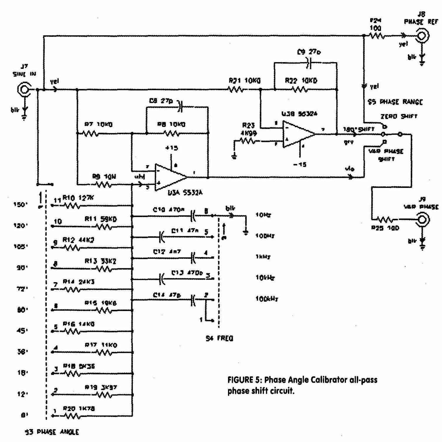
Above: Fig. 5: Phase Angle Calibrator all-pass phase shift circuit.
Bob Pease of National Semiconductor said these original uA702 and uA710 FSC designs used crude NPN monolithic technology which was all that was available back then. They used +12V and —6V supplies so as to not exceed the overall 18V breakdown rating. The uA702 was a poor performer, and was out of production by the mid-1980s (the last listing I have in my 1987 Fairchild Linear catalog shows support for only the Military uA702QB package).
The 702 and 710 circuits used mostly load resistors pulling up to +12V, and pull-down resistors to —6V. Most of the signal processing was done between the zero volt ground pin and +6V. The output swing was in the range 0 to +6V. For its day, it was considered fairly bright.
When the RA709 came along, with its 36V breakdown ratings it could happily run on ±15V supplies.
Texas Instruments also made versions of these devices. Bob didn’t mention whether National ever made the 702, but Widlar went to work for NSC in 1966 and designed the much improved LM101 and LM107 op amps.
HOW THE CALIBRATOR WORKS
The Phase Angle Calibrator makes use of an op amp filter circuit called the all-pass circuit, which takes a sine-wave input and produces a constant amplitude phase-shifted sine wave output. The lag output version is shown in Fig. 2. You can produce a leading phase-shifted output by interchanging R3 and C1.
The theory behind the all-pass filter is available in many reference books and texts, but I found one by Walt Jung that I believe is the easiest for a novice to understand. The phase shift angle is varied by R3 and C in accordance with the formula:
theta = -2 tan^-1 2*pi*f*R3C1
…where 0 is the phase angle, and f is the frequency. After selecting a suitable value for C you can solve for R by rearranging the formula:
R3 = tan(-theta/2) / 2*pi*f*C1
This is hardly a linear relationship, as notice by the graph in Fig. 3. Large changes in resistor value produce very little change in phase angle as you approach 0° or 180°. It’s much easier to apply the input signal to both inputs of the phase angle meter for 0°, and use an op-amp inverter to generate the 180° signal. You also need to multiply the value of C1 by 10 for each decade decrease in frequency to retain the constant amplitude feature of the all-pass filter.
The schematic diagram for the Phase Meter Calibrator power supply is shown in Fig. 4. The J1 power source is a 15V AC plug-in AC adapter, so there is no on-off power switch.
D1 and D2 each half-wave-rectify the 15V AC into roughly ±2W DC. C2 and C3 are the main reservoir caps, and U and U2 are linear regulator ICs that provide ±15V DC at the supply rails for the all— pass phase shift circuits. C4 and C5 ensure stable operation for the regulators. LED1 is the power-on indicator. Fuse F1 protects the power supply AC adapter. C6 and C7 are the local bypass caps for the all-pass circuit opamp.
The schematic diagram for the all-pass phase shift circuit is shown in Fig. 5. A sine-wave signal generator is applied to J7. The calibrator can handle up to 7V RMS of input signal. This becomes the reference sine wave that is connected to J8.
Op-amp U3A is the all-pass filter. S3 selects a phase shift angle from 6° to 150°, and S4 selects a frequency range from 10Hz to 100kHz. The phase angles I chose for S3 are optimized for the four ranges of operation of the PM-720, but you can change the resistors to meet your individual requirement, in accordance with the formula shown earlier to solve for R3.
S5 applies the input sine wave to the variable output jackJ9 for the zero phase shift condition. In the second 180° phase shift position, the input sine wave is processed through unity-gain inverter U3B. The variable phase shift position of S5 selects the output of the all-pass circuit U3A. The two output jacks have series 100-ohm resistors to protect against accidental shorts. The input source signal generator should have a low output impedance of no less than 600-ohm.
CONSTRUCTION
The drawing for my chassis is shown in Fig. 6, along with the rear views of the rotary switches I used. I built the calibrator circuitry on two wire-wrapped perfboards for this project. In keeping with good assembly practice, solder in the least sensitive parts first (resistors, then capacitors). Then install the regulator ICs and other semiconductors last.
Double-check the orientation of the polarized components. I used a low-profile IC socket for the op amp, and checked for the proper power supply voltages at the socket before plugging in U3.
Photo 1 shows the top view of my Phase Meter Calibrator chassis. The switches and banana jacks on the left side are associated with a transistor matching circuit that is not part of the subject calibrator (for details see www.passdiy.com/articles.htm, transistor matching). The lettering was made on transparent adhesive-backed drafting appliqué film, as is my usual practice.
The sine wave input jack J7 is at the top, while J8 and J9 are on the right side.
Photo 2 shows the internal wiring. The raw DC supply, power jack, and fuse are in the bottom part of the chassis on the left in the photo. The switches, DC regulators, and op amp are located in the top half of the chassis, on the upper-right side of the photo.
The unrelated transistor matching jacks and switches are on the lower right in the photo.
I used tapped nylon spacers to mount the perfboards to the chassis. I used 40 spacers on the raw DC supply board and cut the wire-wrap pins short because of the depth of the rotary switches. The op-amp board uses ¾” spacers and full-height pins. The resistors and caps that control the phase shift are mounted on their respective rotary switches.
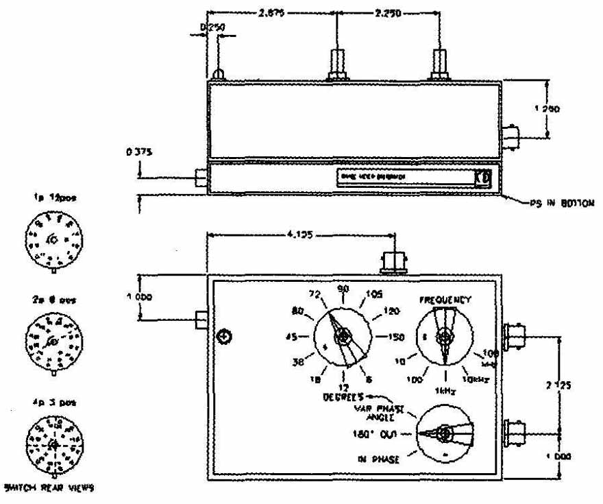
Above: Fig. 6: Phase Meter Calibrator chassis.
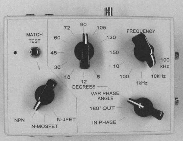 PHOTO 1: Phase Meter Calibrator top view.
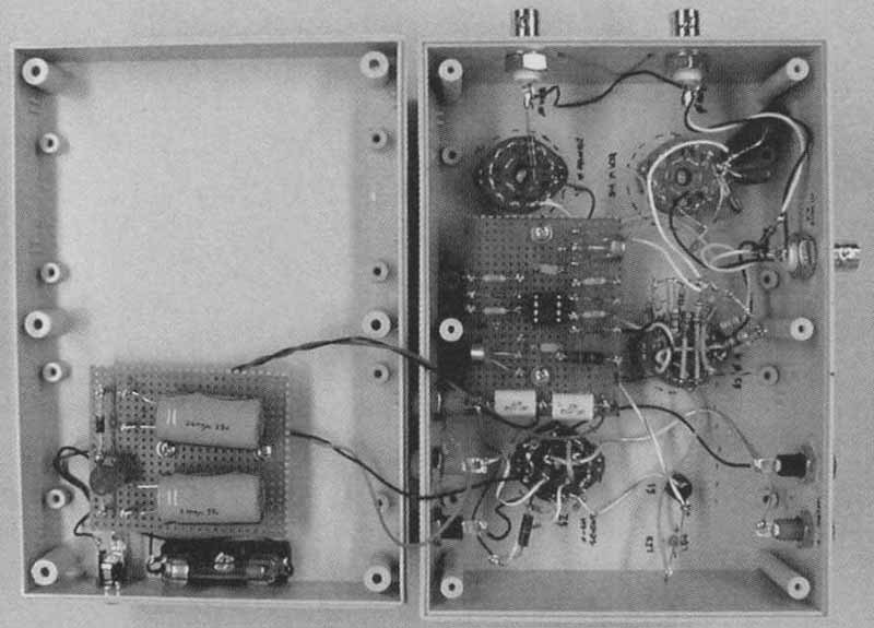
PHOTO 2: Phase Meter Calibrator
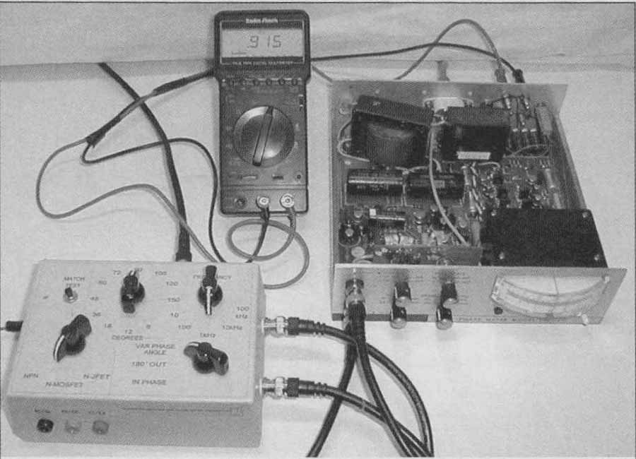
PHOTO 3: Phase Meter Calibrator
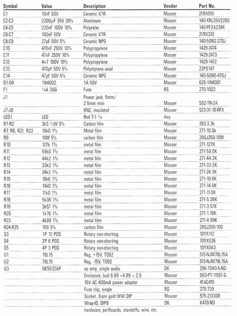
TABLE 1: PARTS LIST. Symbol—Value—Description—Vendor--Part No.
USING THE PHASE METER CALIBRATOR
Photo 3 shows the calibrator in use with the PM-720 Phase Meter. The input signal is a 1kHz sine wave, and the calibrator is set for 90°. The PM-720 shows the needle centered on the 180° FS range. My DMM is connected to the analog output jacks and shows a reading of 91.5° (0.915V DC). The red power lamp and blue LAG lamp can also be seen below the meter.
The PM still has its original aluminum filter caps at this point. As soon as I verified that the unit was filly functional, I replaced all the aluminum caps with Mouser Xicon TG high tempera ture axial lead caps.
R9 is always in-circuit and gives approximately 180° phase shift, although at this extreme the gain is dropping from unity and the distortion is higher. Be cause of the asymptotic approach of the required resistor values to the 0° and 180° phase angles, you may need to select different values of R10, R11, R19, and R20 while using an oscilloscope to verify the phase shift. C14 (100kHz range) is only 47pF, and suffers from any parasitic capacitance in the wiring. Again, I needed to select C14 from a number of different NPO caps to get a reasonable 3% accuracy at the highest range.
SOURCES:
- Digi-Key Corp.
- Mouser Electronics
- Radio Shack
REFERENCES:
1. “An Analog Phase Meter,” Vern Mastel, 4/80 TAA, pp. 12-16.
2. “Simple Phase Meter Operates to 10MHz,” Ron Mancini, Intersil Application Note AN963 7.1 ( 10/27/2004).
3. Audio IC Op-Amp Applications, 2nd Edition, Walt Jung, Howard Sams, Para. 5.3.7 All-Pass Circuits, pp. 164-165.