|
|
.This push-pull, self-bias, class AB1 amp performs well in both the ultralinear and triode modes.
The sensitivity of this amp is 0.4V RMS for 28W triode or 0.48V RMS for 50W ultralinear (UL) output. It has 12dB of loop feedback. The distortion at 1kHz is 0.5% for the 28W triode amp and 0.8% for the 50W ultralinear amp. The noise measured at the 8-ohm output of the amp is 0.003V with the input open and the volume control full-on. The damping and square waves are excellent. Only a driver and inverter stage is required to drive the power output stage, and this reduces the components and the clutter usually associated with typical power amps.
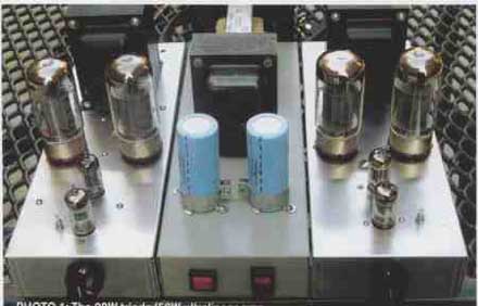
Important: The two amps and power supply are constructed on three 13 x 5 x 2” aluminum boxes (Photo 1). This simplifies the wiring and layout because the power supply and amps have a unique construction process. Do not use steel boxes, because grounds require stripping the painted steel boxes to bare metal. Also, drilling and punching holes are much more difficult with a steel chassis. The front of the power amp chassis has a heater and high voltage on-off switch. The rear of the power supply chassis has two power connectors, power cord and fuse. The rear of the amp chassis has three speaker terminals and an RCA connector. I recommend you use an 80-cfm fan, located directly behind the filament and plate transformer.
AUDIO SWITCH BOX
A commercial audio switching device is required to permit the two separate amps to function as integrated amps. You can purchase a $27.50 (Recoton) 4-position A/V selector switch from Parts Express or you can build your own switch using double pole, 6-position rotary switch PN 275-1836 from Radio Shack with appropriate box and RCA connectors. I used a commercial unit to avoid unnecessary work. I drilled two holes at the edges/center of the box, so I could mount the box to the side of my cabinet using wood screws.
FIRST STAGE AMP
The first stage amp (Fig. 1) is a paralleled 12AT7 with a flat frequency response of 20Hz to 18kHz and a distortion of 0.7% with a 5V RMS output. The plate impedance is 5kOhm and the paralleled sections have a voltage gain of 36. The 5V output is the value required for full power output from the amp. The DC supply is +318V DC, and 80V DC is provided to the plate via a 47kOhm resistor. The cathode voltage is 0.8V DC.
An input signal of 0.4V AC (triode connected output stage) and 0.48V AC (UL-connected output stage) is required to obtain circa SV AC output from the first stage amp and a maximum output from the power amp.
Note: When making the stage gain and distortion measurements of the first stage and inverter stage, loop feedback is not applied.
PHASE INVERTER
The phase inverter is a 5687 long-tail inverter with a flat frequency response of 20Hz to 20kHz. It uses a 33kOhm plate resistor on the grid-driven side and a 47kOhm plate resistor on the cathode-driven side to obtain equal output voltages from the inverter. The cathodes have a resistor of 8.2kOhm and operate at 87V DC. The DC supply is +472V DC.
The plate voltage via the 33K plate load resistor is +268V DC, and plate voltage via the 47k load resistor is 250V DC. The plate impedance at these operating parameters is 4k-ohm. The input signal to the inverter is 5.0V RMS to obtain 36V RMS at the 6550 grids.
Inverter stage distortion is 0.5% (grid driven side) and 0.85% (cathode-driven side) at an output signal of 36V AC.
Note: I recommend you connect the amp in either triode or UL mode and leave it in that mode. It has been my experience that listening establishes a preference.
28W TRIODE POWER OUTPUT STAGE
The power amp stage includes 6550s connected in a push-pull triode con figuration. The 6550 output stage requires 36V RMS signal drive for the grids of 6550s to obtain a 28W output. The 6550s employ isolation resistors on the grid and screen to ensure the tubes are free of unwanted signals. The screen grid is connected to the plate via a 220-ohm, 2W metal oxide resistor for triode operation. A 470 ohm 10W resistor is connected to each 6550 cathode to provide a +50V DC bias voltage. The Ebb is +475V DC and the Eb (plate to cathode) is 430V and plate current information.
Operating at this level, the sonics of the sound are greatly improved; this is commonly referred to as the “sweet spot” and occurs circa the design center maximum level, and no color of the plates is observed. The distortion of the amp without feedback is 1.6% at lkHz-28W. With 12dB of loop negative feedback at 1kHz, the distortion at 28W is 0.5%.
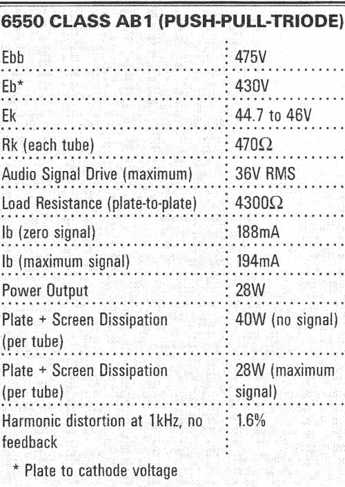
TABLE 1: TRIODE TUBE DATA
The damping is excellent, as 2.8V AC at the 8 secondary increases to only 3.1V AC when the 8-ohm load is removed.
The negative feedback loop of the 8 ohm secondary winding uses an 8.2k-ohm resistor, and the 4-ohm tap uses a 3.9k-ohm resistor. For proper operation of the feedback loop, select the 4 or 8-ohm secondary outputs.
Comment: The triode power amp shows no sign of ringing with a 10kHz square wave when a 0.1uF capacitor is placed across the secondary winding of the output transformer.
Caution: Before applying power to the amp, make certain the 100K grid resistors are connected between the 6550s grids and ground. This precaution will prevent catastrophic failure of the 6550s output tubes.
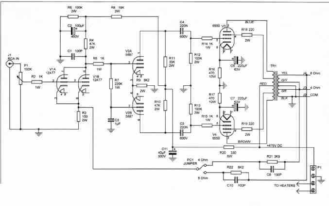
FIGURE 1: Amp Circuit. DC. See Table 1 (above) for plate dissipation
50W ULTRALINEAR POWER OUTPUT STAGE
The power amp stage includes 6550s connected in a push-pull UL configuration. The 6550 output stage requires 36V RMS signal drive to obtain a 50W output. As in the triode mode, the 6550s employ isolation resistors on the grid and screen to ensure the tubes are free of unwanted signals. The screen grid is connected to the UL winding via a 220-ohm 2W metal oxide resistor for UL operation. A 470 low resistor is connected to each 6550 cathode to provide a +45V DC bias voltage. Also as in the triode mode, the Ebb is +475 V DC and the Eb (plate to cathode) is 430V DC. See Table 2 for plate dissipation and plate current information.
The distortion of the amp without feedback is 3% at 1-kHz-50W. With 12dB of loop negative feedback at 1kHz, the distortion at 50W is 0.8%. The damping is excellent, be cause the measured 2.8V AC at the 8-ohm secondary increases only to 3.2V AC when you remove the 8-ohm load.
As in the triode mode, the negative feedback loop of the 8-ohm secondary winding uses an 8.2k-ohm resistor and the 4-ohm tap uses a 3.9k-ohm resistor. For proper operation of the feedback loop, select the 4 or 8-ohm secondary outputs.
Like the triode amp, the UL amp is free of ringing at 10kHz when a 0.1uF capacitor is placed across the 8-ohm secondary. And the same caution before applying power to the triode amp also applies to the UL amp.
OUTPUT TRANSFORMER
The 1650N-output transformer is rated for an output of 60W. The transformer has a 40% tap on the secondary winding to permit UL operation. The transformer provides excellent fidelity and required a well-thought-out design to operate over a frequency range of 30Hz to 20kHz. To obtain this frequency range from a ($79) transformer (weight 6.8 lbs) with such a large amount of iron and large circumference coil is indeed commendable. This transformer also measured well in square wave testing.
Comment: My philosophy is to design affordable hi-fi equipment for the audiophile, and Hammond transformers met that requirement.
POWER SUPPLY
The power supply contains the power transformer, heater transformer, capacitors/resistors, switches, and a low noise 80cfm blower fan (cools the power transformer and output tubes). The front of the chassis has separate heater and high voltage switches to permit applying heater power prior to applying high voltage. The rear of the chassis has a power connector, power cord, and fuse. The power supply provides power for two push-pull power amps described in this article. The 80cfm fan is located directly behind the filament and power transformer.
TABLE 2: UL TUBE DATA
The power supply (Fig. 2) has a 6.3V AC center-tapped 10A heater transformer and a 200V AC 870mA plate transformer. The plate supply has a full-wave bridge with two 560 capacitors functioning as a voltage doubler circuit. In a voltage doubler application, the current rating of the transformer is reduced to 435mA. The final filtering of the +475V DC is provided by two 560 capacitors connected in series with a 51K-ohm resistor connected across each capacitor. The series-connected 51k resistors function as a bleeder.
The AC ripple of the +475V DC output of the power supply is 3.9V AC. The ripple at the 40uF capacitor of the inverter is 1.6V AC and 0.2V AC at the 100 capacitor of the driver. The plate and heater transformer furnishes power to R and L channel power amps. The 12AT7 and 5687 heaters are paralleled for 6.3V AC operation.
Important: To prevent electrolytic capacitor burnout, separate switches are provided for the filament and high voltage circuits. The high voltage switch is connected to the output side of the heater switch so it can never be turned on unless the heater switch is set to the on position.
The triode amplifier frequency response at 28W is flat from 30Hz to 20kHz (Table 3). The 1kHz and 10kHz square waves at 28W are reproduced perfectly and the 100Hz square wave shows a moderate amount of tilt. Sensitivity is 0.4V RMS for 28W output and 0.24V RMS for low output.
The UL amp frequency response at 50W is flat from 30Hz to 18kHz. The 1kHz and 10kHz square waves at 50W are reproduced perfectly, and the 100Hz square wave shows a moderate amount of tilt. Sensitivity is 0.48V RMS for 50W output and 0.22V RMS for low output.
Caution: If the amp squeals when it is first turned on, reverse the plate leads or the 5687 output coupling capacitors. Use an inexpensive speaker during the initial turn-on.
FORCED-AIR COOLING
Photo 2 shows an 81cfm (noise 33dB) fan located directly behind the filament and power transformer. The fan also cools the four 6550s. Use mounting feet on the bottom of the chassis to give good under-chassis airflow.
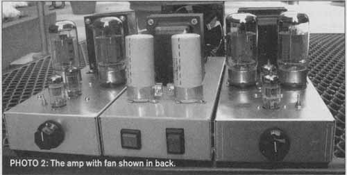
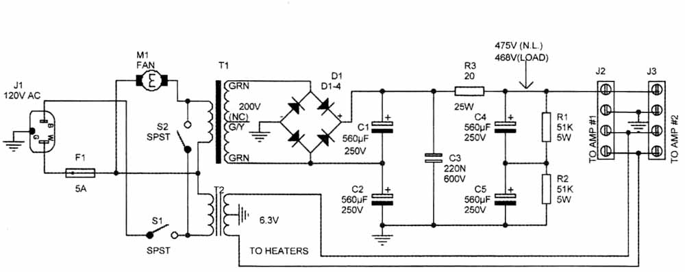
FIGURE 2: Power supply.
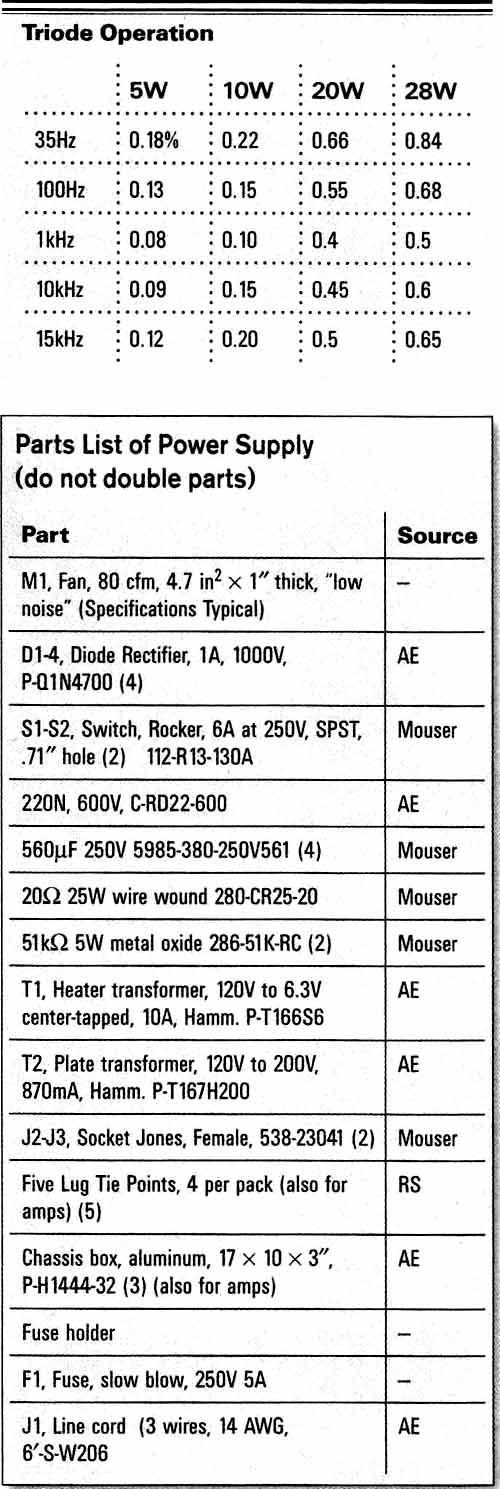
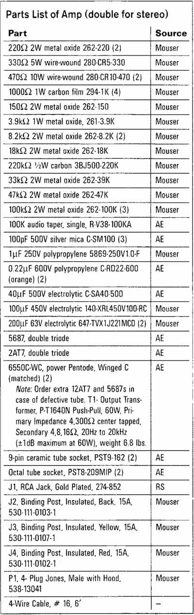
TABLE 3: TRIODE POWER AMP DISTORTION WITH 12DB FEEDBACK; Parts List of Amp (double
for stereo)
CONSTRUCTION TIPS
Use an aluminum chassis and not a painted steel chassis to ensure good grounds and ease of hole punching. Do not use a common ground bus. Use single ground lugs and the ground lug of the five-position terminal strips for all grounds. All audio signal leads over 3” must use a shielded lead grounded at the input end. A short ground path is provided for the plate, grid, and cathode circuits.
Use a shielded cable (although not required) for the inverse feedback lead. Use 16 AWG hook-up wire for the R and L channel heaters of the amp. Mount the 6550 tube sockets so the centers of the socket are about 3” apart. The four- conductor cable has wires from one end connected to the B+, chassis ground, and heaters of the amp and the wires from the other end connected to 4-pin, male Jones plug, P1.
WARNING: Lethal voltages are present! Exercise extreme caution when constructing and testing the amp. Never leave the amp upside down when children are present.
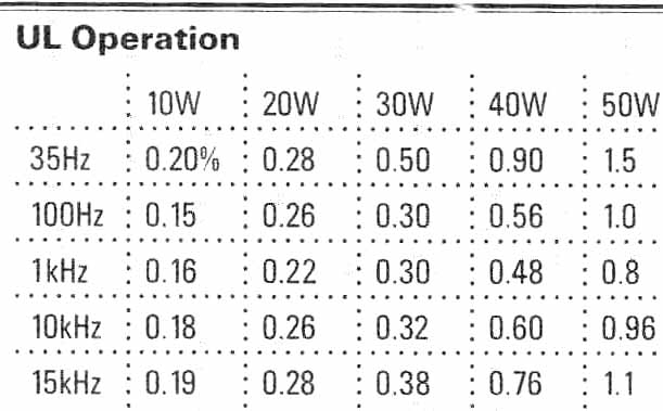
TABLE 4: UL POWER AMP DISTORTION WITH 12DB FEEDBACK
[the discussion above is adapted from an article outlined in audioXpress Jan. 2007]