|
|
.Here’s an amp project especially for first-time builders featuring the 6BQ5 tube.
In order for this beloved hobby of ours to thrive and survive well into the future, we must always strive to make it interesting to newcomers. These new hobbyists should be encouraged to explore the art of building their own equipment. This can be accomplished by providing them with simple, easy-to-build projects that will work as specified and will also give them the pleasure of knowing that they can complete it and proudly say that they built it themselves. These projects should be inexpensive to construct, should work from the very first time they are turned on, and also please the builder with their sound.
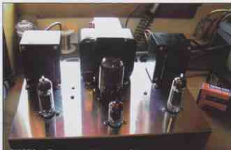
above: Photo 1 -- one possible exterior design!
BABY BOTTLE KING
A colleague, who has contributed many of his great ideas, recently mentioned a lack of articles regarding what I consider to be the king of the “baby bottles,” the 6BQ5/EL84 power tube. I have built some push-pull amps using this wonderful, hard-working little tube, but even though they were fairly simple in construction and low in parts count, I wanted to build one for first-time builders, and one that would sound really good.
The 6BQ5 sounds great in push-pull, but what would it sound like in single-ended triode mode? I had a few of these tubes in stock in my hobby room, so I dug out the parts I would need. I ordered a chassis from Antique Electronics Supply (tubesandmore.com) and found that the Hammond #H1444 was the perfect size at 12” x 8” x 2”. It held all of the components and has a nice open look, giving the tubes good spacing for keeping things cool (Photo 1). I had some Hammond output transformers handy, #1645, and the load of the primaries on these transformers gave me the necessary load for the 6BQ5s into my 8-ohm speakers. I used the #BR-1 speakers from Parts Express, which, although not super high efficiency, sound really good with this amp.
I realize that PP transformers are not quite suited for single-ended circuits, because the SE units have an air gap in the core to keep it from saturating with DC. Using the push-pull Hammonds will cause a slight rolloff below about 50Hz, but that is close to the limits of the speakers I am using, so it does not cause any problems. Later in this article I will explain how to keep the DC from the primary windings for those of you who want a flatter frequency response.
I didn’t use it because, as usual, the engineers at Hammond are a bit conservative with their ratings, much as they were with the #125CSE transformers that I used in my “Mini Single-Ended Amp” project.
I could not detect much of a rolloff in the low end while listening to music, which, for me, is where it counts. Funny how the ears and the meters don’t always agree, huh? You may use any output transformer that has the required load for the 6BQ5s, but the Hammond #125 series is a good and inexpensive choice to consider. Also, the wiring hookup for them is very easy.
I built two versions of the amp and I used tube rectification for the power supply in one and diodes in the other. You may use whichever you prefer. Just remember to use the correct type of input, a choke-capacitor input, so that, when used with the listed power transformer, your B+ won’t be too high.
POWER SUPPLY
I used the 5V4 type of rectifier tube for the B+ in the amp because it was in my stock, will handle the load, and offers the time delay that I think is necessary, which keeps the high voltage from hitting the plates of the tubes before the cathodes warm up. Much discussion has taken place about the benefits of the timed delay of B+, so I won’t go into it again here. Let me just say that I want to protect my NOS tubes as much as possible! If you use diodes for your power supply and you want the time delay, just use the octal (V1) socket for a delay relay #T-6C45-DR from AES. I used a timed relay that was in my stock. It has a certain “industrial” look to it, but it works very well.
If you already have separate transformers for the heaters (6.3V) and the high voltage (B+) that you can use for this project, you can wire in another switch to turn on the B+ after the heaters have warmed up for 30 to 45 seconds. There will be room under the chassis for most of the small transformers that are available from AES. Any one rated for 6.3V at 4A will do just fine. You can also wire in a switch and relay to turn on the B+ when using only one power trans former for the amp. In case you do use this switch and relay setup, then you can omit the octal socket altogether. Some of my other equipment has this switched type of “on-standby” and “operate” capability, which works well.
When using a timed relay or a switched relay to turn the B+ on, try using a 2W 100k resistor and a 100nF x 630V capacitor across the contacts to prevent the “thump” that you can hear in your speakers when the HV is sent to the tubes. The power transformer used here is from Hammond and provides all of the voltages needed in this amp without overloading. The part number is #T272HX. You will note that the measurements for all of the sockets and transformers’ mountings are on the drawing for the layout of the components (Figs. 3 and 4).
Following the wiring diagram on the schematic (Fig. 1), you should have no problem with mis-wired connections. The 5V leads from the 272HX go to the filaments of the 5V4, pins #2 and #8, and the high voltage leads are connected to pins #6 and #4. Be sure to connect the B+ supply wire to the correct pin, #8.
The center tap of the transformer is connected to ground, which is where I placed the B+ protection fuse. Some surprises in life are fun, but a short in your B+ circuit is not one of them! This will prevent burning out a perfectly good power transformer and will save you the headache of having to buy another one. Remember, transformers are not usually returnable to the dealers when the windings are burned out, and, yes, they can always tell!
The type of filter used in the B+ circuit is of the choke input configuration. It places the choke in the wiring before the capacitor. I used two chokes in the power supply—one for the B+ to the outputs and another for the B+ to the input stage. There was room under the chassis and the chokes I had were correct for the loads without being pushed out of their range. You may use one larger choke if you wish, but you may need to adjust the voltages to the circuits.
Using these chokes makes it easier to obtain the required voltages for the amplifier circuits, and they fit under the chassis quite well. The resistances of the chokes and the other resistors keep matters in check. The 120V supply circuit is also fused for extra protection, a procedure that you should always do. The fuse ratings are in the parts list.
The heater circuit is straightforward in that it contains only a full-wave bridge rectifier and filter capacitor. Depending on your power mains line voltage at your home, you may need to adjust the capacitance to keep the heaters at around 6.3V DC (±10%).
Increase or decrease the capacitance accordingly. I used some standard electrolytic capacitors for the B+ filtering (47pF x 450V), which seemed to filter the B+ quite nicely. Be sure to observe polarity with these caps! I normally use bypass capacitors in the HV, and you may use them if you prefer to “tailor” the B+ to your liking. A 330nF x 630V DC usually does the trick. The hum and noise in the amp is minimal, and you can only hear it when you place an ear close to the speakers.
If you decide to use diodes for your B+, then use the optional power supply diagram included with the schematic (Fig. 1). Use good-quality diodes. Both the standard 1N4005 and the high- quality Hexfred diodes are available from AES. When using diodes, you can add some extra filter capacitors to help smooth out your B+, which you can’t always do when using rectifier tubes. I built two of these amps using both types of power supplies, and I can’t really find much difference in the sound.
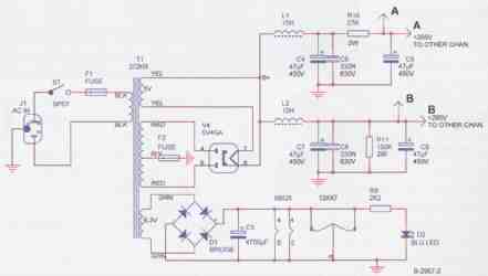
FIGURE 1: Vacuum tube power supply diagram.
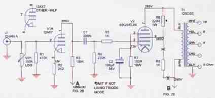
FIGURE 1A: Amplifier circuit.
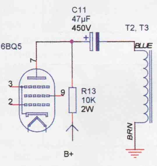
FIGURE 1B: DC blocking option if using push-pull transformers (Omit if using
Hammond #125CSE.)
THE TUBES
I used a 6AX7 for the first stage of amplification. If you think that this is the same as a 12AX7, you are correct. The only difference is the heater voltage. I could have used the 12AX7 here, but I decided on some great NOS Tung Sol 6AX7s that I wasn’t using.
I can’t say enough about the Tung Sol tubes. I used their 6550s in my single-ended project, and they remain my favorite brand. I realize that most of them are not available anymore, or are too costly, so I am listing other brands for this amp. There are many good 12AX7s available today to choose from. Just remember to wire the 12AX7 for the proper heater voltage.
You will note that each of the triode sections is dedicated to an individual channel. You may use either section for whichever channel you decide, or you may follow the pinout on the diagram (Fig. 1A). Take note: Following the diagram on any first-time project is very important! It will prevent mistakes that could possibly be costly and slow down the completion of your project!
The 6AX7 (12AX7) tube makes it easy to drive the amp to its full power. Using the circuit as shown with an input of around 0.1V drives the amp to a comfortable listening level when you use speakers that have an efficiency of around 90dB. And when you increase the input to around 0.5V, the amp is driven pretty hard and the distortion be comes evident. So, if you choose to use the amp in a direct-connect setup with your tuner or CD player, you will need some sort of volume control to prevent it from being overdriven.
In case you are not going to be using this amp with a preamp or other source with a volume control, then install the one shown on the diagram. If you want less gain on the input stage, you can experiment with a 12AU7 or a 12AT7. I’m using mine with a Dynaco CDV-1 tubed CD player with its own volume control.
The 6BQ5s—the power output tubes—are still easy to obtain, with many different brands to choose from. They deliver about 2W in triode mode, or, about 5W in pentode mode. These tubes are very rugged. Many guitar players still use practice amps that have them in either SE or PP configuration. Personally, I have never replaced a 6BQ5/ EL84 due to failure; some have become a little soft sounding as they aged, but, hey, that’s normal.
The tube uses cathode bias, which makes the circuit simple and allows you to try different tubes without needing to worry about any adjustments. I tried some JJs from AES that have a lot of mid- bass punch and a good bottom end. I also used some NOS Sylvanias which have a fantastic clarity about them. The midrange from the Sylvanias is great, and the tubes seem to cause the little amp to take on a personality of its own. I thought my “Mini Single-Ended Amp” sounded good, but, wow, the 6BQ5s are right at home running in SE triode mode!
Just how long can some tubes last? Well, just for the record I looked it up. It seems that there was a “Klystron” tube used in a radar installation once which accumulated about 240,000 hours on it. That’s about 27 and a half years! I have pulled some tubes out of old console radios from the 1930s that still tested good.
After about a ten-hour break-in, the amplifier took on a certain “sparkle” to its sound, one that was very easy to get used to. The sound was effortless in its delivery and very easy on the ears, with no fatigue after a long listening session. I think I’m hooked.
CHASSIS LAYOUT AND CONSTRUCTION
The Hammond chassis box has plenty of room for all of the parts you will use to complete your amplifier. You will need a couple of hole punches for the tube sockets. The sizes are 0.75” and 1.125”, or, in layman’s terms, ¾” and 1 1/8”. Or, you can have your local electrical shop punch out the pre-marked chassis holes with the Greenlee brand of punches that will do the job very neatly and quickly. Some hobbyists use a proper-size drill or metal nibbling tool such as the #ST806 that AES carries. Whatever works for you is OK.
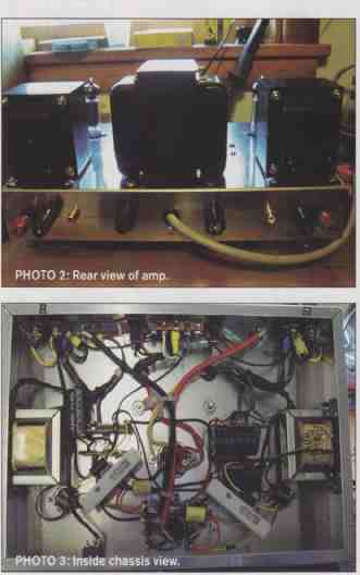
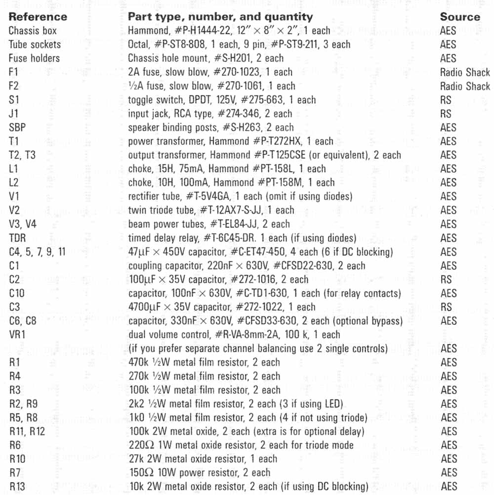
When working with the chassis, be sure to remove all of the shavings and burrs that are left over from drilling and punching the metal. The spacing and hole sizes for the transformers and the placement distances are on the chassis drawing (Fig. 3). The mounting holes on your output transformers will vary, de pending on which one you decide to use. Using this drawing will help take the guesswork out of where to put things on your chassis. Actually, you may arrange your amp however you wish, but I found the layout here works very well. You can see some good views of the amp layout in Photos 1, 2, and 6. I put the power switch on the right side because I’m right-handed.
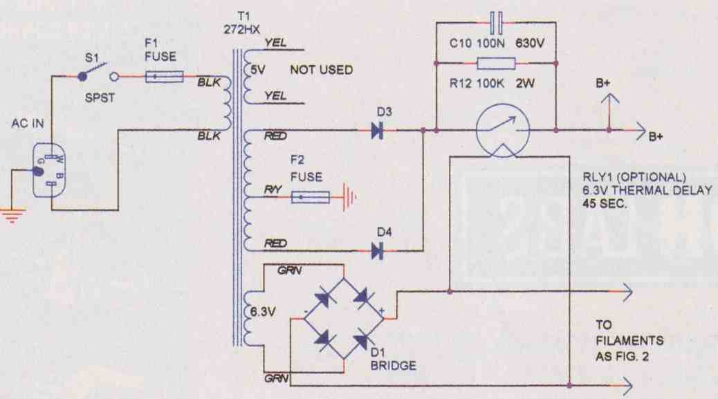
FIGURE 2: Solid-state power supply diagram.
I installed the blue LED on the left side. The glow of the tubes is usually enough to let you know that the amp is on, but I really like the little blue light on the front of the chassis. It’s easy to tell the amp’s status at first glance from across the room. This LED is very bright when used with the 6.3V DC supply in the circuit, so I used a resistor to reduce the brightness level. The resistor is 2.2k ½W and keeps the LED from being brighter than the glow of the tubes, which most audio hobbyists seem to enjoy.
I used #6 hardware for all of the mounting of the chassis top parts except for the transformers. I used #10 for them. The types of terminal strips in Photo 3 are very handy for mounting all of your components and are avail able from AES or your local electronics store. You may use as many as you need to complete your chassis wiring hook ups. You can mount them wherever you consider to be a good tie-in point for your wires and parts. The socket mounting hardware is always a good place for them because you will terminate almost everything into the tube socket connections. Try to route the wires carrying the AC power (120V) from your supply line away from your low-level signal wiring to reduce the possibility of any induced hum. Be sure to use rubber grommets on the holes that wiring will pass through on the top of the chassis and on the power wire hole in the back plate.
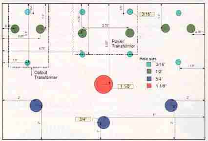
FIGURE 3: Chassis layout—top plate.
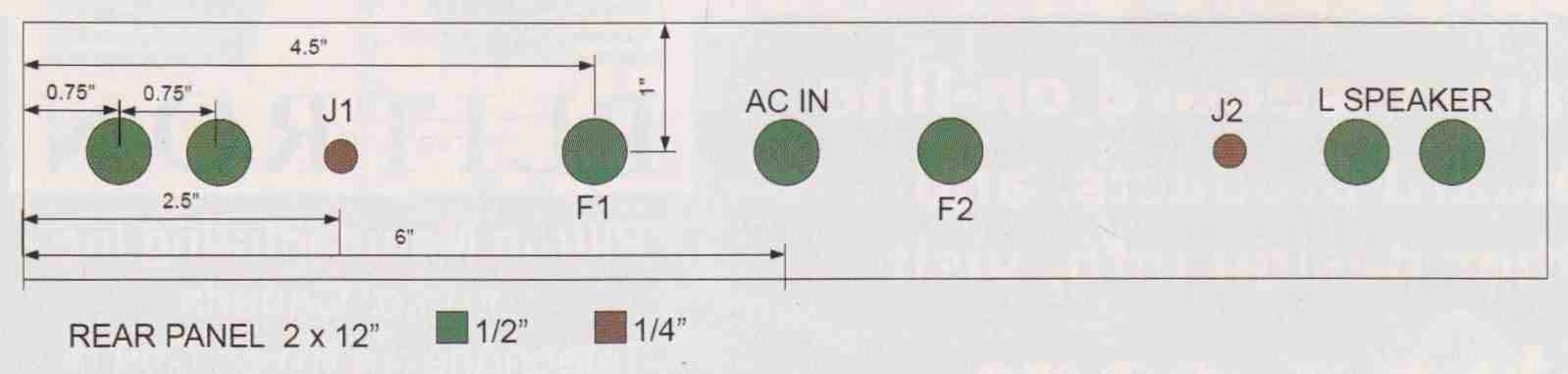
FIGURE 4: Rear panel.
To make it easier to move the chassis around while doing the wiring, you might want to mount the transformers last after you are through with most of your hookups. This also makes it safer because the chassis is much lighter to handle. For the version with the diode type power supply, I painted the chassis (Photo 6) when I finished mounting everything. You can paint yours any color you like or leave it as is with the shiny aluminum surface, as I did for the version with the 5V4 tube rectifier power supply. Again, fellow hobbyist, have it your own way.
THE AMP CIRCUIT
The circuit used in this amp is very simple and easy to wire if you follow the diagram (Fig. 1A). You can include the volume control indicated on the diagram, and connected directly to the grid of the first tube, or omit it. The wiring for each channel is identical, and the easiest way to prevent mistakes is to wire a component, resistor, and so on, into one channel first, then repeat the process on the other side. Try to use heat-shrink tubing on the exposed component leads where possible. This will make your circuits much safer to test and will prevent any short circuits where you don’t want them to happen.
After installing the part, look at the other channel to see whether they match and then compare both to the schematic diagram. Repeat this as many times as necessary until you are sure that all looks well. Photo 3 includes a view of the inside of the chassis. The hookup of the output transformer is shown on the diagram according to the color codes for the Hammond #125CSE.
Depending on the type of transformer you use, be sure to follow the color codes indicated on the diagram that comes with your transformer. If you use the Hammond #125CSE, you will have fewer wires on the primary side. The #1645 has a center tap and two UL taps. I just isolated them, covering them with heat-shrink tubing, and secured them under the chassis. Depending on the resistance of your speakers, you will need to wire the secondary according to your diagram.
If you prefer to experiment with the hookups for the transformer, just remember to isolate and insulate the unused wires. You can use the extra circuit in Fig. 1 B if you want to block the DC from the core of your amp’s output transformer, but if you use a Hammond #125CSE you won’t need it. Larry Lisle, whose work I have always admired, demonstrated this method in an article back in 1996 in Popular Electronics, where he showed how to construct an all-triode SE amp. I’ve never used the circuit, but if Larry says it works, that is good enough for me. If you don’t already have some PP transformers on hand, then just order the 125CSEs and you can avoid the extra circuit.
One of the advantages of a single- ended amp is the low parts count, which means simplicity. Because it is single- ended, there is no need to use a phase inverter. I am not even using any feed back in the circuit. By using cathode bias for the output tube, you don’t need to worry about a separate power supply for the bias. This is accomplished with the use of the resistor and capacitor on the cathode of the 6BQ5 to ground. I experimented with different values of capacitors for the bias and settled on the one on the diagram after extensive listening tests; again, tuning by the ear, not the meter.
By the way, I used “star” grounding and tied all of the grounds into a central point near the right channel input. With around 285V on the plate, I was looking for about 7.5V at pin #3 on the 6BQ5. I ended up with almost exactly that reading. I used 25W resistors for the bias because I had them handy. You can use a 10W for this tube because the heat output is well within that range. The 25W run really cool.
In Photo 3 the amp is still under construction, and yet it should give you a basic idea regarding the placement of parts, but you can arrange yours in any way you wish. In order to use the 6BQ5 in triode, you must connect the plate, pin #7, to pin #9, as shown in Fig. 1A using a 220 ohm 1W resistor. If you don’t want to use triode mode but want more power, then connect pin #9 directly to the B+ going to the output transformer using a 1kO resistor. This option is shown on the schematic diagram including the extra resistors. Personally, I like the triode mode better.
You may use any brand of resistors and capacitors to wire your amp, and, if it is your first project, you don’t need to go for the “high end” parts. The parts listed have given me a really good sound and their costs are minimal. That is another one of the joys of this hobby: You can spend as much or as little as you like on your amp, you can modify it at any time in the future if you wish, and, if it ever needs it, even repair it yourself. The operating parameters for the amp are indicated on the diagram and can be easily measured with a standard volt-ohmmeter, either analog or digital. More about this in the testing section.
above: Photos 2-5
TESTING YOUR AMP
Before you start testing the circuits for proper voltage readings, you must re member that you have some high voltage under that chassis, both the mains power and the B+! The 6.3V and the 5V supplies will forgive most mistakes; the 120V AC and the B+ will forgive none! If you are not used to measuring these types of voltages, you should do everything possible to ensure that you will have a safe and satisfying experience learning how.
If you don’t have a test meter, these are available from AES or from your local electronics store. Read the instructions that come with your meter and practice measuring with it on some low power circuits such as batteries, resistors, and so on, until you feel comfortable with its operation. Remember, your eyes can only see the components of your amp, the meter will tell what is actually going on inside of the circuits.
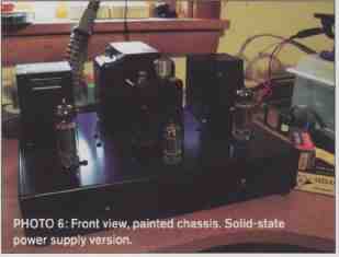
In Photo 5 you will see a standard test lead probe that has been made much safer. I slipped some pieces of heat-shrink tubing over the shaft and shrank them with a heat source, leaving only a small portion of the tip bare at the end. This tubing is rated for 600V and will keep you from shorting the probe to ground or other connections while touching the test points on the circuit. This will keep you and your amp much happier.
Because all of the readings are made with reference to ground, use a clip to secure the black negative (-) probe to the chassis ground so that you don’t need to hold it with your other hand. This way you won’t lose that sparkle you have in your smile when nearly 300V of power passes through your body! Touch each test point with your red positive (+) test lead while holding it with one hand only. Many experienced hobbyists will put the other hand in their pocket while testing—a wise move.
Note the reading and write it down if you wish. Your readings will be within about 5% of the readings on the diagram, depending on your power source. Leave the fuse out of the B+ fuse holder when reading the low voltage points. Again, safer!
The 6.3 and 5V sources may appear a little high without the load of the tubes on them. This is normal. After you are sure that you have the correct voltages for the filament and heater supplies, unplug the amp and install the tubes. Push them into their sockets carefully, without forcing them.
Put the B + fuse back into its holder and connect your speakers to the proper terminals, observing the polarity. Plug the amp back in and turn it on. Watch for the soft glow of the heaters on the 6AX7 (12AX7) and the 6BQ5s and the glow of the filament on the 5V4 (unless you used the diodes for your power supply).
You may hear some hum coming from your speakers as the amp warms up. When you touch the input jack center lead, that hum will become louder. This is normal. If you don’t want to hear the pops and hum produced while testing, simply short the center of the input jack to ground. This type of short is acceptable. After the amp warms up, take your readings of the circuits again. Remember, now the B+ is flowing!
Your heater, filament, and B+ readings should all be close to normal. Sometimes in my area the utility power voltage will go as high as 125V and the B+ in my amp will hit around 300V. This doesn’t really cause any problems because the tubes are rated for 300V. They will be come slightly warmer and I notice a little increase in the volume, but that is not serious. If you notice that a bad solder joint is making a problem, turn the amp off, unplug it, and wait for the capacitors to discharge.
Note: The B+ capacitors are discharged by the load of the 100k resistor R11. The filter capacitor for the heaters is discharged by the constant load of the heaters. Resolder the joint. If the joint is on a tube socket, remove the tube before applying heat to the socket terminal! After you are certain that everything is OK with your amp, you are ready to hook it up to your preamp and/or a music source. I used some stick-on rubber feet to give the amp some air circulation under the chassis. This is always a good idea.
HOW DOES IT SOUND?
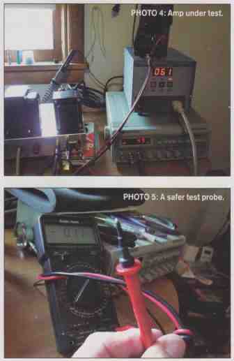
At first I did some frequency response tests from the amp (Photo 4), but that is never close to the dynamics of real music. I played a track from Toni Braxton, Spanish Guitar,” and noticed how the sounds of the strings—actually each individual string—of the instrument seem to come forward from the speakers until I felt as though I could reach out and touch them. I played a variety of music from classical to soft rock, to country, and some oldies but goodies, and I started to hear things that I hadn’t noticed on other amps, especially solid-state.
I built a 25W per channel SS amp, and I swear it is as though it places a veil over the midrange and upper midrange. I have modified it to the hilt, but it just won’t sound natural. This little triode amp makes it sound as though the music coming from its silicon parts is smothered under a mattress. Voices from this triode amp take on a new life, even at low volume settings. The voices of Hayley Westenra and Enya are almost unreal. The soft violins on “Clair De Lune” and Martha Babcock’s cello on “The Swan” from Boston Pops with John Williams almost brought a tear to my eye. Piano music seems very natural.
So, I wonder, how can this simple, inexpensive amp stand on its own with some of my other equipment? There are very few parts in the signal path, and the triode sound is virtually unmatched in audio amps. I listened to a 300B amp once, and, let me tell you, that will spoil your ears real fast. I realize that this amp is not a “true triode” amp, because I’m using a pentode that is strapped into triode configuration, but I think that the little 6BQS/EL84 is happy running in triode mode.
I also didn’t use any feedback in the circuit, because I believe that feedback would actually take away from the SE triode experience. Feel free to experiment with it if you desire. Mine sounds fantastic just the way it is. Now I have a whole new tube amp to listen to in my hobby room.
By the way, the amp draws 61W at idle and around 64W at full power, so it is very easy on the utility bill. Remember to give your amp a few hours to settle in, and you will start to notice the warm yet lively sound it can produce.
If you are a first-time builder, remember to take your time as you go through this project. Don’t rush. To hurry can only produce mistakes, while taking your time will cause you to absorb the reason and purpose of your endeavor. This way you will learn and understand more about vacuum tube circuits. If you desire to learn even more about the “why” and “how” of tube equipment, obtain some of the books available from Amazon, etc.
The tubes and other parts listed for this amp are low in cost yet will give you a finished product that will be well worth your effort. I’m sure that there are others who will want to modify and improve on this amp’s design, but I am going to leave mine as is, sounding great!
I hope that your version of this amp pleases you with its sound. I also hope you find the same joy in building your own equipment as many hobbyists. If you do decide to try this as a first-time project, let me be the first to welcome you to the Do-It-Yourself Audio Club.
PARTS LIST: Reference -- Part type, number, and quantity -- Source
Miscellaneous hookup wire, various sizes and colors, sufficient quantity for all circuits, local RS heat shrink tubing for bare component leads and test probe modification, stores shielded audio cable for input circuits, solder and so on.
[the discussion above is adapted from an article outlined in audioXpress Jan. 2007]