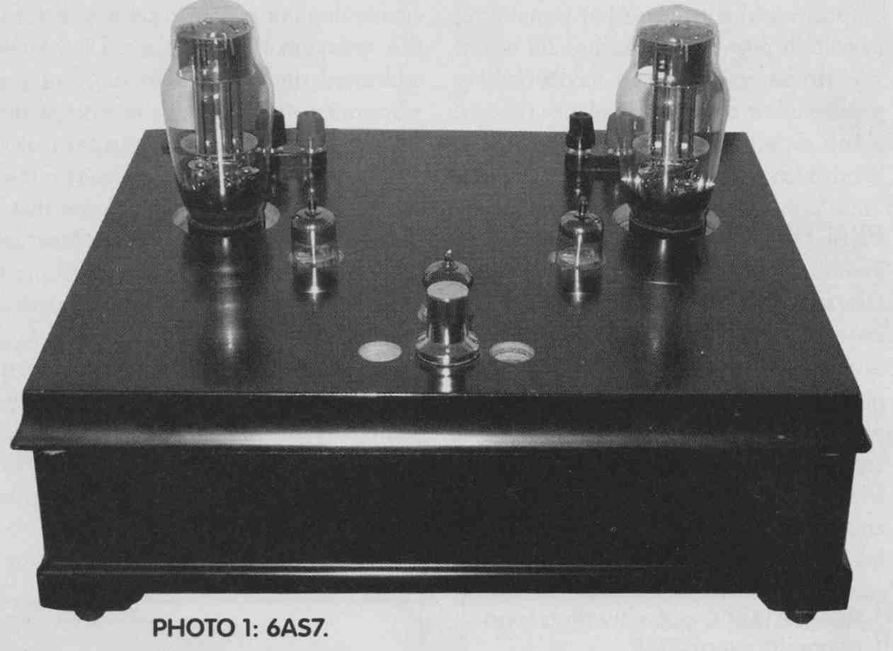
This amp design features the use of power toroids in the output stage.
This design was inspired by Steve Bench, who published an article on his website describing the application of low-cost toroidal power transformers as push-pull output transformers. Such a transformer has naturally low leakage inductance that is substantially independent of winding sectionalization; consequently, the shunt capacitance is also low.
The downside is that a toroidal transformer is easily saturated by DC current. I realized that I could minimize the DC unbalance by using a separate, care fully adjusted constant-current source in each output stage cathode, then AC- couple the cathodes to produce a long- tailed-pair (or differential pair) power stage. The obvious drive stage for this arrangement is also a differential pair:
The resulting combination of a balanced output stage driven by a differential pair is a “natural” development of Class A push-pull topology that addresses highly accurate push-pull signal current balance not only in the drive stage(s) but critically, also in the output stage resulting in mini mal signal current flowing in the power supply with a consequent lack of dependency on the quality of the power supply for excellent sonic performance.
Any push-pull amplifier that does not have an AC current-balanced output stage will modulate the power supply due to even a very minor mismatch in transconductance of the output tubes or in the loading reflected to each output tube. Similarly, single-ended amplifiers that do not use current source feed will modulate the power supply. These statements are reflected in discussions regarding how audible different rectifiers are; such observations clearly indicate that audible levels of signal current are flowing in the power supply, the least linear portion of the circuit!
I took full advantage of this AC current-balanced output stage by not only using a common supply for the drive and output stages, but also by omitting a bypass capacitor across the supply. Listening tests showed that the bypass capacitor was unnecessary. This design does use AC coupling between the drive and output stages; the next iteration will use DC coupling, resulting in a design with remarkably few capacitors.
PRINCIPLE OF THE DIFFERENTIAL PAIR AMPLIFIER
The balance of a differential pair amplifier is proportional to the “tail” impedance, with the tail being the common- cathode current source, often a resistance: The longer the tail the higher the impedance and the better the balance, hence the differential amplifier used to be known as a “Long Tailed Pair.” The earliest reference to this topology that I am aware of is from Alan Blumlein in UK patent specification 482,740 dated April, 1938 (Fig. 1).
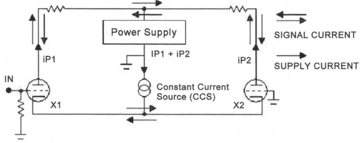
FIGURE 1: Differential amplifier supply and signal current paths.
The circuit works in this way:
If the grid of X is modulated, there will be a change in the cathode current of X1; since the sum of the currents flowing in X1 and X2 cannot change due to the constant-current source tail (CCS), the current flowing in X2 must change by exactly the opposite amount. Another way to look at this is if the tail impedance is infinite, there will be no signal current leakage into the tail; there fore, if the current in X1 goes down, the current in X2 must increase by exactly the same amount and vice versa.
Thus, if you have signal current balance, no signal current will flow in the power supply loop (from the coupled cathodes to the tail then back to the plates via the B+ supply) and thus the signal current flows in a loop through X1, via the cathode connection through X2 and via the plate loads back to Xl. The signal voltages developed at each plate depend on the plate load values, therefore, to achieve accurate voltage balance; the plate resistors (and any sub sequent loads such as grid leaks) must be accurately matched.
A CCS is, by definition, a device that has infinite impedance such that any change in voltage applied across it will cause no change in current flowing through it. Obviously, infinite impedance is not practical, but it is possible to construct a device that while exhibiting low DC resistance exhibits very high impedance. An example of this is a choke, which, however, does not ad dress the need for DC current balance in the push-pull output stage that is a requisite for this design. The next section describes a practical MOSFET-based CCS long-tail, suitable for a push-pull output stage.
APPLICATION OF A CCS TO A PUSH-PULL OUTPUT STAGE
The use of a CCS to accomplish extremely high tail impedance is now commonplace in balanced preamplifiers and drive stages. Since the advent of depletion mode power MOSFETs, it is practical to build a precision power CCS, suitable for use with an output stage. Unlike an enhancement mode MOSFET a depletion mode device can be source-biased (equivalent to cathode biasing a tube). This means that a bias voltage source such as a battery is not required, as would be the case with the enhancement mode device.
You can use such a device in the cathode return circuit of a push-pull output stage, resulting in what I have dubbed a “Power Long-Tailed-Pair” (PLTP). This circuit exhibits extremely accurately balanced signal currents in each phase, thereby minimizing any modulation of the power supply and thus the de pendency of the amplifier sonics on the quality of the power supply. In forcing the current draw to remain constant, the operation of this push-pull output stage may be properly characterized as true Class A.
DESIGN DETAILS
The input stage is a single-ended common-cathode triode, chosen to simplify the input interface. The alternative is a balanced input stage, capable of accepting a balanced or single-ended signal, but for this particular project I wished to keep the tube count down. The 6GM8 type chosen for Vi has a screen between the sections, making it suitable for dual-channel use.
I chose to omit a cathode bypass capacitor—the gain of the drive circuit is more than sufficient to permit full drive from a standard CD line source. In fact, the grid bias voltage for V1 is around 1V, so to avoid the possibility of overdriving the amp, there is an input attenuator VR1. The value of this can be what you choose—I had a 100k Alps Blue unit on hand.
I always put a safety resistor (R2) on volume controls to prevent disaster if the wiper should lift; this is a hangover from my youth when I could not afford decent parts. The 6GM8 (ECC86) is a low voltage type intended for application in instrumentation and car radios. This characteristic is useful here because the entire amplifier operates from a common 250V supply.
Because the first stage is DC-coupled to the drive stage, a low plate voltage on the first stage is helpful; in this design the plate voltage is around 21V at a plate current of 1.4mA. I have used this tube in a couple of phono stages as well as in this design and have found it to be excellent sounding. The B+ supply for the first stage is taken via RC decoupling (R5, C1) from the supply for the drive and output stages.
The input stage is DC-coupled to a long-tailed-pair, resulting in a Mullard type push-pull drive circuit. The drive stage (V2) uses an ES8CC (6922) in a long-tailed-pair configuration, the tail being a DN2540 depletion mode MOS FET CCS. To set the CCS, adjust a 250-ohm variable resistor for R6 until both plate voltages are between 150-155V (assuming the B+ is 250V), resulting in a total current for the pair of triodes around 13.4mA. Measure the pot and replace it with a good metal film resistor or simply leave it. The driven grid is DC-coupled from the input stage, while the undriven grid is DC referenced to the driven grid via an RC decoupling network (R8, C2). Because both the drive and the output stage are current balanced, I chose to experiment with omit ting the B+ decoupling (and consequent voltage reduction) between the output and drive stages. The sonic consequences of this experiment are described in the section Sound Of The Amplifier. Please note that the plate voltage exceeds the rating for the similar ECC88 and 6DJ8. The drive stage is AC-coupled to the output stage via C3 and C4 that terminate in the control grids of the output stage triodes; each grid is referenced to ground via resistors R13 and R14.
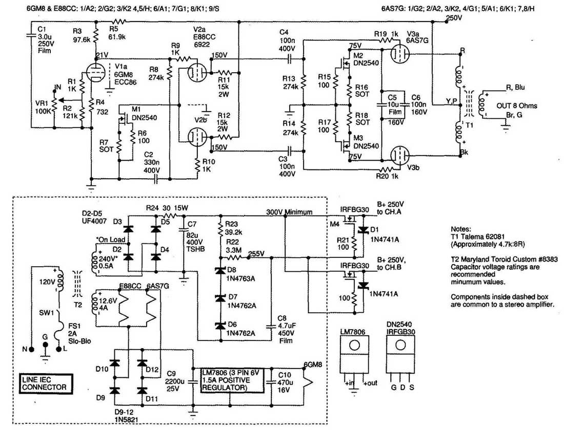
FIGURE 2: Low-cost 6AS7 PP.
Each output stage (V3) uses a single 6A57 double triode in Class A push-pull operating at a B+ voltage of 175V and 70mA per triode (140mA per push- pull pair). Following Steve Bench’s lead, I chose the Talema model 62081 50VA toroidal power transformer to serve as an output transformer. These devices have dual primary and secondary windings. With the secondary windings connected in parallel, the 62081 reflects approximately 4.7k to the series connected primary from an 8-ohm load, therefore 1.12k per phase—the plate resistance of a 6AS7 is approximately 280-ohm, so the 1.12k loading is suitable.
If the output triode pair is not perfectly matched, unbalanced DC current in the output transformer will result; because you are using toroidal transformers, you must minimize any unbalanced current, otherwise saturation at low frequencies may occur. One way to manage the unbalanced DC Current is to use a carefully adjusted CCS in the cathode circuit of each output triode. Thus, applying this current balance technique to facilitate using toroidal power transformers as output transformers is a logical implementation of the Power Long-Tailed-Pair concept described earlier; one that offers the possibility for an extremely good-sounding yet inexpensive amplifier design. I found that 1 could pair-match the current sources built using the DN2540 depletion mode MOSFET to better than 0.5mA easily, and possibly, as accurately as 0.1mA.
Setting up the CCS units is critical: If you have a good bench power supply, use it at 75V DC to power each CCS. Use an accurate Current meter in series with each CCS. Another way is to put a resistor in series with the CCS being set and monitor the voltage across it—say 47-ohm (1W minimum) x 0.07 = 3290mV. For a given current, the drain to source voltage for these devices varies: I suggest starting with 27-ohm (0.5W minimum) for R16 and R18, then adding parallel resistors until both sources are closely matched around 70mA each. The power dissipated by each DN2540 is almost 5W.
The signal current balance in the pair of DC current-matched output triode circuits is balanced by capacitor coupling the cathodes together, thereby producing a power-long-tailed-pair. Remember that the impedance of each CCS unit is extremely high, so the signal current “leakage” into the tail formed by coupling the two cathodes/CCS units together is also extremely small, such that the combination exhibits the accurate push-pull behavior of the long-tailed- pair, as I explained.
The value of the cathode coupling capacitor C5 merits some thought: At first glance, it appears that this capacitor need be quite large because the cathode resistance of a 6AS7 is around 90-ohm. However, the output transformer inductance combines with the capacitor to form a resonant circuit; with 10 the resulting response peak is around 5Hz. This L-C peak works to your advantage because it causes an LF response boost that extends upward into the frequency region where the reactance of the capacitor would otherwise interact with the cathode resistance to cause an LF rolloff.
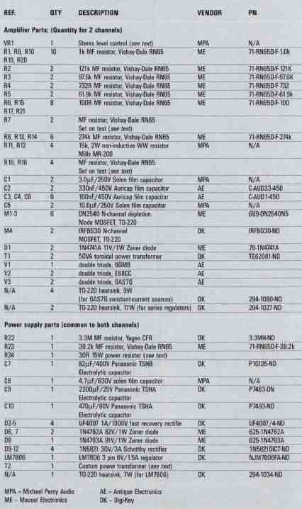
---PARTS LIST FOR 6AS7 CURRENT BALANCED PP AMPLIFIER. Amplifier Parts; (Quantity
for 2 channels); Power supply parts (common to both channels)
In fact, if the L-C peak were not damped by the plate resistance, the LF response would rise toward the peak, below which it would roll off sharply. In this case, the interaction of these parameters results in a nice smooth rolloff from —1dB at 23Hz to —3dB at 12Hz using just 10uF. If the plate resistance were higher, the damping would be greater, and a larger capacitor would be necessary to achieve the same performance. For example, with triode connected EL34s, the greater plate resistance increases the L-C damping so that for a similar LF response, the cathode coupling capacitor would need to be around 30uF. Thus, applying this current balance technique to facilitate using toroidal power transformers as output transformers is a logical implementation of the Power Long-Tailed- Pair concept described earlier; one that offers the possibility for an extremely good-sounding yet inexpensive amplifier design.
POWER SUPPLY
The B+ requirement is 250V at 155mA for each channel (total 310mA). This requirement plus an operating margin for the B+ source followers necessitates a transformer that can deliver 240V AC on-load at 0.5A into a bridge rectifier, or, alternatively, 120V AC on-load at 1A into a voltage doubler. (The additional current is to accommodate the reservoir capacitor repetitive charging current.) I had a power transformer custom-wound: Maryland Toroid part number 8383. I recommend that you use Duncan Munroe’s free power supply design software, PSUD2, to design a raw DC supply that differs from the specified design.
High-perveance triodes such as the 6AS7 are susceptible to cathode strip ping so the B÷ must be delayed. Because I wanted to avoid the use of a tube rectifier, I decided to use a source-follower series regulator that is configured to ramp the B+ up slowly through the simple expedient of providing a long time- constant on the gate reference voltage filter. The gate reference-voltage is developed by a current from R23 flowing through a chain of zener diodes D6-D8. Such diodes have quite wide tolerances and a temperature coefficient, so I buy plenty and simply swap them around until the B+ voltage settles at 250V. The reference voltage is filtered by R22 and C8, which combine to a time-constant of approximately 15.5 s.
The source follower has a significant additional benefit—ripple rejection of around 60dB—thereby avoiding the need for a choke. The input voltage to the source follower must be more than 300V DC; otherwise, ripple troughs will be present on the 250V rail. I specified 240V AC for the transformer to avoid ripple breakthrough at low line conditions. The line voltage at my home is around 122V; also the ventilation avail able with my construction is not ad equate so I included R24 to reduce the dissipation of the source-followers. R24 should be rated for 15W; I suggest a Caddock MP-930 type mounted on a heatsink. If your construction has free- air circulation around the heatsinks like mine, or your line voltage is lower than say 117V, you may be able to omit R24. To manage the source-follower dissipation a separate unit for each channel is advisable. The dissipation for each channel (assuming an input voltage of 320V DC) is almost 11W. The two source followers can share the reference voltage. I used the IRFBG30 type; almost any n-channel MOSFET rated at 500V or above will suffice.
For the heaters, I used a common 12.6V AC supply for the 6AS7s and the E88CCs—this winding should be rated for at least 4A. Each pair of 6AS7s and each pair of E8SCCs were connected in series for 12.6V. A bridge rectifier (comprised of Schottky diodes) from the 12.6V AC winding feeding an LM7806 forms a convenient DC heater supply for the 6GM8.
MEASURED PERFORMANCE
This amp was designed as a “thought experiment” in search of excellent sound at low cost, not to achieve impressive measured performance. These results are quite remarkable given that the output transformers cost $18 each!
• —3dB, 12Hz to 47kHz
• —1dB, 23Hz to 27kHz
• Power at 2% (1kHz), 4W
• Sensitivity for 4W, 0.33V RMS sine (0.46 Vpk)
(The bandwidth was found to be consistent, irrespective of power.)
SOUND OF THE AMPLIFIER
This amplifier has been heard on speakers ranging from my home-built two-ways, home-built line arrays to Phy dual-con centric KM30 SAG drivers on Phy specification open baffles. My evaluation partner was John Dahlman, who is a professional bassist and a fellow member of the DC DIY Audio group. Among other issues, John concurred that a B+ bypass capacitor was not necessary, thereby confirming the efficacy of the balanced output/drive stage combination. The sound is extraordinarily clear, detailed, and articulate; in particular, the authenticity of the bass is convincing.
This amplifier images superbly, not just with respect to the soundstage but also the individual instruments; the speakers “disappear” quite easily. Overall it leaves little if anything to be desired when compared with SE 45s, SE 50s, and even SE 71As. It simply gets out of the way of the music. Such excellent sound is especially notable given the low cost of the output transformers.
CONSTRUCTION
I built my unit as an integrated stereo amplifier using one each of the sections of V1 for each channel. Use tightly twisted pairs for the heater wiring (keep this wiring as far away from signal wiring as possible). Ensure that the reservoir capacitors (C7 and C9) are connected as directly to the rectifiers as possible. The AC wiring to the rectifiers should be twisted and as short as possible. C9 and C10 should be located within 2” of the LM7806.
Zener diodes have a thermal coefficient; keep D6-8 away from heat sources. Di is a protection diode and can be close to M4 and M5 without any problem.
Use a central star ground point at the input socket—the line ground should come straight to this location. A line fuse (2A, Slo-Blo) is essential for safety (please do not omit this).
It is essential to use gate stopper resistors: 100-ohm is sufficient. Each resistor should be soldered right on to the gate lead of each MOSFET.
MOSFETs are static sensitive: I have not found it necessary to use antistatic mats or wristbands with the devices specified. However, take care not to wear synthetic clothing; especially don’t wear socks on a carpet, otherwise you will be a static generator! If your house is especially dry, increasing the humidity might be a good idea.
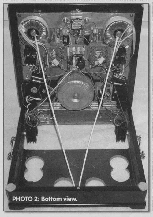
Take care to use generous sized heat-sinks for the output stage CCS units and the source followers, which are mounted either directly above or below ventilation holes in the chassis. I suggest a 9W heat- sink for each output stage CCS unit and a 17W heatsink for each source-follower; also a 7W heatsink for the LM7806. My construction—built in a pretty Bombay Company tea sampler box—leaves a lot to be desired. I ended up cutting out most of the base of the box and raising the top to leave a gap between it and the sides.
A neat way to build the six CCS units is to use the kits sold by K&K Audio. I generally use Radio Shack perfboard to construct source followers.
COMPONENTS
I used a 100k Alps Blue potentiometer for VR1. These units are available in motorized form with remote-control drive kits. Alternatively, given the exceptional sound of this amplifier, you may choose to use a 50k or 100k stepped attenuator; in this case, you may omit R2 with impunity.
I like the sound of Auricaps, which I recommend for the grid decoupling capacitor C2, the coupling capacitors C3, C4, and the cathode coupling bypass capacitor C6.
It is important to use a low-leakage cap for C8; otherwise, the source-follower voltage will not reach the intended value due to the resistance of R22 (3.3M). I used a Solen part here and also for the first stage B+ decoupling capacitor C1, and the output stage cathode coupling cap, C5.
The reservoir capacitor C7 can be electrolytic without degrading the sound of this design. However, a decent quality component such as a Panasonic TSHB is always worthwhile. I used UF4007 rectifier diodes, while a hexfred type (rated for 600PIV or greater) is also suitable.
As I built the design, all the supplies are run from a common transformer. In order to keep any rectification noise coupled into the supplies from the 6GM8 DC heater supply low, I recommend the use of Schottky barrier diodes (3A/30 PIV) for this supply.
The dissipation of the E88CC plate resistors is around 0.67W I used Mills 2W MR-200 resistors, which have a 1% tolerance. This is critical to convert the accurate signal current balance of the stage to accurately balanced drive voltages.
Similarly, the 6AS7 grid resistors should be well matched to maintain the accurate push-pull drive voltage balance. I used 1% Vishay-Dale type RN65D, 0.5W resistors, which are good-sounding metal-film types with non-magnetic end— caps and copper leads. I recommend using them wherever a higher dissipation rating other than 0.5 is not indicated.
Richard F Sears’ professional lift has been involved in mechanical design engineering in the areas of high-pressure pneumatics and fire/explosion suppression systems. In addition, he has conducted original research in the field of fire extinguishing agents, culminating in a leading role in a DARPA-sponsored “technology reinvestment” program. He holds three patents in the field of fire and explosion suppression.
General interests include playing classical piano, swimming, mountain hiking, cycling, motorcycles, and steam locomotives.
He built his first vacuum tube audio amplifier at the age of 10. His father helped him comprehend the basics by guiding him in the construction of a common cathode triode (6F5) amplifier stage and plotting the transfer characteristics. Then he helped him design a SE amplifier using a 6SL7 for gain and a 6Vofor the output.
SOURCES
Tubes and Sockets, Auricaps and Solen film capacitors: Antique Electronics www.secure.tubesandmore.com
Talema transformers, fast rectifier diodes and Schottky diodes, zener diodes, LV regulators, JR MOSFETs and Panasonic electrolytic capacitors: Digikey www.digikey.com
Vishay-Dale resistors, fast rectifier diodes and Schottky diodes, zener diodes, LV regulators: Mouser Electronics www.mouser.com
Mills resistors and Solen film capacitors:
Michael Percy Audio www.percyaudio.com or Handmade Electronics www.hndme.com
DN 2540 MOSFET and current source boards: K&K Audio www.kandkaudio.com
Motorized Alps volume control and remote drive kit: Mikkel Simonsen
Toroidal power transformers: Toroid Corporation of Maryland www.toroid.com
Kevin Carter—proprietor of K&K Audio is contemplating producing this design as a printed circuit board-based kit. http:/ kandkaudio.com.
Further Information:
Steve Bench’s website
John Dahiman’s website
Author’s website www.triodeguy.com
Duncan Munroe’s website (source for PSUD2) www.duncanamps.com