For most audio power amplifier applications modern technology provides solutions in the form of suitable integrated circuits. Despite improvements over the years though, there are no readily available integrated circuits capable of providing really high output powers. It would be as well here to define what we mean by "high power", since there is no rigid dividing line between medium and high power levels. Defining this term is very much a "how long is a piece of string" type problem. Most audio power amplifiers, for hi-fi, guitar use, etc., seem to have output powers of about 45 watts r.m.s. Or less. In this guide we will take "high power" to mean anything above this level, or about 50 watts r.m.s. or more in other words.
I suppose that we should also put an upper limit on things as well, since above a certain power level we are really into the realms of what would be more accurately termed "ultra-high power". In this guide we will only be dealing with amplifiers having output powers of up to about 300 watts r.m.s. Going above this power level generally requires unusual techniques and circuits based on some highly specialized components.
These specialized components are difficult or impossible for the home constructor to obtain. Improvisation might provide a solution, but it might also lead to a lot of wasted time, effort, and money. High power audio amplifiers are within the capability of anyone who has a certain amount of experience at electronics construction. Ultra-high power designs are a more difficult prospect. It would be very easy to end up with something that failed to work, or worse still, which worked for a while and then (perhaps literally) went up in a puff of smoke! Warnings It is only fair to point out that even with the high power designs described here, mistakes could easily prove costly.
The voltages and currents involved are inevitably quite high.
A mistake which sends a massive amount of power to the wrong failure.
transistors and electrolytic capacitors in the circuit literally exploding. There is not just the cost of replacement parts to worry about - there is also the safety aspect to consider.
Any audio power amplifier having an output power of a few watts or more tends to be operated close to the point at which it self-destructs due to overheating, excessive current flows, or whatever. High power designs almost invariably have to take components very close indeed to their maximum ratings. Even given that manufacturers normally play safe on most ratings, leaving generous margins above the published figures, trying to take the designs featured in this guide beyond their specified power ratings is not a good idea. It could easily lead to the immediate failure of the equipment, and even if the equipment should survive in the short term, its medium to long term reliability would probably not be very good. You have been warned! To avoid costly errors, check and double check everything before connecting one of these amplifier circuits to a power supply. Although many electronic project constructors operate a policy of connecting things up and switching them on first, followed by checking only if problems arise, this is definitely not an acceptable practice in the current context.
You might have destroyed every semiconductor in the circuit by the time you get around to checking for errors! Check everything thoroughly first amplifiers second.
Ideally, when the circuits are initially tested they should be powered from a lower than normal supply voltage. A bench power supply having built-in current limiting is probably the best power source for this initial testing. Apart from being able to provide a lower and safer supply voltage, the current limiting will protect the circuit against drawing really high power levels. This should ensure that there are no "zapped" semiconductors if there is a fault of some kind in the circuit.
If no suitable power supply is available, perhaps the mains transformer in the amplifier's normal power supply will have one or more tappings that will enable it to provide a reduced part of a circuit will inevitably cause a spectacular Get things wrong and you could easily have the switch on and try out the voltage for testing purposes.
Do not omit any fuses that are shown in the circuits featured in this guide (or any other publication come to that). Fuses have their limitations, the main one being that they are relatively slow in operation. Even the so-called "quick-blow" variety are not particularly fast by electronic standards. A severe overload may well take almost a second to "blow" the fuse. Semiconductor current limiting circuits operate in a matter of microseconds, and will usually prevent any damage to the semiconductors in the main circuit. Fuses are not fast enough to provide the same degree of protection. Fuses also tend to ignore minor overloads. They might eventually blow, but perhaps only after the overload has been present for several minutes or more. Semiconductor current limiting and overload cutout circuits have well defined trigger levels.
Despite these problems, fuses are in some respects the more practical choice. They are cheap, simple, and produce minimal power losses. Semiconductor protection circuits need not be particularly complex, but they are quite expensive where high power levels are involved, and they tend to produce quite significant power losses. In most cases fuses will prevent any serious damage to components not already damaged when a fault condition occurs, and they should always be sufficient to prevent problems such as components overheating or wiring burning out when a serious fault occurs.
Treat the output signal of a high power amplifier with due respect. Short circuits on the output can cause massive currents to flow. Apart from the likelihood of damage to the output transistors of the amplifier, pretty massive currents can flow in the output wiring if the output is short circuited while the amplifier is being driven hard. The currents might even be high enough to melt wiring, or to cause the plastic insulation to burn. Always use good quality cables and connectors of adequate rating for the job. Figure of eight type "bell" cable might be fine for low power music centers, etc., but it is inadequate for high power amplifiers. You could easily end up with more power being lost in the cable than reaches the loudspeaker, possibly with dire consequences for the cable.
Use proper heavy duty loudspeaker cable, and avoid temporary lash-ups that are unreliable. These could prove to be costly or even dangerous.
Some audio enthusiasts apparently use a system of placing the two bare output leads in their mouth in order to determine whether or not a signal is coming down the cable correctly. This simple test procedure will normally produce a strong tingling sensation if all is well. With a high power amplifier it would probably result in a trip to the nearest casualty unit for treatment! Remember that with high power amplifiers there can be well over one hundred volts peak to peak coming down the loudspeaker cable, not the few volts peak to peak associated with low to medium power amplifiers.
Loudspeaker Matching
Transistors are essentially low voltage devices. Most types will only operate reliably at potentials of about 30 volts or less.
Special types can operate at much higher voltages than these, and for high power audio use it is necessary to resort to these high voltage devices. For a given loudspeaker impedance, the higher the output power required, the higher the drive voltage must be. For a standard 8 ohm impedance loudspeaker, the required drive voltage becomes surprisingly large at high powers. This table lists some output powers, together with the approximate r.m.s. and peak to peak drive voltages required for each one.
Output Power
1 watt 5 watts 10 watts 50 watts 100 watts 300 watts 500 watts
VRMS
2.82V 6.32V 8.94 V
V 17.83V 25.22V 56.6V 20V 28.28V 48.98V 63.2V 80V 138.15V 178.7V
At 10 watts r.m.s. the peak to peak drive voltage is quite reasonable at only about 25 volts. Most transistors, especially power types, are capable of handling voltages of this order. At 50 watts r.m.s. matters are more difficult, with a peak to peak drive level of about 56 volts needed. There are relatively few linear semiconductors that will operate reliably at voltages as high as this, and at higher powers the situation gets steadily worse. Something not too far short of 200 volts peak to peak is needed in order to give 500 watts r.m.s. into an 8-ohm impedance loudspeaker.
The situation is actually somewhat worse than these figures would suggest. No transistor output stage is capable of producing a peak to peak output voltage that is equal to the supply voltage. The efficiency in this respect varies substantially from one design to another, but at the high currents involved in this application, the voltage drops across power transistors are generally quite high. With bipolar transistors the discrepancy between the supply voltage and the peak to peak output potential could easily be 10% or more. Losses are generally higher with power f.e.t. devices, which tend to have higher minimum "on" resistances than would be ideal.
With these it is not uncommon to have a peak to peak output level that is around 20% less than the supply voltage.
Another factor to bear in mind is that most high power audio amplifiers are not fed from stabilized power supplies.
Ideally, I suppose they would be. but in practice there is the high cost of the stabilizer circuit to consider. As yet, inexpensive monolithic voltage regulators are not capable of handling the kinds of supply voltages and currents involved in high power audio applications. Also, a stabilized supply results in a certain amount of wasted power, which has to be compensated for by using a higher voltage mains transformer. In addition to the extra cost, this also gives increased size and weight.
Although a stabilized supply has potential advantages, these are normally outweighed by the increased cost, bulk, and complexity.
The drawback of a non-stabilized supply is that there can be a vast difference between the loaded and unloaded output voltages. A drop of 30% or so from zero load to full load would by no means be exceptional. This problem can be eased by using a mains transformer of generous current rating, but this obviously increases the bulk and cost of the power supply to some extent.
The practical result of all this is that where an output power rating requires a peak to peak output level of (say) 100 volts, the loaded supply voltage might need to be more like 115 volts, and the unloaded supply could well be as high as 150 volts. To guarantee safe operation, some of the transistors in the amplifier would need to have maximum voltage ratings of around this 150 volt level, not the 100 volts suggested by the peak to peak output potential.
Lower Load Impedance
One approach to high power audio design is to simply use suitably high supply voltages, together with semiconductors having adequate voltage ratings. Power field effect transistors having voltage ratings of around 120 volts to 200 volts are now readily available. These can handle quite high powers of about 100 watts per device, and currents of up to about 7 to 8 amps. These can obviously be used to provide quite high output powers when used in conventional class B output stages. Matching high voltage driver transistors are available for these output transistors.
High voltage bipolar power transistors are also available.
Although the ubiquitous 2N3055 is quite popular for audio power amplifier designs, for genuine high power circuits its collector to emitter voltage rating of 60 volts is something of a limitation. Although it is often referred to as a 100 volt transistor, it is only the collector to base rating that is 100 volts. Devices such as the 2N3773/2N6609 complementary pair offer greater scope. These have collector to emitter voltage ratings of 140 volts, collector current ratings of 16 amps, and power ratings of 150 watts.
It can be difficult to obtain really high output powers even with the aid of these "mega" output devices. It is often voltage rather than current ratings that arc the limiting factor, and the most simple solution is then to use a lower load impedance. Halving the load impedance from 8 to 4 ohms gives double the current flow, and double the output power (provided the power supply, etc., have suitable ratings). An output power of 300 watts requires about 138 volts peak to peak into 8 ohms, which would probably dictate an unloaded supply voltage in excess of 200 volts (but possibly a little less). For 300 watts r.m.s. into a 4-ohm impedance the required peak to peak voltage is about 97 volts. This would require an unloaded supply voltage of only about 140 volts or so.
A slight problem here is that most loudspeakers have an impedance of 8 ohms rather than 4 ohms (although 4-ohm types do exist). However. two 8-ohm loudspeakers wired in parallel give an overall impedance of 4 ohms. Even lower load impedances can be obtained by using more loudspeakers in parallel (four speakers for a load impedance of 2 ohms for example). There is a practical limit to how far you can take this idea. Very low loudspeaker impedances require relatively low drive voltages, but the drive currents can become massive.
Even assuming that everything in the circuit could handle these currents, there are practical difficulties in dealing with such low' impedance signals. Very heavy gauge wiring is needed in order to handle currents of ten or twenty amps with low voltage drops. In fact quite heavy gauge wiring is needed to handle such high currents without burning out! Cables to handle very high currents are often more like metal rods than the normal (very flexible) cables we are used to.
Another method of obtaining high output powers from relatively low supply voltages is to use an output transformer (or possibly just an inductor) to provide a suitable voltage step-up. This method has its advantages and drawbacks. One drawback is that it is difficult to produce suitable transformers at reasonable cost. High quality types are expensive - inexpensive types tend to seriously compromise the audio output quality. The main drawback of this method for the home constructor is simply that suitable transformers, or the materials to build your own, do not seem to be readily available. It is only likely to be a practical proposition if you are prepared to improvise with whatever likely looking materials you can obtain, and you are prepared to accept that the final product may not give satisfactory results. Even if suitable materials or components can be obtained, getting this type of circuit to operate well and reliably is not always easy.
Bridge Circuit
A more up-market way of obtaining high powers without having to resort to very high supply voltages is to use a bridge circuit. This does not have to be used as an alternative to a lower load impedance, and it is quite possible to use the two methods together in order to obtain high output powers from quite modest supply voltages. This approach is sometimes used in order to get reasonably high output powers from "transformerless" public address amplifiers which operate on 12-volt batteries.
A bridge amplifier is basically just two power amplifiers driving a single loudspeaker. The arrangement used is outlined in the block diagram of Figure 1.1. Simply driving the two power amplifiers from the same signal, and connecting the loudspeaker from across the two non-earth outputs of the amplifiers, does not provide the desired result. This gives two identical signals across the loudspeaker, as in Figure 1.2.
The voltage difference across the outputs of the amplifiers is zero, and no output current flows.
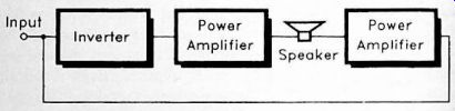
Fig. 1.1 The basic arrangement used in a bridge amplifier.
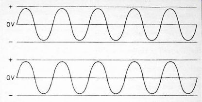
Fig. 1.2
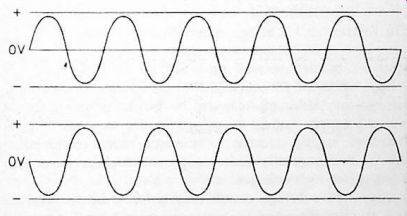
Fig. 1.3
What is needed is anti-phase output signals, as in Figure 1.3.
As one signal reaches its peak negative voltage, the other reaches its peak positive potential, and vice versa. For the sake of this example, assume that each output is producing 20 volts peak to peak. Each output is therefore going to maximum positive and negative values of 10 volts. When one output is 10 volts positive, the other is 10 volts negative. This gives a total of 20 volts across the loudspeaker. Haifa cycle later the signals have swapped states, and there is again one output at plus 10 volts and one at minus 10 volts. This gives 20 volts across the loudspeaker once more, but this time it has the opposite polarity. With first 20 volts of one polarity, and then 20 volts of the opposite polarity across the loudspeaker, this gives a total peak to peak value of 40 volts.
Using a bridge circuit it is theoretically possible to obtain a peak to peak output voltage that is double the supply voltage.
This is not possible using current output devices, but it is certainly possible to obtain peak to peak output potentials that are well in excess of the supply voltage. The output level is roughly double that of a single-ended power amplifier. In terms of output power this actually means that something like four times the normal output power for a given supply voltage and loudspeaker impedance can be achieved using a bridge circuit. Remember that doubling the output voltage also doubles the output current, and that power is equal to voltage multiplied by current. Doubling both the output voltage and the output current therefore gives a quadrupling of the output power.
Using a bridge circuit it is clearly possible to obtain quite high output powers without having to resort to either a high supply voltage or extremely low load impedances. As we have already seen, for 100 watts r.m.s. into an 8-ohm impedance loudspeaker some 28.28 volts r.m.s., or 80 volts peak to peak is required. Using a single-ended transformerless output stage this dictates a supply voltage of at least 80 volts, and what in practice is likely to be an unloaded supply voltage of 130 volts or so. A bridge circuit could achieve the same output power from a supply potential of at least 40 volts, and what in practice would probably be an unloaded supply voltage of about 65 volts or so. This is clearly much more manageable, although it must be borne in mind that the reduced supply voltage is gained at the expense of greatly increased supply current. However, with semiconductor circuits it is generally easier to provide high currents than it is to provide high voltages.
Although a bridge circuit may seem to be an ideal solution to providing high output powers without having resort to high supply voltages, this system does have one or two slight drawbacks. A minor one is that with this type of circuit it is generally a little more difficult to obtain good stability than it is with single-ended designs. The probable cause of this is the fact that the input must be in-phase with one of the outputs. This can easily lead to problems with instability due to stray feedback, it is not usually too difficult to obtain good stability though, and this is not a major drawback.
Something that does tend to be a more major problem is that of obtaining a low quiescent output voltage. With this type of circuit it is normal for the output to be directly coupled to the loudspeaker. There is no strong d.c. component across the outputs, which makes using a large electrolytic coupling capacitor a dubious practice. The circuit could be designed to produce a suitably strong polarizing voltage, but this would upset the symmetry of the circuit, which would be reflected in a significant reduction in the maximum output power.
Direct coupling is a better way of handling matters, but only if the two output voltages are accurately matched under quiescent conditions. In fact the situation is a little more complex than this, as the output voltages must remain accurately matched when the amplifier is being driven. It is very easy to produce a design that has accurately matched d.c. output potentials under standby conditions, but which has a strong d.c. bias across the outputs when the amplifier is driven hard. It is also easy to produce a design which has accurately matched output levels when it is first set up, but which drifts out of balance within a few minutes.
The problem with d.c. offsets across the output is that they produce strong d.c. flows through the loudspeaker. Apart from reduced efficiency in the amplifier, there are the consequences for the loudspeakers to take into account. Strong d.c. levels maintained for a long period of time can apparently result in the loudspeaker cone being permanently offset from its correct resting position. This could affect the reproduction quality, and would certainly reduce the maximum power level that the unit could handle properly.
Although there are potential problems here, they are not Using operational amplifier style dual insurmountable, balanced supply rails, together with operational amplifier style biasing and feedback circuits, will usually ensure that there is no significant d.c. bias across the outputs.
A small but important point to bear in mind when using bridge amplifiers is that neither output is at earth potential.
Furthermore, as d.c. coupling is used, letting one of the outputs come into electrical contact with the earth rail will produce a massive current flow. The fuses might "blow" in time to prevent any damage, but it is quite likely that one or more output transistors would be destroyed before the fuses cut off the supply. Using dual balanced supplies and a central (0 volt) earth rail can minimize this problem by giving minimal differences between the output potentials and the earth voltage. However, this would not necessarily ensure a low current flow in the event of an output being short circuited to earth.
Power Calculations
Calculating the output power of an audio amplifier should be a simple enough matter, but it is a slightly contentious one. In theory, you simply take the maximum loaded r.m.s. output voltage, square it, and divide by the loudspeaker impedance.
For example, 10 volts r.m.s. into an 8-ohm impedance loudspeaker gives 12.5 watts r.m.s. (10 volts squared = 100 volts, divided by 8 ohms = 12.5 watts). If the output voltage is the peak figure, not the r.m.s. one, it should first be divided by 1.414 in order to convert it into an equivalent r.m.s. figure.
For peak to peak voltages divide by 2.828 in order to obtain an equivalent r.m.s. value.
While this is all simple enough, in practice matters are complicated by the fact that few audio power amplifiers are powered from stabilized supplies. As already pointed out, the use of stabilized supplies does have potential advantages, but these are normally outweighed by the disadvantages. In particular, the increased cost and bulk. An advantage of a non-stabilized supply is that it enables short spiky waveforms to be handled better. Although waveforms of this type give very high peak output powers, they produce relatively low current consumptions. Figure 1.4 helps to illustrate this point.
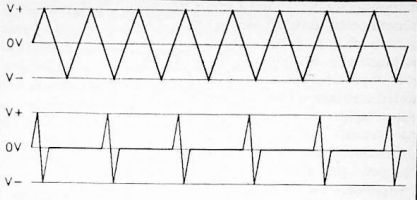
Fig. 1.4 These two waveforms have the same peak power level, but the
average power in the lower waveform is only a fraction of that in the
upper waveform
In the upper waveform, which is triangular, the average level is just half the peak level. In the lower waveform its spiky nature means that the average level is only about one- tenth of the peak level. The peak output power is the same for both waveforms, but the average output power (and current consumption) are much lower for the pulsed waveform. This means that the supply voltage sags relatively little on a pulsed signal, permitting higher peak output powers to be produced. Provided the output transistors have suitably high ratings, on this type of signal relatively high peak output powers can be handled before the onset of clipping.
In a similar vein, it is possible for an amplifier having a non-stabilized supply to provide higher than normal output powers, even with sinewave signals, if they are only supplied in intermittent bursts. This is simply due to the fact that the smoothing capacitors in the power supply circuit will have very high values, and at a middle audio frequency or higher it takes several cycles before these capacitors become significantly discharged and the supply voltage sags. An amplifier might provide 100 watts r.m.s. with a continuous signal, but perhaps about 150 watts r.m.s. or more if it is fed with short bursts of sinewave signal.
This has led to some imaginative output power ratings over the years, particularly for hi-fi amplifiers. Output powers quoted as "continuous r.m.s." in some cases turned out to be figures for something like five cycles at 1 kHz. In other words, "continuous" actually meant for about 5 milliseconds! Some quoted output powers are even less justifiable than this.
Ratings such as "combined music power" seem to be some sort of peak figure, with the powers of the two stereo channels added together. This can give a figure which is ten or more times higher than the true continuous r.m.s. output power per channel.
In this guide all output powers are in watts r.m.s. per channel, and are sustainable indefinitely provided all the components are of adequate ratings, and the power devices are fitted on suitable heatsinks. If you take short cuts by using components of inferior ratings, skimping on the heat
sinking, etc., then this will be reflected in a reduction in the available output power. It will also be reflected in reduced reliability. Using components of inadequate rating, or inadequate heatsinking, is quite likely to result in something over-heating and being destroyed if the amplifier is run at high power for a period of time. The power ratings in this guide only apply if a power supply circuit of adequate rating is used. Remember that the power rating of an amplifier is as much dependent on the power supply as it is on the amplifier itself.
When comparing the power ratings of these circuits with those of other high power amplifiers, remember to check exactly what form the output powers of the amplifiers are given in. Unless you know this, output power ratings do not really tell you a great deal.