AMAZON multi-meters discounts AMAZON oscilloscope discounts
1. The Abe Lincoln Antenna
The Abe Lincoln is, in effect, a slot antenna curved into a cylinder in order to make it less directional than the conventional slot or dipole.
Figure 1(a) shows the dimensions of the antenna in terms of the radiation wavelength X. The position of the antenna lead along the slot length (shown as 0.025X from one end) determines the impedance of the antenna and may be varied to suit the input circuit.
Figure 1(b) shows the polar diagram of a 515 MHz example made from thin card covered with aluminum cooking foil.
Slotted cat-food tins from which the top and bottom have been removed should give a more rugged device working at about 700 MHz.
It must be remembered that a slot antenna is polarised at right angles to the long axis of the slot.
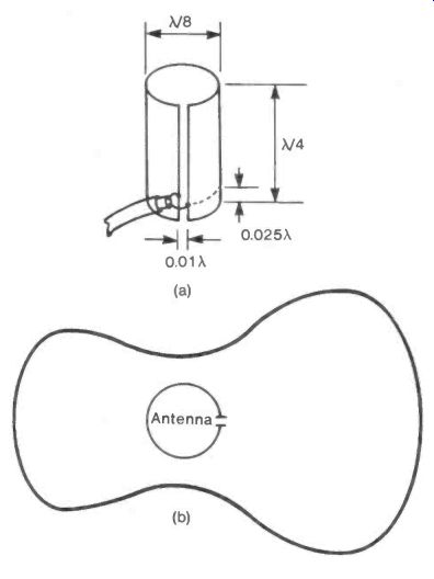
Fig. 1
++++++++++++++++
2. Antenna Impedance Modification
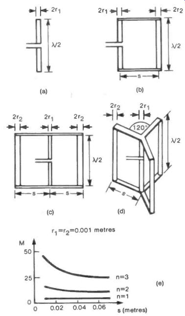
Fig. 2 Antenna Impedance Modification
The basic half -wave dipole has an impedance of ~ 75 ohm.
Figure 2(a) shows such an antenna made with a rod or tube having a radius
r1 and a length X/2. If a second element of length X/2 and radius r2
is joined to it at a distance s, as shown in Figure 2(b), the original
75 ft is multiplied by a factor M equal to:
login ski 2
+ 1) login s/r2
M has a value of 4 if r1 = r2 or, alternatively, if r1
and r2 are both much smaller than s.
Adding a second element symmetrically (Fig.2(c)) makes M equal to:
(2 login s/ri
+ 1)2 logio s/2r2
Three elements added symmetrically (Fig.2(d)) make
the multiplying factor:
(3 logio s/ri logio s/3r2
+ I
In general for n elements added, M becomes:
n login s/r1 I\ login s/nr2 )2 1
This general form that M takes with a multi-element addition is sketched in Figure 2(e) for three values of n when ri = r2. It can be seen that as s gets large, M tends to the value (n + 1)2.
(The apparent zero value of M given when
0+1) = nri nr2 cannot be physically realised as s must be greater
than r1 + r2.)
The ability to adjust the impedance of the antenna to suit the circuit in which it is employed is obviously useful. The most common exploitation of multi-element magnification occurs when a reflector is used, as in a Yagi-Uda array. The action of the reflector reduces the impedance of the dipole to one-quarter of its value when isolated. By using a two element assembly an impedance of 4 x 75 ohm can be obtained.
Reduced to one-quarter of this value by the reflector the standard 75 ohm is retrieved.
As antenna efficiency depends on the ratio of radiation resistance to ohmic resistance, a multi-element structure can be very effective, provided it is matched into its circuit.
+++++++++++++
3. Between Antennas
The results from experiments with widely-separated antennas will be very dependent on the behavior of the radio signal as it travels between transmitter and receiver.
There are two principal forms of signal propagation: the ground-wave and the sky-wave.
The ground-wave follows the earth's surface and has a comparatively short range. Part of its electric field travels slowly in the ground (or the sea) lagging behind that part above the surface and so tilting the wave forward as shown in Figure 3(a). The retarding effect of the ground or sea increases with the frequency of the radiation so the tilt increases also, leading to a rapid absorption of higher frequency signals. Figure 3(b) shows a plot of ground-wave range versus frequency.
The sky-wave depends on the reflection of the signal from one of two layers of free electrons that exist round the earth.
These act on the radio wave rather as a slab of glass would on a ray of light. Striking the layer of electrons at a low angle the wave is merely deflected, but at a large angle it is reflected back as shown in Figure 3(c). (Section 18 gives a mathematical treatment of this behavior of free electron layers.) The lower of the two layers is about 70 miles high and mainly affects signals with frequencies below 1 MHz. This is the Kennelly-Heaviside (E) layer. The upper, or Appleton (F), layer is about 170 miles high and reflects waves of frequency between 1 and 3 or 4 MHz. Both layers are formed by radiation from the sun or outer space, freeing electrons from molecules of air and other gases.
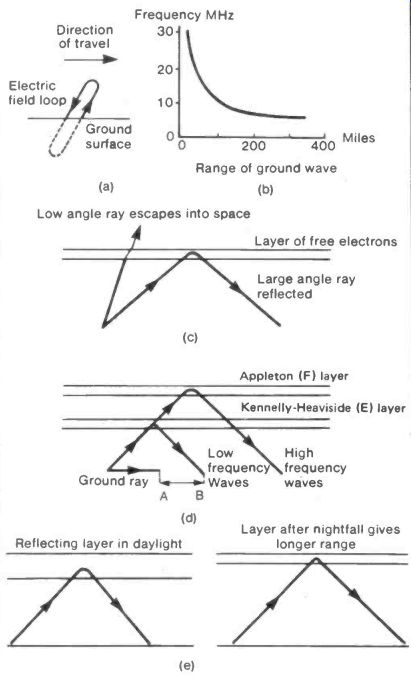
Fig. 3 Between Antennas
Figure 3(d) sketches ground and sky wave behavior.
The region marked A-B is called the dead space, being beyond the ground-wave range but less than the reflected sky-wave travel. No signal can be received in this region.
As the layers are produced partly by solar radiation they will start to decay in the hours of darkness, the lowest part of a layer disappearing first. This causes the layers to become higher in effect and the reflected distance becomes greater as shown in Figure 3(e). The increase in remote radio stations that can be received after nightfall is due to this increase in layer height.
If the frequency of the signal is in the U.H.F. or microwave region it behaves very much like visible light, needing transmitting and receiving antennas to be in line of sight of one another.
++++++++++++++++++
4. Cold Antennas
The efficiency of a receiving antenna is the ratio of the power it passes to its input circuit compared to the total power it absorbs from the radiation falling on it. For a transmitting antenna this becomes the ratio of radiated power to the power fed into the antenna. For both transmission and reception the efficiency depends on the electrical, or ohmic, resistance RE and the radiation resistance RR of the antenna.
In short:
Efficiency E = (Power to circuit)/(power absorbed) or (Power radiated)/(power fed in)
= RR/(RR + RE)
E obviously increases as RE, the electrical resistance, gets smaller and one way of decreasing RE is by reducing the temperature. Figure 4(a) shows how the resistance of a copper wire having a room temperature value of 1 ohm changes with temperature. These small changes in RE would not have a large effect on efficiency if the radiation resistance were to have its usual 75 ohms value, but an antenna deliberately made to have a small radiation resistance would magnify the effect.
One way in which a low radiation resistance can be very simply produced is to reduce the size of a dipole to much less than its normal half-wavelength value. Figure 4(b) shows the effect that such size reduction has on the radiation resistance.
The most dramatic efficiency change occurs when an antenna made from a conducting ceramic material is cooled to the temperature of liquid nitrogen and becomes superconducting. In this state all electrical resistance disappears and the antenna becomes 100% efficient. Although superconducting materials and temperatures are not easily accessible to the amateur, the signs are that they will eventually become commonplace.
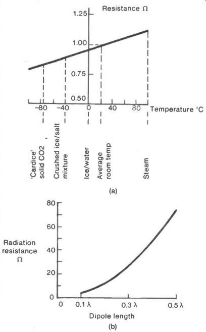
Fig. 4 Cold Antennas
++++++++++++++++++
5. The Crossed Field Antenna
The radio wave, like all electromagnetic radiation, consists of magnetic and electric fields at right angles to one another each rising regularly to a maximum in one direction and then falling to zero before rising to a maximum in the opposite direction, Figure 5(a).
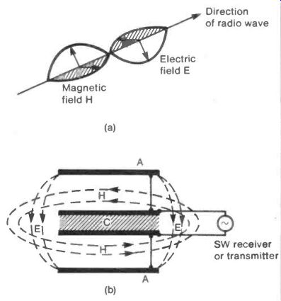
Fig. 5 Crossed Field Antenna
Most antennas use straight conductors designed to produce the varying electric field and let the magnetic behavior look after itself or, less commonly, use a loop designed to produce or detect the magnetic field.
A recently (1989) patented experimental antenna producing both electric and magnetic fields at right angles has been reported as efficient, and also, as insensitive to the dimensions of the structure.
This "Crossed Field Antenna" is sketched in Figure 5(b).
Two metal electrodes A, connected to a radio frequency source (or receiver) produce the varying electric field E, while the displacement current in the parallel plate capacitor C, connected to the same source or receiver produces the magnetic field H.
The two fields are at right angles and they rise, fall and change direction to produce a field system like that in Figure 5(a).
Although the theory has been considered here from the viewpoint of a transmitting antenna, by the reciprocity theory it should also work as a receiving antenna.
There is some argument as to how, or even if, the "Crossed Field Antenna" works and this waits to be settled by experiment.
For a start a simple structure could be tried with the electrodes A formed by tin lids stuck on either end of a 4 to 5 cm long cardboard tube which is slotted to allow the capacitor C to be placed between them. C may be made from similar lids with an air gap of a cm or so between them.
By varying all the dimensions systematically a useful short wave antenna may be made.
++++++++++++++++++++++
6. The Dielectric Clad Antenna
When a radio wave travels in a material with a dielectric constant greater than one its speed is reduced and, consequently, its wavelength is shortened. Thus for instance a half-wave dipole clad in such a dielectric material is smaller than a bare-wire antenna.
Unfortunately all real di-electric materials are lossy and absorb some signal energy producing useless heat, but where a full size antenna is too large for convenience this loss may be offset by the improved "electrical" size of the clad antenna.
An experimental, and approximate, expression for the increase in electrical length when a thin rod is clad in dielectric material is given by
CR 1 + 2 F. d X
R is the ratio of the electrical/geometrical length.
e is the relative dielectric constant of the cladding.
d is the thickness of the cladding.
λ is free-space wavelength.
Water is a convenient experimental material having a dielectric constant of-80 and being easily shaped into cylindrical form by containing vessels. It is then, interesting to test the formula quoted, by considering the length of rod necessary for a quarter-wave element working at a TV frequency of 500 MHz when it is immersed in a bottle of water.
We have e = 80, d is, say, 8cm, and the free-space wave length is 60 cm.
Using these values R is found to be-3.4 and so a quarter wave element would be about 4.5 cm.
An experimental form of water-clad antenna made using a plastic water bottle and some cooking foil is shown in Figure 6(a). Pure distilled water is desirable but tap water will demonstrate the effect.
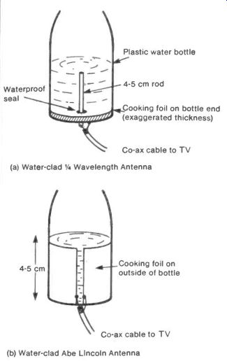
Fig. 6 Dielectric Clad Antennas----------(a) Water-clad V4 Wavelength
Antenna; (b) Water-clad Abe Lincoln Antenna
The slot antenna can also be reduced in size by forming it on a dielectric backing. The Abe Lincoln antenna in particular could be formed by making the slot from cooking foil pasted onto a plastic water container as in Figure 6(b).
Professional work in this field has used Barium/Strontium Titanate as a dielectric material, either in powder form or fired into a ceramic shape.
++++++++++++++++++++++++++
7. Doubly Fed Coax Antennas
Engineers at Birmingham University have developed two forms of antenna with heights of λ/7 and λ/11.
Although the designs give resonant structures despite being much smaller than the standard half-wave dipole, they suffer from a reduced radiation resistance compared with the normal 75 ohm value. This decreases their efficiency and necessitates a matching low resistance value for the antenna circuit.
The antennas are made from co-ax cable folded into U shapes with the dimensions and connections shown in the figure. Antenna as shown in Figure 7(a) has a radiation resistance of--15 ohms and the short-circuited version shown in Figure 7(b) one of-5 ohms.
The ground planes can be mesh or foil sheets with linear dimensions of a wavelength or so, connected to the sheath of a co-ax lead to the antenna.
As always the dimensions cited should be regarded as starting points for experimental variation.
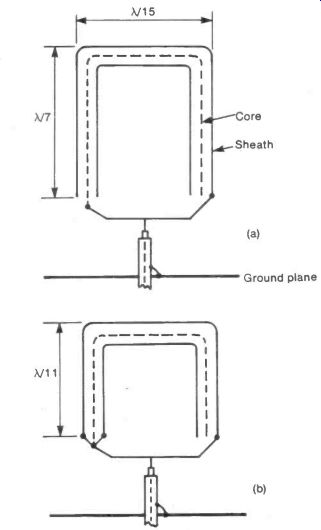
Fig. 7 Doubly Fed Coax Antennas
+++++++++++++++++++
8. Frequency Independent Antennas
A single frequency antenna has dimensions defined in terms of its working wavelength. For example, the design for a 1 meter Yagi-Uda array would be the same as that for a 10 meter array when the element sizes are expressed in terms of wavelength.
Because of this, the design of an antenna which is to be independent of frequency, and hence wavelength, must be based on angles and ratios and not on lengths. The fundamental frequency independent antenna (F.I.A.) is formed from two cones of any convenient angle A, Figure 8(a). In theory the cones should be infinitely tall to respond to infinitely low frequencies. In practice they are made tall enough to work with the lowest frequency used.
Another basic form of F.I.A. is the logarithmic spiral where the radius R of the spiral is related to the angle of rotation 0 by the equation log e R = KO, the constant K being chosen for convenience by the designer. The spiral should thicken uniformly along its length, as shown in Figure 8(b).
The spiral is mounted on, but insulated from, a metal earth plane.
This antenna can be made directional by "pulling it out" into a conical spiral, directional along its axis, as illustrated by Figure 8(c).
The conical spiral can be flattened into a zig-zag form defined by the two angles C and B, see Figure 8(d). Again the angles are at the disposal of the designer.
The most common F.I.A. is the Log Periodic Dipole Array as shown in Figure 8(e), a design using one angle D and one length ratio W greater than one. Note that alternate dipoles are connected in opposition thus cancelling radiation to the side and making the array directional along its axis.
The symbols used in the diagram are:
In the length of the n'th dipole
Rn the distance of the n'th dipole from P
Sn the gap in the centre of the n'th dipole
do the diameter of the n'th dipole.
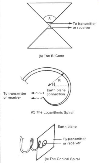
Fig. 8 The Frequency Independent Antenna-------(a) The Bi-Cone; (b) The
Logarithmic Spiral; (c) The Conical Spiral
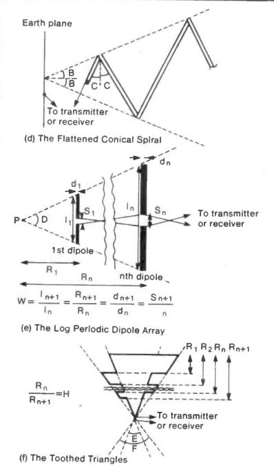
Fig. 8 The Frequency Independent Antenna (cont): (d) The Flattened Conical
Spiral; (e) The Log Periodic Dipole Array; (f) The Toothed Triangles
In use the dipole most nearly 1/2 wavelength long is the active member and adjacent elements act to some extent as the elements in a Yagi-Uda array. The designer has the values of E, W and the total number of dipoles to be used, at his disposal.
A flat approach to the bi-cone of Figure 8(a) consists of two opposing triangular elements. As with the bi-cone true frequency independence would require the triangles to be of infinite height. Failing this their "electrical" length is made as great as possible by slowing down the current flow by cutting teeth into them. Figure 8(f) shows an example where the design is defined by two angles F and E and the length ratio H which is greater than one. All four constants are at the designer's disposal.
It is seen that the concept of an F.I.A. really depends on having a structure that is large compared with any wavelength that may be used, and of a form that allows the radiating or receiving activity to be concentrated on that part of the antenna which offers resonance at the working wavelength.
In the absence of infinitely large antennas there can be no true frequency-independent-antennas; only wide-band devices.
++++++++++++++++++
9. Gain and Efficiency
The gain and the efficiency of an antenna are two distinct and equally important characteristics.
The gain depends on the radiation power collected compared with that which a standard half-wave dipole would collect in the same radiation field. It is usually expressed in decibels and, written in full, is:
(Power collected by antenna)
Gain = 10 x log10
(Power collected by standard dipole)
This rather clumsy expression is the standard form for antenna gain. The gain is closely linked to the directionality of the antenna. If it radiates into, or receives from, a cone with an angle A then, as A gets bigger, the gain gets smaller. At first this seems to be the wrong way round, but it can be under stood by considering a dish reflector used with an antenna.
The bigger the dish the more nearly parallel is the transmitted radiation. This corresponds to a small value of A, see Figure 9(a). However the bigger the dish then the greater is the amount of radiation collected also, and so the greater the gain.
In contrast to the gain, which is concerned with how much radiation power is collected, the efficiency is concerned with how much of that power is wasted and how much is made available at the antenna terminals. This can be written:
(Power available at antenna terminals)
Efficiency =
(Total power collected)
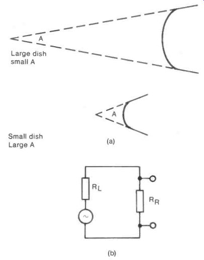
Fig. 9
It is perhaps helpful to think of the antenna as an a.c. generator with an internal resistance RL representing the source of power loss in the antenna. This is connected to the "useful" radiation resistance RR, as illustrated by Figure 9(b). The total power in the circuit is proportional to the gain G. The useful fraction of this is RR /(RR + RL) and so the antenna output is proportional to:
G x RR (RR + RL)
The fraction RR/(RR + RL) is the efficiency and so finally:
Antenna Output is proportional to Gain x Efficiency
The same values for the gain and the efficiency hold for a given antenna whether it is used for transmission or reception.
+++++++++++++++
10. Helical Antennas
If a length of wire is wound into a helix and used as an antenna it will radiate and receive at right angles to its axis if the total length of the wire used is much less than one wave length, or it will radiate and receive along its axis if the wire length is much greater than one wavelength, as illustrated by Figure 10(a).
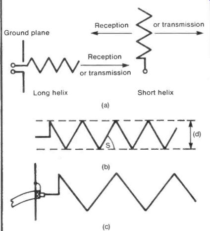
Fig. 10 Helical Antennas
The three numbers defining a helical antenna are:
L the total length of conductor used
(not the length of the helix)
d the diameter of the helix; and
s the pitch of the helix.
These are shown on Figure 10(b).
In the first case take a "long" helix. Experiments could start with L- 5X, d- X/3 and s- 10°. A stout cardboard cylinder can be used to support the helix with a metal plate, or mesh, connected to the braid of a co-ax lead for the ground plane, see Figure 10(c). This should give some ten times gain over a half wave dipole, a gain that increases with decreasing s.
The action of the long helix is an interesting border-line case between that of a waveguide (as in microwave practice) and that of an orthodox antenna.
The short helical antenna is basically a quarter wave mono pole wound into a helix to shorten it for convenience in portable or mobile use. A reasonable gain is still possible even if L has less than its optimum X/4 value. A self-supporting wire structure can be formed by coiling thick copper wire onto a pencil. Removed from the pencil the coil can be stretched out as far as desired. The problem with the short helical antenna is the reduction in radiation resistance, and hence efficiency, it shows compared with a full size X/4 antenna.
+++++++++++++++++++
11. Inductance Design
The unit of inductance is the henry but this is so large that most texts deal in microhenrys, the one millionth part of the henry. The symbol for the microhenry is µH.
The inductance L of a long, thin coil is given by the formula:
L = (K.N2 D2 VIZ µH
Here N is the number of turns on the coil D is the diameter of the coil in meters Q is the length of the coil in meters K is the permeability of the core material equal to 1 for air.
This formula is accurate if Q is much greater than D.
For a short coil a correction factor must be used. Where a winding of thickness d is used on a short coil, as in the Figure 11, the inductance L is given by:
L = K.N2(D- d).F pH
where F is a correction factor depending on the magnitude of (D- d)/(Q + d). F can be read from the graph.
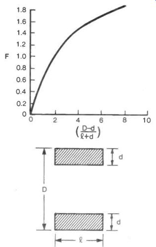
Fig. 11 Inductance Design
++++++++++++++++
12. Interference Effects
Note: It is unfortunate that "interference" has two separate meanings in radio science. It can be applied to intrusive electrical noise or static, but in this section it refers to the manner in which two similar radio waves can cancel one another if they are 180° out of phase, or reinforce one another if they are in phase.
When radiation falls on a slit or aperture that is broad compared with the wavelength of the radiation, it passes straight through with no change of direction, see Figure 12(a). If the width of the slit is made so small as to be comparable with the wavelength then the slit will behave as a radiating source, see Figure 12(b). This allows radiation to be focused by using a number of narrow slits set at a particular distance apart. In Figure 12(c) the three rays that converge on F from the parallel radiation falling on the slits S1, So and S1' will reinforce one another if the distances S1.F, and S11 .F are one wavelength greater than So .F. This condition of constructive interference between the rays requires that the slit separation h satisfies:
h2/So.F- 2X
By making the central slit a circular disc and the outer slits into a ring or annulus a conventional circular lens known as a Fresnel Zone Plate is formed. This type of lens is commonly used with visible light and focusing has been demonstrated with microwave radiation.
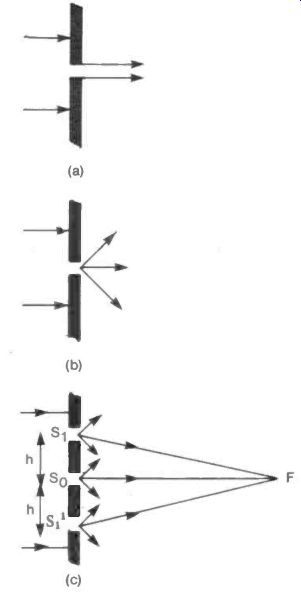
Fig. 12 Interference Effects
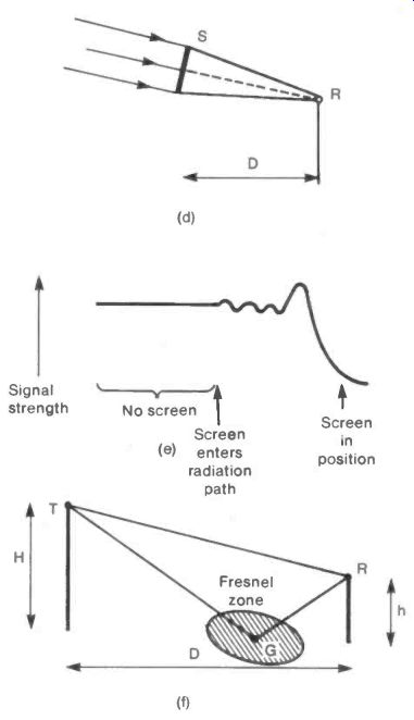
Fig. 12 Interference Effects (cont)
An interesting experiment would be to examine the effect at TV wavelengths. If the outer slits of Figure 12(c) are set 1.5 meters from the central slit, a half-wave dipole some two meters from the slit system should receive a focused signal.
The slits must be parallel with the direction of polarization of the television signal. Alternatively if the experiment is made with the 2.7 cm radiation of satellite TV a much less cumber some slit system results with all distances divided by about 20.
The interference effect on signal strength when certain parts of a beam of radiation are blocked, not only occurs for systems of slits but can be shown when a single circular screen is placed between the receiver and the incoming radiation. In Figure 12(d) the circular screen S is introduced into radiation from a remote transmitter. With the screen a distance D from the receiver R its radius must be radic (D x Lambda) . As it enters the radiation path the signal strength will at first oscillate, then rise to a peak and finally fall to a minimum as suggested in Figure 12(e).
Cooking foil should provide a satisfactory screen material and again, the experiment is less cumbersome with the satellite radiation.
The ground is in general a good reflector of radio waves and radiation reflected from a central point between transmitter and receiver can interfere with the direct ray. In Figure 12(f) a ray from the transmitter T reflected from the ground at G to a receiver R travels a distance-- 4 H.h/D farther than the direct ray. If this value of 4 H.h/D is equal to X the two signals will reinforce one another, if equal to X/2 they will cancel. It is sufficient for some interference to happen if these relationships are only approximately true. Because of this, reflection from an area surrounding G will be effective. This area is roughly oval and is known as the Fresnel Zone.
If the formula for the two interference conditions are written in terms of the receiver height h:
and hmAx = D.X/4.H h mIN = D.X/8.H for a maximum for a minimum and so the separation between receiver heights for a maximum and a minimum is D.X/8.H
+++++++++++++++++++
13. Long and Short Dipoles
The standard half-wave dipole consists of a straight conductor just less than half a wavelength long, broken at the centre to take the lead from the signal as shown in Figure 13(a). Such a dipole mounted at least three wavelengths above the ground would behave like a pure 75 ohm resistor without inductance or capacitance. This 75 ohms can be increased by moving the point at which the lead is introduced towards the end of the antenna, see Figure 13(b).
If for any reason, the dipole has to be reduced in length below 0.48X it will behave as though a capacitor were added to the resistance. This capacity can be removed by making the dipole longer electrically than it is physically. One method of doing this is discussed in the section on dielectric-clad antennas but it may also be done by introducing an inductance into each arm of the dipole. Experiment could start with inductances formed by winding some ten turns of wire onto a pencil with a tapping point taken at each turn.
With a coil placed in each arm symmetrical tapping points can be chosen for maximum signal, as illustrated by Figure 13(c).
If the signal shows an increase right up to the point when all the turns of the coil are in circuit then coils of larger diameter should be wound and tried. If the signal increases up to the point when only one turn is in use, then smaller diameter coils should be tried.
If the dipole length is greater than 0.48X then it will behave as an inductance. This is a less common problem than the short dipole but it has the obvious remedy of putting series capacitors in each arm, see Figure 13(d). Variable capacitors of 500 pF, preferably ganged together, should be tried.
Fig. 13 Long and Short Dipoles--- F Dipole less than Equivalent
0.48X long circuit; Capacity compensated by inductances; F Dipole greater than Equivalent
0.48X long circuit Inductance compensated by capacitances
++++++++++++++++++++