AMAZON multi-meters discounts AMAZON oscilloscope discounts
14. Loop and Frame Antennas
A resonant single-turn loop antenna for use with V.H.F. or U.H.F. radiation is of a reasonable size for domestic use. Such loops have been reported as giving 10 times the signal obtained from a simple half-wave dipole. The loop should be in the form of a circle with a diameter of between 1/3 and 1/2 a wavelength. One end of a gap in the loop is connected to the sheath of a co-ax cable, the other to the core. It is mounted about 1/4 of a wavelength above a large area metal ground plane, both the loop diameter and the height above the ground plane being varied experimentally to find the best values, see Figure 14(a).
When working in the medium and long wave regions any practical loop or frame antenna will be small compared with a wavelength. The undesirable result of this is a low radiation resistance for the antenna. If n turns of wire are wound onto a frame having an area of A square meters as shown in Figure 14(b) the radiation resistance will be:
1.6 x 10⁴ (nA/X2)2 ohms .
It will have the same effective length as a straight wire antenna of length:
2frnA/X meters .
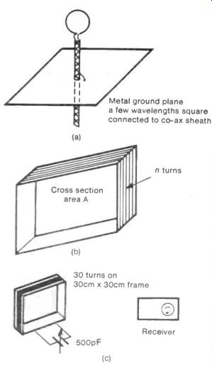
Fig. 14 Loop and Frame Antennas-----------Metal ground plane a few wavelengths
square connected to co-ax sheath; 30 turns on 30cm x 30cm frame
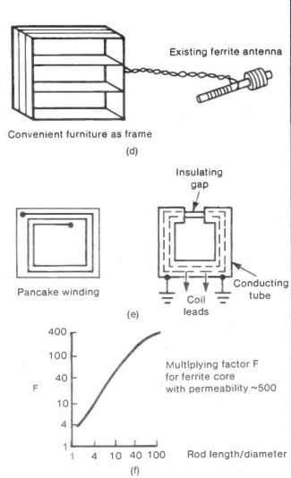
Fig. 14 Loop and Frame Antenna (cont)-------- Convenient furniture as
frame
Calculating the radiation resistance and effective length for a real case will give an idea of the characteristics of a medium or long wave frame antenna. Suppose 50 turns are wound on a square of 0.5 meter side and used at 500 meters wavelength (600 kHz). The radiation resistance would be 4 x 10⁵ ohms and the effective length 16 cms.
These values do not make for a very efficient antenna but it would have the advantage, like all frame antennas, of being highly directional, receiving or transmitting signals only at right angles to the axis of the frame. This property can be particularly useful after dark when radio stations tend to crowd the wave-bands.
One interesting form of frame antenna that has been reported consisted of a cardboard grocery box about 30 cms by 30 cms wound with 30 turns of wire. The ends of the winding were connected to a 500 pF variable capacitor. The frame was placed near to a receiver but not electrically connected and the position of set and frame and the capacitor setting all adjusted for best signal, see Figure 14(c). It needs to be set up using a weak station otherwise the action of the automatic gain control on the receiver will obscure any increase in signal provided by the frame.
A more conventional frame antenna can be formed by winding 2-3 turns of wire round a frame with an area of some two square meters. (One experimenter used a convenient bookcase as a frame.) The ends of the winding are led by ordinary twisted flex to the existing ferrite rod in a receiver and the flex is looped once around the ferrite rod, this is illustrated by Figure 14(d).
The directional properties of a frame antenna can be improved by winding the wire in a flat pancake form rather than in a box form. Another method of improving the directionality is to enclose the coil in an earthed conducting tube or sheath with a well-insulated gap in it to prevent circulating eddy currents, as shown in Figure 14(e). Both of these techniques reduce the sensitivity to signals in the direction of the coil's axis.
The introduction of a ferrite core into a coil can greatly increase the signal from it. This means that very small coils having such cores can form satisfactory miniature antennas.
The multiplication of the signal depends on the permeability of the ferrite and the length/diameter ratio of the rod.
Figure 14(f) shows the multiplication factor that a ferrite core with a permeability of 500 has with various length/ diameter ratios.
++++++++++++++++++++++
15. Matching and Balancing
A problem with experimental antennas, or indeed any antenna, lies in matching the antenna to its circuit so that power is not reflected back from the circuit, if receiving, or back from the antenna, if transmitting.
If the impedance of the antenna consists of a resistance plus a reactance then the circuit must have an equal resistance and an equal and opposite reactance. Opposite, as regards the reactance, means that a capacitive antenna must have an inductive circuit and vice-versa.
If these conditions are not satisfied extra impedances have to be introduced between the antenna and its circuit as shown in Figure 15(a). The values of the impedances Zp and Z, are:
Zp = N/Zc(Zc- ZA)
ZS = ZA Zc/(Zc-ZA)
where ZA is the antenna impedance and Zc is the circuit impedance.
The two impedances can be introduced very neatly by the technique known as stub matching shown in Figure 15(b).
A distance A along the line connecting antenna and circuit, a short stub of line length B, is connected across the line. The length of line A acts as the series impedance Z, and the length B as the parallel impedance Zp in Figure 15(a). The values of these impedances depend on the lengths A and B and, in the case of the latter, on whether the end is short-circuited or open-circuited.
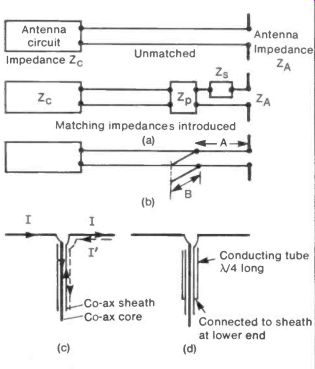
Fig. 15 Matching and Balancing
The lengths A and B are usually found by experiment but a guide to the behavior of short lengths of transmission line when used as impedance is given in Table 15.1. Here A' is the wavelength of the radiation in the line which is usually shorter than the free-space wavelength.
Another problem occurs when an antenna having two similar elements, as in a half-wave dipole, is connected to its circuit by coaxial cable. Ideally one current I flows in the central core, while an equal current flows in the opposite direction in the sheath as shown in Figure 15(c). However, because the sheath is usually earthed a second unwanted current flows to earth in it. To choke off this undesired current the cable can be surrounded with a quarter wave length conducting tube connected to the sheath at its lower end as in Figure 15(d). This then forms an infinite impedance for the radio-frequency currents, stopping the undesired current flow. The tube can be formed from cooking foil or, more elegantly, by painting the outer insulation of the coaxial cable with conducting silver paint.
The device is called a ‘balun' as it is used to link the balanced electrodes of the antenna to the unbalanced leads of the cable.
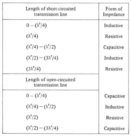
Table 15.1
+++++++++++++++++
16. The Phased Array
A simple phased array could be made from two antennas a set distance apart, each fed from the same transmitter or receiver.
The distance between the antennas and the length of cable between them will then govern the direction in which they radiate, or from which they receive.
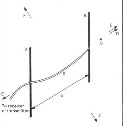
Fig. 16 The Phased Array
In Figure 16 two dipoles A and B are a distance a apart and, while A is fed directly from the circuit, B receives the signal after passing through a delay line of length Q. At a point C in line with A and B the signal will have travelled a distance (Q- a) further from antenna A than it has from B.
If (Q- a) is equal to a whole number of wavelengths the signals will reinforce one another in the direction of C. If (2- a) is equal to an exact number of half wavelengths the signals will then cancel one another in the direction of C.
By choosing 2 and a, the direction of the maximum emitted or received signal can be selected. Table 16.1 below, shows some "2" and "a" values with the consequent directions of reception or transmission.
The many and various forms of phased array are discussed more fully by E. M. Noll in his book "25 Simple Amateur Band Aerials" (BPI 25) published by Bernard Babani (publishing) Ltd in 1983.
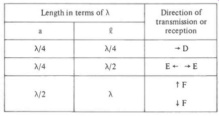
Table 16.1
+++++++++++++++++++
17. Reflecting Elements
The addition of a reflector to an antenna concentrates the emitted or received radiation into a smaller angle. This improves the gain but, as it changes the radiation resistance of the antenna as well, it will also alter the efficiency.
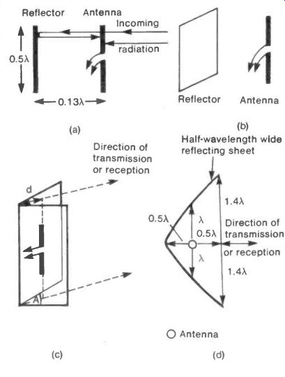
Fig. 17 Reflectors
The reflector can be either tuned or aperiodic. The typical tuned reflector is a 0.5X long rod set around 0.13X behind the antenna, as shown in Figure 17(a). The rod and the antenna both have currents excited in them and the two radiations from these two currents co-operate to reinforce forward radiation, or reception, according to whether the antenna is transmitting or receiving.
The aperiodic reflector is in effect a large metallic surface acting on the radio-signal much as a mirror would on visible light. In its simplest form it consists of a flat sheet of metal replacing the tuned rod behind the antenna, see Figure 17(b).
The dimensions of the sheet are not critical, even a half-wavelength square has an effect and the reflector may be made from a wire mesh, provided the mesh dimensions are much smaller than a wavelength.
The corner reflector is a more elaborate and effective structure. It consists of two sheets of reflecting metal set at an angle A, as shown in Figure 17(c), with a half-wave dipole set symmetrically a distance d from the apex of the sheets.
The reflecting sheets should be about two wavelengths tall and one wavelength wide. They can be cheaply made from cardboard from grocery cartons covered with cooking foil.
The performance of the corner reflector depends on the adjustment of A and d. The efficiency and gain both vary with these two factors and the best values must be found experimentally, starting perhaps with A'- 90° and d 0.5X.
The most effective reflector for a communication system between two fixed points is the dish seen in microwave links and satellite TV installations. Although dish construction is rather specialized, what in effect is the section of a dish, can be made by bending a half-wavelength wide reflecting sheet into the form shown in Figure 17(d). A half-wave dipole antenna is placed at the position shown in the figure with its arms parallel to the reflecting sheet.
+++++++++++++++++
18. Refractive Index of Free Electron Layers
In Section 3 the various atmospheric layers carrying free electrons were treated either as transparent to, or as reflecting, radio waves. In this section a more detailed look at their behavior is taken. The analysis is quite long but straight forward.
The electric current J that flows in free space when a radio wave passes through it is related to the absolute dielectric constant co by the expression:
J = codE/dt
where dE/dt is the rate of change of the electric field in the radio wave. For a field of amplitude E0 volts/meter and a frequency f Hz the value of E at any time t is given by the equation:
E = E0 sin 2 pi ft .
Differentiating both sides of this equation with respect to time t gives:
dE/dt = 2 pi fE0 cos 2 pi ft .
From the above formulae it can be shown that:
J = co 2 pi fEo cos 2 pi ft .
In the presence of free electrons an additional current Je flows and this current must be calculated. The force of an electron in an electric field due to its charge e will be:
E.e = E0 sin 2 pi ft .
By Newton's Law this is equal to the electron mass m multi plied by its acceleration d2x/dt2 in the direction of the electric field.
e E0 sin 2pi ft = md2 x/dt3 .
Integrating both sides of his equation with respect to t gives the velocity dx/dt as:
dx e Eo cos 2 pi ft
dt 277mf If the electron density in the layer is N per meter; then the current density Je is given by:
J =-e N x dx/dt e2N E0 cos 2 pi ft 2 pi mf
We now have:
Total free space current J = co 2 pi flo cos 2 pi ft
Total current in electron layer:
(J + Je) = Co 2 pi fE0 cos 2 pi ft-
Ne2 E0 cos 2 pi ft 2 pi mf
Using previous equations shows that the ratio of currents (J + Je)
= Ratio of absolute dielectric constants J CEO
=- = e the relative dielectric constant eo NO = 1 _ 4772 mr2E0 (9
Putting in the constants
= 1-N-
f/
Now the refractive index µ of a material is equal to the square root of the relative dielectric constant and so for the free electron layer
= 1- N(9/02
The refraction or bending that a radio wave will suffer when striking a free electron layer can now be determined by using Snell's Law:
sin (angle of incidence) P sin (angle of refraction) See Figure 18.
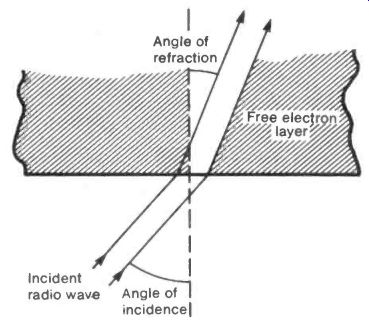
Fig. 18 Refractive Index of Free Electron Layers
If N(9/f)2 is greater than 1, µ becomes imaginary and the layer is effectively transparent.
If N(9/02 is less than 1 then Snell shows that radiation will be refracted but still pass through the layer unless the angle of incidence is greater than
sin-i V 1- N(9/f)2
when it will be reflected back to earth.
++++++++++++++++++++++
19. The Skin Effect
Domestic tv. antennas are often made from metal tubing rather than solid rods or wires. It seems at first sight that this would make the antenna elements into poor conductors, having only a thin shell of metal for the current flow. however, because of the phenomenon known as the "Skin Effect", the loss of conductance shown by a tube as compared with a rod can be very small at high frequencies.
If a direct current is passed along a wire it will flow uniformly through the entire cross-section whereas a radio-frequency current will be crowded into the outer skin as shown in Figure 19.
Wire carrying low frequency or direct current
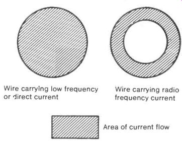
Fig.19 Skin Effect: Wire carrying radio frequency current; Area of current
flow
The higher the frequency of the current the thinner this skin becomes, while, at very low frequencies such as the 50 Hz of the domestic supply, the skin is so thick that the effect can be ignored.
To calculate the skin thickness t from the conductivity a of the wire and the frequency f of the current the formula
0.5 t- meter
can be used. Here f is measured in MHz and a in siemens/ meter. As an example a copper wire carrying a 10 MHz current would have a skin-depth of 0.02 millimeters.
The effect is also seen when radiation falls on a metal sheet. The depth of penetration of the radiation into the metal depends in the same way on the radiation frequency and the conductivity of the metal.
The cause of the skin effect lies in the magnetic field produced by a current-carrying wire. If the current is varying, then the magnetic field also varies and produces eddy-currents in the wire which oppose that part of the applied alternating current in the centre of the wire.
+++++++++++++++++++
20. Sky Wave Antenna
A method has been reported for improving the signal given by a built-in whip antenna when receiving H.F. sky wave transmissions.
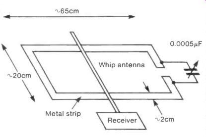
Fig. 20
A horizontal loop of metal strip with the approximate dimensions shown in Figure 20 has a gap bridged by a 0.0005 AF variable capacitor. The receiver whip is laid across the loop but not in contact with it and its position, and the setting of the capacitor, are adjusted for maximum signal.
The loop is conveniently made with cooking foil stuck to the underside of a bench or work table.
++++++++++++++++++
21. Standing Wave Interference in Domestic TV
(See the note heading Section 12) In general a domestic TV antenna is required to receive eight different wavelengths to give sound and vision for four stations. For example the Sandy Heath Beds transmitter uses the following:
Station
Channel 4
ITV
BBC 2
BBC 1
Vision Frequency
(MHz)
471.25
495.25
519.25
551.25
Sound Frequency (MHz)
477.25
501.25
525.25
557.25
... giving a wavelength range from 0.64 to 0.54 meters. This gives no problem unless the signal is reflected from a nearby structure in which case the two radiations, direct and reflected, can interfere with one another. If the direct and reflected path-lengths differ by an exact number of half-wavelengths then the received signal will be reduced to a minimum. If they differ by an exact number of whole-wavelengths the signal will be a maximum.
In Figure 21(a) a remote transmitter T gives a direct signal to an antenna A and a second signal reflected off a structure R. If R is at a height h greater than A, and a distance r from it, then the vertical separation of maximum and minimum signal positions will be:
X r 2h
If the antenna is moved horizontally towards or away from the transmitter the maxima and minima will be separated by
Ar 2 Vr2- h2
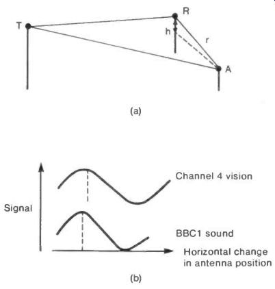
Fig. 21 Standing Wave Interference in Domestic TV--- Channel 4 vision
BBC1 sound Horizontal change in antenna position
As an example let h = 10 and r = 50 meters then the vertical separation is 2.5X and the horizontal separation is 0.5X. The extreme values calculated for the Sandy Heath Channel 4 vision, and BBC 1 sound, max-to-min separations are shown to scale in Figure 21(b).
With the maximum and minimum patterns of eight different wavelengths to satisfy, the positioning of the antenna to give a maximum for them all can be a laborious business of trial and error.
It is sometimes possible to locate the reflecting object by measuring the max-min distance and then calculating h/r, then finding a structure with a position that satisfies this ratio.
+++++++++++++++++++++++++
22. Substitutes for V.H.F. Whip Antennas
The whip antenna normally used on the V.H.F. domestic radio is inconvenient and sensitive to the movement of people in its vicinity.
Two compact substitutes have been developed for use in its place. The first, patented by the Royal Military College of Science consists of a normal ferrite rod as used in medium wave and long wave receivers with sets of reversed windings along its length as shown in Figure 22(a). After three or four turns in one direction the direction is reversed for another set of turns, all being wound from one continuous wire. Results using a rod about 1/22 of a wavelength long were reported as satisfactory for reception between 79 and 94 MHz. Exact tuning of the antenna was done by winding an excess of turns on the rod and then successively cutting turns off until the best performance was obtained. The report on this antenna suggests that all dimensions and even the rod materials are open to experiment for optimizing the performance.
A different substitute for the whip has been examined by the B.B.C. Research Department. In this a rod of special high frequency ferrite (Neosid F29) which has very little loss up to 100 MHz is used in the manner similar to the ferrite rod antenna in medium and long wave radio. The tuning coil consists of three turns of wire, and the coupling coil of two turns. Figure 22(b) shows a schematic of the arrangement.
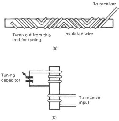
Fig. 22 Substitutes for V.H.F. Whip Antennas
+++++++++++++++++++
23. Thermal Noise in the Antenna
The heat or thermal radiation which falls on an antenna from its surroundings produces a small alternating voltage in its output. This "noise" voltage in a simple dipole depends on:
Q the dipole length
X the wave length
(f1- f2) the range of frequencies accepted by the antenna circuit
T the thermodynamic temperature of the antenna surroundings, and the equation for the voltage V is:
V = 10-10 . (Q/X) NiT(ft- f2) volts.
In practice the antenna will not be surrounded by a uniform temperature but will, for example, be subject to sky radiation with a temperature of- 5°K, horizon radiation at 100-150°K and ground radiation at- 300°K and the noise temperature will take some average value, see Figure 23.
This average will depend on the polar diagram of the antenna, the dominant value being the temperature of the region which the antenna "sees" most strongly.
To obtain the effective noise temperature of an antenna where the open circuit value of V is known, the above equation can be rearranged:
T = (1010. V . X/Q)2/(f1- f2) .
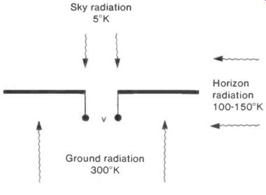
Fig. 23 Thermal Noise in the Antenna
+++++++++++++++++++++++
24. Use of a Parasitic Element
A single straight rod or conducting wire placed near to, and parallel with, a half-wave dipole can be made to increase the signal collected either by guiding radiation onto the antenna or reflecting back radiation that has passed it.
This guiding or reflecting electrode is not connected to the antenna circuit electrically and so is called a parasitic element.
Used as a guide it is a director and, if used to reflect radiation back to the antenna, it is of course a reflector, as illustrated in Figure 24(a).
The reflector and director differ only in their length and their distance from the antenna. The reflector is a little longer than half a wavelength and the director a little shorter, the exact amount for optimum performance depending on the parasite-to-antenna distance. A guide to parasite lengths and antenna distances is sketched in Figure 24(b). Note that the scale for h differs in the two graphs. It is seen from these that a change of a few percent in the parasite length can turn a director into a reflector and vice-versa. Alternatively a parasite of a given length will direct or reflect according to the signal wavelength.
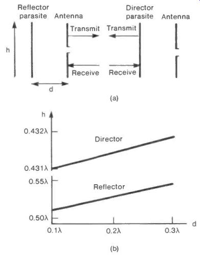
Fig. 24 Parasitic Elements.
+++++++++++++++++++++++
25. Using the Pattern of TV Signal Maxima
Due to interference the signal strength of terrestrial TV in most areas forms a regular pattern of maxima as the sketch in Figure 25(a) suggests. This pattern can be mapped out using a half-wave dipole antenna connected to a domestic TV receiver. The searching antenna can conveniently be mounted on the end of a broom-stick to minimize interference from the operator's body, and swept in a regular path to locate a number of maxima.
By placing several antennas at well separated points of maximum signal, considerable power may be collected, see Figure 25(b).
The array of antennas must be matched to the standard 75 ohm input of the receiver. If, for example, three antennas are to be used, each should be designed according to the section "Multi Loop Antennas" to have a radiation resistance of 200 to 250 ohms. The leads should also match and these can be made from parallel wires of radius r set a distance d apart. They will have a radio frequency impedance of 276 . logo (d/r) ohms .
Generally r will be fixed by the wire available leaving d to be adjusted to give the 200 to 250 ohm value required, see Figure 25(c).
The leads from the three antennas should be connected in parallel to a standard co-ax cable going to the t.v. receiver.
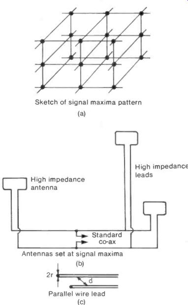
Fig. 25 Using Pattern of Signal Maxima-------Sketch of signal maxima pattern
(a); Antennas set at signal maxima (b); Parallel wire lead (c)
+++++++++++++++++++
26. Wave Traps
A single antenna can be made to serve two different wave lengths by making use of wave traps. In principle the overall length of the antenna is made suitable for the longer wave length radiation and a break is made in it to give a length for use with the shorter wavelength. The break is bridged by a wave trap which must act like a switch, open to the longer wavelength signal and closed to the shorter, see Figure 26(a).
The wave trap can be formed by a capacitor C and an inductance L in parallel, Figure 26(b), making a rejector circuit tuned to impede, or reject, the higher frequency, shorter wavelength signal.
Dimensions for a dipole system to receive both 90 MHz and 600 MHz are shown in Figure 26(c). Each wave trap uses a 500 pF variable capacitor connected across a coil of 5 turns wound along a length of 5 cms on a 1 cm diameter tube.
As always, all dimensions should be regarded as starting points for experiment.
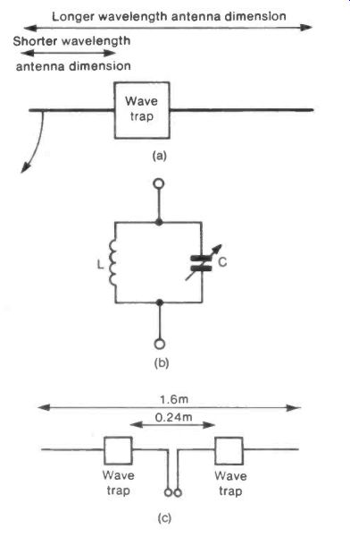
Fig. 26 Wave Traps---Longer wavelength antenna dimension
Shorter wavelength antenna dimension
+++++++++++++++++++
27. The Windom Antenna
The Windom is a very basic antenna consisting of a single wire or conducting rod with a lead tapped off part way along it.
It can, nevertheless, give a signal voltage at least 80% of that from a standard half-wave dipole. Figure 27(a) shows the approximate dimensions of a Windom antenna which is to be operated at a wavelength λ. These dimensions should be taken as the starting point for experiment, particularly in the location of the tapping point A.
A method for making the antenna out of a single conductor without mechanical or electrical joints is suggested in Figure 27(b).
Figure 27(c) shows the dependence of the signal voltage, taken as the percentage of that given by a half-wave dipole, on the position of the tapping point A, when a Windom antenna was used to receive a 510 MHz TV signal.
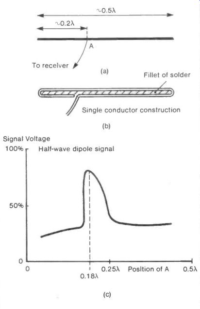
Fig. 27 Windom Antenna
+++++++++++++++++++++++
28. Yagi-Uda Array
This antenna was originally devised by Professor Yagi and his student Uda to radiate and receive large amounts of energy rather than communicate information, and it did indeed beam enough power to charge a storage battery. The operation was interesting rather than efficient and nowadays the Yagi-Uda array is used only for telecommunication.
There are three basic elements in the array as shown in Figure 28(a):
(1) The antenna or exciter connected to the receiver or transmitter.
(2) A reflecting assembly behind the antenna.
(3) A set of directors in front which guide the radiation towards the antenna for reception or away from it for transmission.
The reflector can be a single rod 0.5X long (i) or, more efficiently, three such rods set parallel and a distance 0.5X apart (ii). A metallic sheet or close mesh of wire can also form a reflector (iii).
The antenna is set about 0.13X away from the reflector and may be a half-wave dipole (iv), or a folded half-wave dipole (v). Since the presence of a reflector reduces the impedance of the antenna, the use of the high impedance folded dipole helps to restore a standard impedance value.
A patented antenna recorded as giving a broad frequency response is in the form of an isosceles triangle with a 0.5X base and an apex reaching back almost to the reflector (vi).
The two equal sides need to be about 0.3X long.
The directors are rods or elements about 0.4X long, the first set at 0.3X from the antenna (vii). Any number of directors can be used at further intervals of 0.3X but each added director becomes less effective as the number is increased, see Figure 28(b).
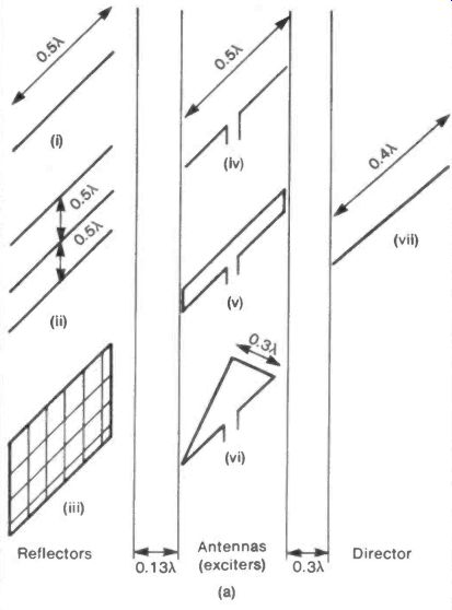
Fig. 28 Yagi-Uda Array
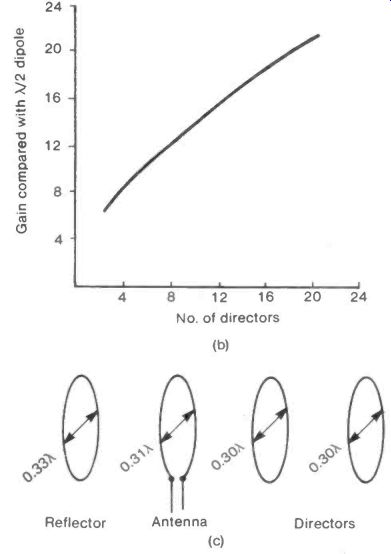
Fig. 28 Yagi-Uda Array (cont)
A variation of this form of array uses circular loops in place of the dipoles or mesh. The values for the loop diameters could be 0.33X for the reflector, 0.31X for the antenna and 0.30X for the directors with the separations between elements being similar to those in the dipole array, this is illustrated in Figure 28(c). This form of Yagi-Uda array has been reported as showing a bigger gain than the more usual form.
All the element shapes, sizes and separations cited should be regarded as the starting points for experiment.