The video signal from a color-TV transmitter actually consists of two separate signals. These are the luminance and chrominance signals.
To properly understand the color TV transmission system, we must study the make-up of these signals at the transmitter.
The scene to be televised is viewed by a tricolor camera which receives white light from the scene and produces three signals representative of the red, green, and blue components of that white light. Fig. 1 shows the basic components of the tricolor camera.
The white light from the scene is focused by the optical system and is directed onto the dichroic mirror at A. This type of mirror is designed and manufactured to pass all light frequencies of the spectrum except those of one particular primary color. Thus the mirror at A reflects blue light and passes all the other light. The beam of blue light is directed onto a front-surface mirror at B and thence onto the photo surface of the blue camera tube.
The light passing through the mirror at A strikes another dichroic mirror at C. which is designed to reflect red light. The red beam is directed to a front-surface mirror at D and thence to the red camera tube. The light beam passing through mirror C is devoid of blue and red and contains only green light; thus it goes directly to the green camera tube. We can see that the light from the scene being televised has been broken up into the three primary colors.
The three camera tubes and their associated amplifiers develop three voltages which are representative of the three colors. These voltages we will designate as ER for red, E6 for green, and E for blue. We will go on to see how the luminance and chrominance signals are formed from these three voltages.
The Luminance Signal
In order for the color signal to be compatible with black -and -white receivers, one portion of the signal must represent the televised scene in terms of brightness only and must be very similar to the video signal specified for monochrome transmission. This signal is called the luminance signal.
When the specifications for this luminance signal were being drawn up, the response of the human eye to light of different frequencies was considered. The human eye does not see all colors with equal brightness. We can best illustrate this with three projectors for red, green. and blue beams. If these projectors are adjusted so that their outputs are equal, as measured by photoelectric instruments, white light will be produced when the three beams are superimposed upon each other. When viewed separately, the green light will appear to the average person to be almost twice as bright as the red light and from five to six times as bright as the blue light. We can see that the human eye is most sensitive to green. less sensitive to red, and least sensitive to blue.
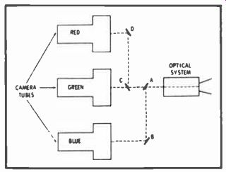
Fig. 1. Arrangement of basic components of a tricolor camera.
This varying sensitivity of the eye was considered when the luminance signal was designed: The color signals from the camera are combined in definite proportions to form the luminance signal: 59 percent of the total green signal, 30 percent of the total red signal, and 11 percent of the total blue signal.
We frequently call the luminance signal by the term, Y signal, and express its signal voltage as E. The equation for expressing the content of E, can be derived from the percentages given previously and is written as: E, = .59 Ea + .30 ER + . I 1 E (I ) where, Eo = the voltage of the green signal, ER = the voltage of the red signal, and the voltage of the blue signal.
The actual formation of a luminance signal can be understood by E =
…considering Fig. 2.
Assume the scene to be televised consists of a card having four vertical bars. These are, from left to right: white, red, green, and blue. We adjust the camera so that each of the color signals from the camera is one volt when the camera is focused on the white bar. As equation I states, the luminance, or Y signal, will also be one volt at this time. A monochrome receiver tuned to this signal would produce a bright white bar on its screen.
When the camera is shifted to scan the red bar, the red signal remains at one volt and the blue and green signals drop to zero. If ER and E,; in equation I are zero, E, must equal .30 volts. A monochrome receiver will produce a gray bar with this signal.
Scanning of the green bar will produce a green signal of one volt and, zero for the red and blue signals. The luminance or Y signal will have a value of .59 volts and will produce a very light gray bar on the monochrome receiver. Scanning of the blue bar will cause the blue signal to be one volt and the red and green signals to be zero. The Y signal will be 11 volts and the monochrome receiver will produce a dark gray bar.
The Chrominance Signal
In addition to the luminance signal which conveys the black -and white information, we must transmit a signal conveying the color information. This is called the chrominance signal and. since it conveys only color information, we must remove the black-and-white or luminance information from it. We can do this by subtracting the luminance voltage, E, from each of the three color signals produced by the color camera. Fig. 2 shows how this is done. The polarity of the luminance signal is inverted and combined with each of the three camera signals. The result is three signals representing red minus luminance, blue minus luminance, and green minus luminance. These are the important color-difference signals and are designated as: E E.
E. , and Ec E. . These are often shortened to R Y. B Y. and Ci Y; but it should be remembered that these represent voltages and not colors.
The term E, ' in each of the color difference signals has the value given in equation I. If we substitute this value, we obtain three equations for the color-difference signals in terms of the three primary colors.
E,t Er = E -E, = E -E, _ E ( .30 ER + .59 Ec+.I I E) ER.30 ER -
.59 E -.11 E
.70 E -.59Ec-.1I E (?)
Similarly
Ec-Ey _ .41 Ec- .30 E -. E (3)
E-Ey = .89 E-.59 E-.30 E (4)
A further understanding of these color-difference signal equations can be derived from Fig. 2. If the red bar is being scanned, the R-Y matrix receives one volt of red signal. The luminance signal is 0.30 volt at this time (from equation 1). The polarity inverter changes this value to -0.30 volt which is also applied to the R -Y matrix. The two voltages applied to the R -Y matrix form the R -Y signal: 1.0 volt minus 0.30 volt or 0.70 volt.
Note that this agrees with the coefficient of ER in equation 2.
The luminance signal is 0.59 volt when the green bar is being scanned and the red signal is at zero. The R -Y signal becomes 0.59 volt.
This agrees with the coefficient of E,; in equation 2. During the scanning of the blue bar, the signals to the R -Y matrix are zero and 11 volt; the resultant R -Y signal becomes -.11 volt. This is the coefficient of E in equation 2. The voltages of the color signals in equations 3 and 4 can be derived in a similar manner.
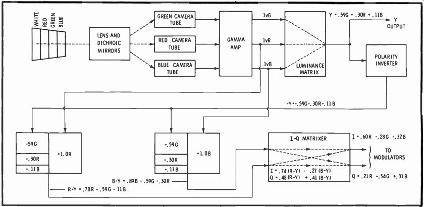
Fig. 2. Developing the luminance and color-difference signals in the transmitter.
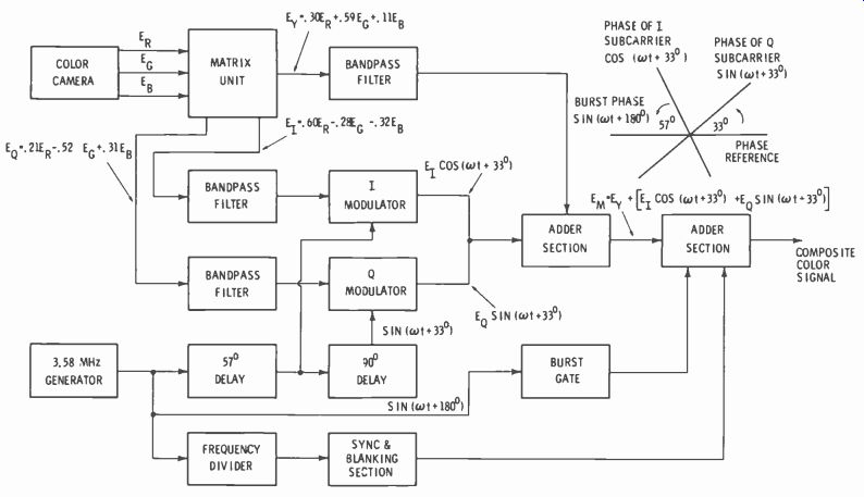
Fig. 3. Matrix unit in transmitter mixes three camera signals to form luminance,
I, and Q signals.
The voltages of the color-difference signals all become zero when the white bar is scanned and no chrominance signal is developed.
This is as it should be, because only a luminance signal is needed for black -and -white information. This is also true for any shade of gray.
Assume that the brightness of the white bar has been reduced to 50 percent. This means that the camera tube output signals would be reduced to .50 volt. If each coefficient in equation I is reduced by 50 percent, the luminance signal voltage would equal .15 + .295 + .055 or .50 volt; and the color-difference voltages would still be zero. The only signal would be the luminance signal representing the bar but its amplitude would be only 50 percent. The monochrome receiver would reproduce a gray bar halfway between white and black.
For the sake of economy, .the designers of our color -TV system decided that only two signals could be used to transmit the three color difference signals. It was found that a signal representative of E6 E, could be formed in a receiver by combining suitable proportions of E,1 -E, and E -E,-; therefore there was no need to transmit E6 -E. The proportions of -.51 (ER-Er) and -.19 (E,1-E,) will produce a signal equivalent to In the actual transmission of color, two signals are used to convey color information. These are the I and Q signals and they are formed by combining specific proportions of E,1 E, and E É,, as shown in Fig. 2. It was found that better reproduction of color could be obtained with this system.
By combining .74 (ER -Ed and -.27 (E,1-E, ). the I signal is formed.
The Q signal is composed of .48 (E11-E, ) and .4I (E,1-E,). If we subtract the value of E, (equation 1), we obtain E, and E, in terms of the three color camera signals.
E, = .60 E-.28 E6-.32 E,1(5)
E,t = .2I E,1-.52E6+.31 E,1(6)
The matrix unit in the transmitter forms the luminance, I and Q signals by mixing the three camera signals as can be seen in Fig. 3. The luminance signal passes through a bandpass filter and is fed into the adder section. The I and Q signals also pass through bandpass filters but then are fed to the modulators.
The I signal modulates a subcarrier with a phase of cos (1..t + 33°): the Q signal modulates a subcarrier with a phase of sin (,..t + 33°). The phase reference is the phase of the color burst plus 180°. The phase angles between the two sub carriers and between them and the color burst are also shown in Fig. 3.
The I subcarrier is leading the Q subcarrier by 90° and lags the color burst by 57°. A very close tolerance is required for these phase differences. This is accomplished by using a common source at 3.58 MHz for all signals including the synchronization.
The chrominance signal is formed by the outputs of the I and Q modulators. and is then merged with the luminance, sync. and blanking signals to form the composite color signal ready for transmission.
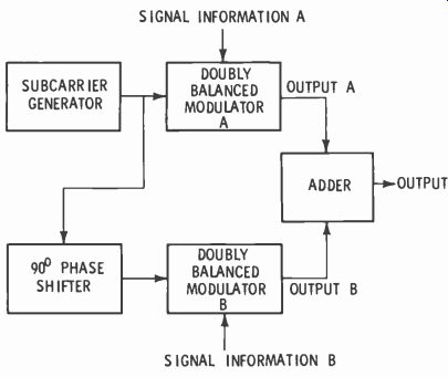
Fig. 4. Divided-carrier system modulates subcarrier with I and Q signals.
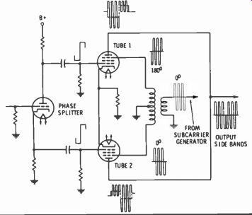
Fig. S. Doubly balanced modulator circuit used in divided-carrier system.
The Composite Color Signal
The original 4.25 -MHz bandwidth of the monochrome (luminance) signal had to be retained in the color TV system in order to meet the requirements of compatibility. The chrominance signal also had to be included within the allotted 6 -MHz channel. Meeting these requirements posed quite a problem to the system designers hut was accomplished by placing the chrominance signal at the proper place within the hand of video frequencies and by limitation of its bandwidth.
An interleaving process makes possible the inclusion of both the chrominance and luminance signals within a 425-Mtllz video hand. The energy of the luminance signal. as with any signal. concentrates at definite intervals in the frequency spectrum. Consider an amplitude modulated signal of 10 MHL The side hands of the signal would exist relatively close on either side of 10 Fig. MHz. There would be no energy existing between the upper sideband and the edge of the lower sideband of the second harmonic at 20 MHz.
It is in these blank areas that the chrominance signal energy is concentrated. There is no objectionable interference between the luminance and chrominance signals.
The luminance signal is transmitted by conventional amplitude modulation of the video carrier. The chrominance is transmitted by means of a subcarrier, the frequency of which was chosen to interleave properly with the luminance signal.
This subcarrier frequency (3.579545 MHz) is high in the video hand so that its sidebands. when they are limited in bandwidth, do not interfere with monochrome reproduction of the luminance signal.
The subcarrier is modulated by a process known as divided -carrier modulation since two different signals (I and Q) must be placed on the same subcarrier. Fig. 4 illustrates the basic principle of the system. A generator supplies the subcarrier frequency of 3.58 MHz which is applied to modulator A. The same signal is shifted in phase by 90° and applied to modulator B. The schematic in Fig. 5 represents either modulator. The modulating signal (I or Q) is split in phase and applied to the control 'grids of the two tubes. The subcarrier is also split in phase by the transformer and applied to the suppressor grids of the two tubes.
Tube No. 1 increases in conduction when the signal at its control grid goes positive and a subcarrier signal of increased amplitude is produced. Tube No. 2 receives a negative signal at the same time and its conduction and output signal decrease. On the next half cycle of the input signal, these conditions are reversed.
The plates of the two tubes are tied together so the waveforms shown at the plates cannot exist separately but are actually combined. The signals at the plates can be seen to be 180° out of phase, and the actual output sidebands will consist of a combination of the two plate signals. Because they are out of phase, a cancellation takes place, and the output amplitude becomes the difference in the amplitudes of the two signals. Additionally, the phase of the output is the phase of the largest signal.
A change in the amplitude of the input signal causes amplitude change of the output signal. If the phase of the input signal changes, the phase of the output signal will change 180°. The output signal therefore represents the input signal but in terms of the phase and amplitude of the subcarrier frequency.
Modulator B in Fig. 4 operates in an identical manner except that the subcarrier input is delayed by 90°. Thus, the output of modulator B is 90° from that of A. This can be either a lead or lag depending upon the polarities of the modulating signals.
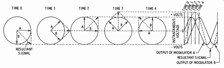
Fig. 6. Deriving a resultant waveform by use of vectors.
The output signals from the modulators are combined in the adder stage. Fig. 4, and become a single waveform varying in amplitude and phase in accordance with the amplitudes and phases of the I and Q signals. Two signals have been placed upon a single subcarrier and can be recovered by reversing the modulation process in the receiver.
So far, we have considered only simple, unchanging waveforms applied to the modulators. In actual practice, the waveforms are quite complex because the picture may be composed of many different hues and may be constantly changing as well. Consequently, it is necessary to consider the modulation characteristics in terms of vectors rather than in terms of sine waves. Referring to Fig. 6, we have two vectors which are displaced from each other by 90° just as the I and Q axes are separated by this amount in a color transmitter. The first pair of vectors are shown at zero time. The vector which represents the instantaneous value of A leads vector B by 90° (Vector motion is arbitrarily in the counterclockwise direction.) At this point in time, the value of A is zero while B is maximum negative. The resultant, or vector, sum of the two voltages is equal to the value of B. If we cause the vectors to rotate 45°, the magnitudes of A and B will be equal in value (70.7% of maximum) but opposite in polarity. In the sine wave diagram, the resultant is shown to be zero. At time 2, A is maximum positive while B has decreased to zero and the resultant is equal to A. We see that at time 3 the resultant has reached its positive maximum and both A and B are 70.7% of their maxima. At time 4, the value of the resultant is the same as it was at time 2, but the amplitudes of A and B have been interchanged. It is possible to show the value of the resultant for every value of A and B by simply performing the calculations for every degree of rotation of the two vectors. However, the above illustration should prove adequate for our purposes.
The voltages from modulators A and B of Fig. 4 arc combined in the adder to form a single waveform which varies in phase and amplitude in accordance with the amplitudes and phases of the two signals (I and Q axes) which produced it. Thus, the two modulating signals are able to modulate a single carrier in such a manner that both signals may be recovered separately in the receiver.
As we shall see later on, it is not even necessary that the demodulation be accomplished on the same axes as the ones on which the modulation was impressed. In fact, receivers in use today demodulate on I and Q. X and Z, RY and BY axes, and even on three axes (R Y. B Y, and G -Y). Video Spectrum The discoveries of Pierre Metz and Frank Gray were the key to the problem of inserting the color information into what seems to be the already-crowded 6 -MHz TV channel. Their studies of the scanning process used in telephotography and television proved that the energy in the video spectrum is concentrated at certain discrete points in the bandwidth. These points are situated at frequencies which are whole multiples of the scanning rate or frequency. The actual proof which they developed is far too complicated for inclusion in this series, but the following illustration should help to understand the principles involved.
It can be proven mathematically that any video signal is the combination of a number of pure sine waves which are multiples or harmonics of a fundamental frequency.
Thus, a video waveform consists of a series of sine waves all of which are multiples of the horizontal scanning frequency. There is a second series of frequencies to be considered, the vertical scanning frequency and its harmonics. This energy is concentrated in "sidebands" of each multiple of the horizontal scanning frequency.
From the foregoing, it is apparent that there is actually a considerable portion of the video spectrum of the TV channel which is not used in passing the monochrome information. Further analysis shows that these "holes" in the spectrum occur at the odd harmonics of one-half the horizontal scanning frequency.
The color subcarrier frequency was carefully chosen to occupy one of these "holes." In radio transmission and in monochrome TV, the modulation is recovered by a simple detection process. In color TV, however, the color subcarrier sidebands are made a part of the video modulation and must be processed further after video detection in order to recover the chroma information. Since the sidebands of the chroma subcarrier are a portion of the composite video signal, the frequency of the chroma subcarrier has to chosen not only for minimum degradation of the existing monochrome information but also so that it will not add undue interference to the picture. In addition, it must be chosen so that the chroma information which is modulated on it will not be outside the receiver bandpass.
By keeping the chroma subcarrier frequency as high as possible, the interference will be held to a minimum. In this manner, the reduced response near the upper limit of the video passband of most monochrome receivers will reduce the amplitude of the interference which reaches the picture tube, and the relatively tine "grain" produced by a high frequency is less objectionable. On the other hand, the subcarrier frequency must be low enough so that the upper sideband of the chroma information will pass through a color receiver.
Experimentation proves that it is not necessary for the pure chroma information to have frequency components which extend as high as the components of the monochrome signal. Stated another way. the R. B, and G signals do not require rise times which are as steep as the rise time of the Y signal. While luminance information must have frequency components above 3MHz to produce a pleasing picture, there will be no noticeable decrease in quality of a color picture if the upper limit of the chroma information is only 600kHz. Thus, the chroma subcarrier frequency should be approximately 3.6MHz if we consider that the practical video bandwidth for color transmitters and receivers is approximately 4.2MHz.
It has been shown that the signal energy which is produced by scanning an image is concentrated around the harmonics of the scanning frequencies. By the same reasoning, we find that the energy contained in the chroma subcarrier side-hands appears at frequencies which are the sum and difference of the subcarrier and the line and frame frequencies. Therefore, a frequency which is an odd multiple of one-half the horizontal frequency must be used for the chroma sub carrier so that the "interleaving" characteristic may be utilized. This subcarrier may be tentatively established by the following formula:
f_ 15750X455
3,583125Hz ,_ 2
This frequency was not adopted because of an objectionable feature which became apparent. Monochrome receivers which employ an intercarrier sound system develop a 4.5 -MHz signal at the output of the video detector. When this 4.5 -MHz signal heats with the color sub carrier, a difference frequency of approximately 900k Hz results and this produces an objectionable pattern on the screen. When the heat frequency is an odd multiple of one-half of the horizontal scanning frequency, it is least objectionable.
Since it would have been impractical to change the 4.5 -MHz intercarrier frequency, another method had to be found. This was done by changing very slightly the horizontal scanning frequency for color. This new scanning frequency was computed as follows:
f = 4' 281 6
15.734.264 Hz
Thus, the 286th harmonic of the new line frequency equals the 4.5 MHz intercarrier frequency.
Since each frame must consist of 525 lines, the color field frequency has been changed to 59,94 Hz.
Finally, the color subcarrier frequency becomes 3.579545 MHz.
The new scanning frequencies are slightly below those which were chosen for black -and -white transmission; however, the changes amount to less than 1%. These are within the tolerances that are allowed and do not affect the operation of black -and -white receivers when receiving a color signal. For the purpose of maintaining close synchronization of color receivers.
The tolerance for the subcarrier frequency is held to ±.00030. or about ± 10Hz; and the rate of change may not exceed 1 / 10Hz per second. The same percentage of tolerance also applies to the line and frame frequencies. and it is standard practice to develop all these frequencies from a common source.
Now let's see how all this theory works out on a real, live TV set.
Since the chroma signal falls within the bandpass of the video amplifier.
a dot pattern is actually produced on the screen of a receiver which is tuned to a colorcast. However, the interference is not visible because of a phenomenon known as "cancellation effect." This cancellation effect is actually nothing more than a way of taking advantage of a characteristic of the eve which has been known for a long time. The eye has the ability to actually integrate a series of visual signals and, consequently, it can detect a signal of very low intensity if it recurs at corresponding points in each of a group of adjacent traces on a scope.
This was discovered in radar technology where it was found that an observer could detect a target whose amplitude was actually less than the amplitude of the receiver background noise or "grass." Since it has been established that all of the sine wave components of the luminance signal are harmonics of the line and field frequencies.
These components may be considered to be in phase during successive lines or frames. Thus the signals on adjacent lines are additive and tend to reinforce each other.
The eye tends to integrate these successive signals and consequently it "sees" not individual lines and frames, hut a composite of a number of them.
Conversely, the interference signal. which is the result of the 3.579545 -MHz subcarrier, is applied to the picture tube in opposite polarity on adjacent scanning lines.
The eye tends to reject this signal because it averages the light produced by the spots, and, of course, the average of the alternate dark and light spots is zero.
Summary
In this first Section we have discussed the fundamental operation of the color camera and the method by which the three color signals from it are used to develop the luminance and chrominance signals.
These have to be transmitted separately so that a black -and -white receiver can receive a color signal.
The chrominance signals from the color camera are ultimately impressed on a subcarrier in such a manner that they may be recovered by the color receiver.
The chroma subcarrier sidebands can be transmitted in the same spectrum along with the luminance or Y information because the luminance signal energy is not evenly distributed in the spectrum, and so the two signals may be "interleaved" without interference.
To achieve compatibility, slight modifications had to be made in the horizontal and vertical scanning frequencies. but these are so slight that the normal tolerances of receivers will accept either scanning rates.