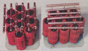
The photo below shows a pair of capacitor banks made using copper tubing for interconnects. One may use these banks in raw power sup plies and crossovers (with non-polarized caps, in this case). The sonics of such assemblies are better than with soldered lead tangles and PC boards, and are easy to build, install, remove, and wire.
DETAILS
Measure each capacitor and mark them for value and for polarity. Then cut the leads to the same length, and form loops in them using “chain nosed” or “round nosed” pliers. The loops should be a friction fit on the tubing.
Before cutting the tubing pieces to length, I sand the tubing stock and clean it with a solvent to achieve a bright, new surface for soldering. Then slide each cut tubing piece through the loops in the capacitor leads, and bond each row thus formed to the PC-board-material plat form with silicone and allow it to set.
Soldering requires a large iron be cause the tubing conducts heat easily, so you should solder all joints on one length of tubing at once, beginning at one end. The solder will follow the wire loop and make a very long, low-resistance joint.
Interconnecting the copper tubing depends on the series/parallel combination of capacitors needed. My preamp raw supply uses a pi-filter design with resistors bridging gaps between tubing runs. The power amp raw supplies use a bank of capacitors in parallel for each voltage. The assemblies in the photo became crossover components with capacitors in parallel.
It doesn’t take many sketches to design a neat, organized capacitor bank connected with copper tubing, which will perform superbly and look good in the process.