(This below article was begun early 2007, and most of its content is "modern" to that time. Here are more Notes on DACs, 2016 update)
In researching the best options to pursue for building my own Red Book-optimized digital-to-analog converter (DAC), I looked over several DACs on diyhifi.org, diyaudio.com and other forums/sites. I assessed both the topological (design) aspects as well as users' qualitative comments (i.e., whether it sounds good).
I have come to the conclusion that Peufeu's designs are probably the best-executed of the DIY DACs I have analyzed thus far, especially with respect to price vs. performance. So much so that in designing my own DAC, I will incorporate several of his ideas, albeit using a dedicated oversampling (OS) digital filter and, perhaps, PCM1704s or PCM1794 for the DAC ICs (as opposed to Philips TDA1545A).
Peufeu's designs are distributed among two sites: here is the original "Extremist" DAC, and here is the "What-the-F--k" (WTF) update. Some basic things that may be learned from Peufeu's notes are: Simply applying known-good DAC recipes will provide one with a very good starting base and with much potential (and also, very important: no wasted potential).
Some general tips are as follow:
DAC chip
Pick a well-respected DAC chip: Philips TDA1541A (double crown, if you can still find them) or TDA1545A (a decent, budget chip). If you've got some bucks, go for Burr-Brown/TI's PCM1704 (use it with TI's matching DF1704 oversampling digital filter).
After picking the DAC, proceed with PCB layout and overall design. Watch out for these common pitfalls:
- no ground plane
- no jitter-reduction plan
- no reclocking
- use of passive IV without doing distortion tests to check if the dac's output overloads or not
- real crummy printed-circuit-board (PCB) layout (see TentLabs White Paper on Supply decoupling and optimal DAC layout)
- sending high-speed digital signals through flying wires
- split ground plane like in Monica design below (split planes can help, but NOT THIS WAY)
- listening to DAC on a full-ranger (loudspeaker) from 1912 treated
with C37 lacquer and only playing Pierre Boulez on it.
Of the various techniques noted on Peufeu's site, master-clock injection is probably one of the most attractive. I have heard much about this approach in the past -- notably from "high-end" and professional manufacturers like dCS -- but never found a clear DIY way to implement the technique ... until now. Speaking of which…in Peufeu's block diagram of clock injection, note that before the clock cable (going to the transport), there is a pulse transformer on the DAC side only. Since this is sent BNC, one may ask if there any impedance-matching resistors needed (e.g. 75 Ω)? Yes, and use a 74HC04 buffer in the transport. Peufeu advises one to use pulse transformers and twisted-pair cable (RJ45), properly terminated.
DAC Power Supply and Regulation
Optimizing snubber values
- Snubber should probably not placed around each diode, but rather across the transformer secondary, which is better. Read this Hagtech article for more info.
- Snubber should be optimized for your specific transformer, diodes,
and supply caps.
Here is one approach:
- Build your power supply. Build it correctly. ie.: you see the T between rectifiers - capacitor - supply output, don't make that a T, run the trace through the capacitor pins, for instance.
- Then, place a snubber, with for instance a small capacitor (10-100 nF) + 100 ohm resistor.
- Load the PSU with a current sink, whatever
- Then place a 'scope on the snubber resistor, and observe the diode switch-off transient. Tune the resistor value until it's clean. - Values for snubber capacitor 10-100 nF and resistor 5-50 Ω... tune it. Depending on your diodes, you may not need it.
- Note: Snubber values depend on stuff that is hard to measure, like transformer inductance.
Use a shunt regulator for every important chip
Use ferrite chokes, not inductors
- Inductors will LC resonate with your supply caps. A good inductor has low Ω to dissipate low power. Chokes turn into resistors at HF, their purpose is to dissipate the HF energy while letting the DC through with no loss. Pick the cheapest ferrite choke in your supplier's inventory that has a rather highish resistance at above 1 MHz. Look at the datasheets curves, and be careful of max current, you don't want to saturate them, or they will just act like a piece of wire.
- Use SMD beads -- 1206 is really quite easy to solder. You need a fine tip soldering iron, and hair tweezers from your girlfriend's makeup kit. ($50 professional SMD tweezers are also a possibility...but supermarket stuff works just fine ;-).
Capacitors for decoupling and bypassing
- Put some Starget caps, use your favorite brand of good caps, with good behaviour at HF (switching power supply caps, for instance). On the digital chips, OSCON with 100nF ceramic SMD (like 1206 package) right on the pins is good. Make traces short.
Clocking and Digital Circuits
Clock Frequencies
Which clock frequencies should one choose? If you're injecting the clock back into the transport you will need to determine the frequency of the original player/transport clock. See this list for some examples.
Next, you need to choose the divisor to end up on the frequency you need, and that depends on the DAC chip; i.e. the sigma-delta types need higher clock freqs; for the multibit types it depends on the oversampling ratio, so one should choose a frequency that suits all the chips that one wants to try. So one will have to select one from the list found in the DAC chip's datasheet..
Buffering digital circuit (trace) lines
- For all resistors on internal digital signal lines, you can use 50Ω SMD (1206). For exporting the clock, check the ringing on the cable with a 10x probe and use the highest possible resistor to get a good signal.
- You may have seen the values of these digital-signal-line resistors vary from 50Ω up to 470Ω. Hagtech suggests also adding a 1uH in series with these resistors. So, what's up? Basically, for non timing-critical signals, you want to slow down the signal as much as possible to reduce RF emission and supply current spikes. But if you slow it down too much, it will not work anymore. So, it depends on the trace / cable capacitance etc. If you use specified impedance cable like coax or twisted pair, it makes sense to use the adapted source termination impedance. Inductors can ring with your cable capacitance so it is a dangerous game.
Master clock injection and SPDIF
- Use a pulse transformer on the clock line, with a ferrite core from the junk bin, and resistors adjusted for good signal shape... about 120-ohm. Get a real pulse transformer, or using one from a junked 100BaseT network adapter (then send your clock and SPDIF on a RJ45 cable, these have controlled impedance, much better than RCA jacks, good signal integrity, cost nothing, and twisted pair is good for transformer-coupled balanced signals like this). Plus, one connector means you won't connect the wrong one! It is better to use balanced signals (less problem with ground), that's why twisted pair is better.
- You may ask: RJ45 -- I thought true 75-ohm BNC was best? Also, "twisted pair"? Coax is good at RF when the grounds of everything are connected together, since the coax shield is connected to ground. However you will use transformers to AVOID connecting the noisy CD player ground to the DAC ground. If you use a coax in balanced mode, ie. connect it to a transformer without grounding the shield, the shield makes a *very* good antenna (since it is not grounded and carries half the signal!) So, for balanced, use twisted pair; for single-ended signals use coax. If you don't want to join your grounds, this means balanced, thus twisted pair. For instance if you connect two computers, say 20 m apart with STP cable (shielded twisted pair), the shield connects both grounds. Since computer cases are already grounded via the mains ground, you make a huge ground loop. This makes tiny sparks when you unplug! UTP (unshielded) cable does not connect the grounds : there are transformers in the ethernet adapters at both ends. So, I have never tested this, but I think it has potential: maybe RJ45, Cat6, or even SATA cable! (if it's good at sending 3 GBits/s, it won't care at 10 MHz...)
- Further question: This diyhifi.org message warned against twisted pair use. But the diff. between RJ45 twisted pair and that used in the DAC in the diyhifi post may be part of the misunderstanding. Answer: Yes. This guy takes a single-ended signal from a coax. He then runs it through a coaxial RCA connector of unspecified impedance, and through a twisted pair of unspecified impedance. You can bet sticking a network analyzer at the end of the cable would reveal a lot of reflected power and nice resonances from those impedance mismatches! If you use single-ended signals, then you must use coax all the way, with specified coax connectors, and proper termination! If you use balanced signals, then you must use twisted pair all the way, with specified connectors too, and proper termination! For the twisted pair, if the cable is shielded you can connect the shield to ground at one side. Not at both sides: this would make your transformers useless.
- Use a 74HC04 buffer in the transport to buffer all signals -- SPDIF or clock.
SPDIF vs. I2S
I would advise you to use SPDIF with no data (ie. silence) to send the
DAC master clock to the soundcard or to your transport. Why SPDIF, when
you could just use the clock on a cable? Sending the clock as SPDIF
has advantages:
- you can slave any soundcard to it without modifying the soundcard (for
this you could also use a wordclock but this needs a pro soundcard)
- it is independent of the dac's master clock frequency, so you don't
need to change the oscillator when your transport dies and you get a
new one.
However you need a PLL (w/VCXO) in the transport to reconstruct
a clock of the original transport's frequency (since the XTAL is removed).
The key is to put the CS8412/8414 in your DAC in slave mode (double
buffer). It receives the incoming SPDIF, but clocks the bits out with
the master clock you give to it. Obviously this will not work if the
clocks are not at the exact same frequency (it would skip or repeat samples).
But when the transport is slaved, no problem.
Output stage -- current-to-voltage (I/V)
- Use a Jocko Homo-type as shown here (circuit #8a). This one is really simple, you can add a DC servo by controlling one of the current sources. It costs almost nothing and sounds way better than op-amps.
- A JFET folded cascode may also work. But the above sounds a lot better. Idle current depends on your DAC... Make the IV a module so you can experiment.
Overall DAC design
Don't overdo it! Just remember -- continuous ground plane, sensible layout, decoupling, short paths...For more info, see this document from TentLabs.
Transport / CD Player Issues
The electro-mechanical unit that spins the disc and contains the laser and optical electronics is known as the transport. If you have a CD player, the DAC and the transport are in the same chassis. But, as you probably already know, you can use the player as a just a transport if you feed its data (via Digital Out) to an outboard DAC. Also, if you have the skill, you can incorporate a new DAC into the same player's chassis via I2S connection.
An often-neglected issue with Players and Transports is bit-accuracy. A possible solution to this is to plug the SPDIF output of the DAC-clock-slaved transport into a good PC soundcard (e.g. RME). Then feed the DAC from the soundcard's SPDIF output. So in the end you use the transport as a SPDIF encoder!
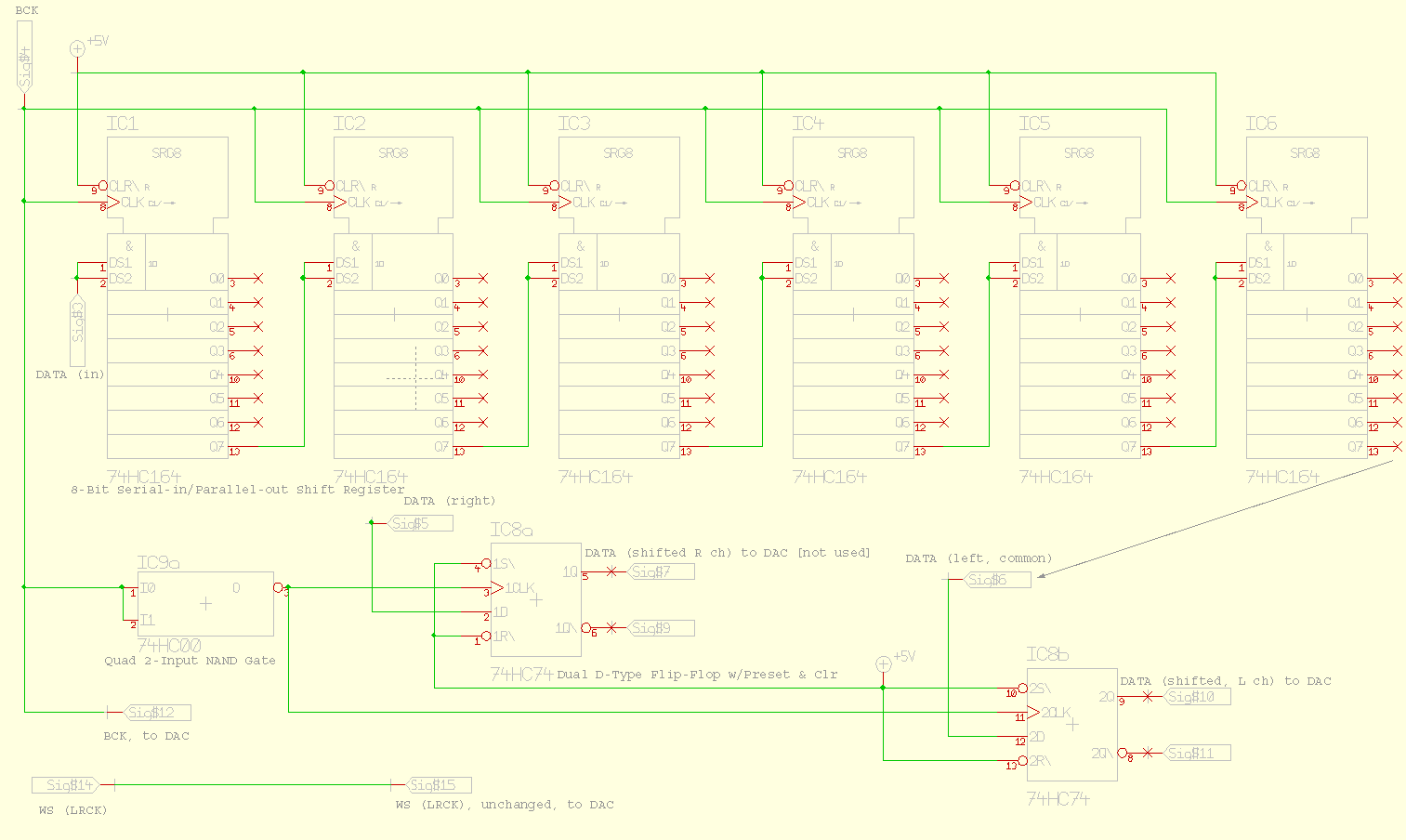
EIAJ-to-I2S converter (full instructions)
|
|||||||||||||||||||||||||||||||||||||||||||||||||||||||||||||||||||||||||||||||||||||||||||||||||||||
Timing diagram of I2S and EIAJ:

Relevant links:
EIAJ to I2S converter and vice versa (DIYAudio.com)
EIAJ to I2S (and vice versa) (DIYHifi.org)
Older ("legacy") stuff on this page...
Notes on non-oversampling DACs
Update: 2007-06-13
See comments in this diyhifi.org thread -- they pretty much summarize and conclude many of the issues discussed below.
Update: 2007-04-09:
After a few months of experimentation (and comparisons with DAC using other topologies) I've decided to give up on NOS DACs, in general, and diyparadise's Monica 2, in particular. [Please note: while this is generally a negative review of the Monica 2 DAC, it does not reflect my purchase experience -- both before- and after-sale -- with the proprietor(s) of diyparadise.com. That, in and of itself, was good.]
Here are discussion on various forums I've been engaged in on the issue (these discussions are partly what led me to the decision above):
Possible counter-arguments to my views on NOS DACs, in general, and diyparadise's Monica 2 in particular, may be:
Counter-argument: They (it) are (is) so inexpensive -- how can one go wrong at the price?
My "answers":
- There are many inexpensive components that also sound great. Take a late-model Toshiba CD/DVD player. Add $20-30 worth of tweaking parts and -- bingo! -- you've got a unit that sounds better than the NOS DAC noted above. [In all honesty, I personally haven't heard any NOS DAC other than the Monica 2. But I did some fairly extensive research beforehand -- i.e., read a lot of reviews and comments -- and, hence, decided to purchase the DAC. I.e., because it seemed to possibly be (TTBOMK) the best-rated DAC (for the price). Hence, no reason to purchase others.]
- Inexpensive parts and/or simple and easy-to-work with DIP DAC chip. The old Philips TDA series are "large", uncomplicated designs. They are easy to work with when compared to recent SOIC or SSOP package forms.
- Free technical "How-to" literature/plans on NOS DACs already avail. on the web. E.g. dddac.de. So original design/R&D/development costs are minimized.
Counter-argument: What about the generally-favorable reviews this DAC has received?
My "answer": I've wondered about these reviews and am puzzled? Couple of possibilities:
- If free samples are given to reviewers, it could influence "politics". Please note that this is mere speculation.
- Perhaps the reviewer(s) really hasn't (haven't) heard anything better? This sounds very unlikely.
- The "warm", "tube-like" sound of certain NOS DACs are simply an in-vogue trend-of-the-moment. People seem to always be looking for something new, something "interesting." But not something that's necessarily better or something they really need. A NOS DAC is something quite different from recent standard designs. And the sheer novelty of that fact, may to a large extent, drive the current popularity of this design. Some may recall the brief popularity single-bit MASH/Bitsream units enjoyed in the early 1990's. Much of this popularity was the result of Matsushita's and Philips' marketing hype.
BTW: I am still using the Monica 2 DAC in a portable application (see below (this page) and this link to a relative Head-Fi.org post). I'm in the process of portablizing an oversampling DAC, using a modern processor; a breadboarded version of which has already convinced me that its fidelity is many times superior to that of the Monica 2.
So what is my main at-home DAC or integrated disc-playback system?
For, SACD/DVD-Audio I use a self-modified Pioneer DV-59AVi CD/DVD-A/-V/SACD player. Some of the mods for this unit were similar to my Toshiba SD-3990 project.
For standard Red Book CD I use a self-modified Musical Fidelity A324 upsampling DAC.
I also modify and integrate separate components for portable-use systems. Here is one example of a recent project.
End of 2007-04-09 update.
Update 2007-01-03:
Below: Tentative cascode class-A JFET output stage for DAC, such as Monica. I will add to and update this schematic shortly. Also, to be added is a volume control option, for pre-amp applications.

Below: Monica2 non-oversampling DAC, from diyparadise.com, fitted into a Serpac Model 131 enclosure. Note: it appears as if there is no DAC -- a Philips TDA1545A -- installed in the 8-pin DIP socket. The DAC is there, under the DIP socket, but not visible in this overhead view. I'm experimenting with stacking (paralleling) DACs, ala DDDAC.de, and the shown arrangement allows one to "roll" DACs quickly and easily for audio-fidelity evaluation. Also note the two-way rocker switched (to be used for power) is not yet connected.

Below: Monica2, now enhanced (tweaked) with four Wima 0.1µF bypass capacitors and oscillation-dampening rope caulk covering the clock.


Acknowledging the need for better I/V for Monica2, I'm not sure if a vacuum-tube solution is ideal. This NOS DAC, in its native form, sounds "tubey" enough; Grounded Grid -- diyparadise.com's preferred I/V stage for Monica 2 -- may, IMO but admittedly w/o having listened to one, color sound too much (again, based on my specific tastes/experiences with solid-state vs. tube (see below)).
My current home system consists of -- among other components -- self-moded, all-tube and hybrid pre-amps and amps from Dynaco and avahifi.com (the FET-Valve line). Most of my listening is via headphones, using DIY (and mostly portable) solid-state units. After years of listening/experimentation with tube/solid-state/hybrid gear, I am now leaning towards pure solid-state for best audio reproduction. It is harder to get rid of all jitter than to filter it with some tubes "effectively" smearing the digital grain -- and audio detail/resolution ...i.e. fidelity -- out of the signal. It is true that digital sounds harsh when there is jitter. There are several approaches to lowering jitter, but realize that It is extremely difficult and/or expensive to get rid of all jitter.
As shown above, I have already "portablized" Monica2, using a Serpac 131 enclosure and am currently experimenting with a decent-sounding, op-amp-based solution, probably class-A biased. It should fit within the same enclosure.
BTW: as noted above, I've been experimenting with stacking TDA1545s, all w/o much success thus far. If anyone has done similar tests, and has had better luck, please share your experience.
Home | My
PC-based A/V System (circa March 2004) | My
Home A/V System (circa 2001)
Disclaimer/Disclosure:
There are affiliate ads and product links on this web site. I earn income by ad-link clicks (e.g. "Ads by Google") and product sales (e.g. Amazon). If you are genuinely motivated to click a link or purchase a linked product, by all means do so. However, please realize that I obviously have financial interests here and while I try to be objective and fair in product reviews and recommendations, some personal bias may leak through. Also realize that it takes dozens to hundreds of ad-link clicks and/or product sales to affect income generation on this site. So, as an individual, your support or non-support of affiliate-linked products or ads is only a drop in a large body of water.