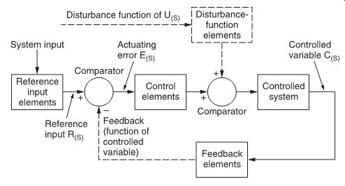
FIG. 1 Feedback control system: block diagram.
A feedback control circuit is one in which the value of a controlled variable signal is compared with a reference value. The difference between these two signals generates an actuating error signal which may then be applied to the control elements in the control system. This principle is shown in FIG. 1. The amplified actuating error signal is said to be fed back to the system, thus tending to reduce the difference. Supplementary power for signal amplification is available in such systems.
The two most common types of feedback control systems are regulators and servo circuits. Fundamentally, both systems are similar, but the choice of systems depends on the nature of reference inputs, the disturbance to which the control is subjected and the number of integrating elements in the control.
Regulators are designed primarily to maintain the controlled variable or system output very nearly equal to a desired value in the presence of output disturbances. Generally, a regulator does not contain any integrating elements. An example of a regulator is shown in FIG. 2, a stabilized power supply with series regulator.
The non-inverting input of a comparator is connected to a reference voltage (Vref), and a fraction of the output voltage Vout is fed back to the comparator's inverting input. The closed-loop gain G of this circuit is given by:
...and the output voltage by:
A servo circuit, on the other hand, is a feedback control system in which the controlled variable is mechanical, usually a displacement or a velocity. Ordinarily in a servo circuit, the reference input is the signal of primary importance; load disturbances, while they may be present, are of secondary importance.
Generally, one or more integrating elements are contained in the forward transfer function of the servo circuit.
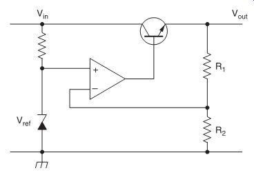
FIG. 2 A voltage regulator.
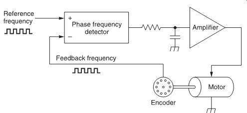
FIG. 3 Possible motor speed control servo circuit.
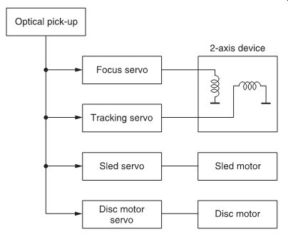
FIG. 4 Servo circuits in the CDP-101 compact disc player.
An example of a servo circuit is shown in FIG. 3, where a motor is driven at a constant speed. This circuit is a phase-locked system consisting of a phase-frequency detector, an amplifier with a filter, a motor and an encoder. The latter is a device which emits a number of pulses per revolution of the motor shaft. Therefore, the frequency of the encoder signal is directly proportional to the motor speed.
The objective of the system is to synchronize the feedback frequency with the reference frequency. This is done by comparing the two signals and correcting the motor velocity according to any difference in frequency or phase.
Summary of the servo circuits in a CD player
For this explanation, the Sony CDP-101 CD player is used as an example. It uses four distinct servo circuits, as shown in FIG. 4. These are:
1. Focus servo circuit: this servo circuit controls vertical movement of the two-axis device and guarantees that the focal point of the laser beam is precisely on the mirror surface of the compact disc.
2. Tracking servo circuit: this circuit controls the horizontal movement of the two-axis device and forces the laser beam to follow the tracks on the compact disc.
3. Sled servo circuit: this circuit drives the sled motor which moves the optical block across the compact disc.
4. Disc motor servo circuit: this circuit controls the speed of the disc motor, guaranteeing that the optical pick-up follows the compact disc track at a constant linear velocity.
The optical pick-up is the source of the feedback signals for all four servo circuits.
The focus servo circuit
Detection of the correct focal points
The reflected laser beam is directed to the main spot detector (FIG. 5a), an array of four photodiodes, labeled A, B, C and D. When the focus is OK, the beam falls equally on the four diodes, and the focus error signal, (A + C)--(B + D), is zero.
On the other hand, when the beam is out of focus (FIG. 5b, c), an error signal is generated, because the beam passes through a cylindrical lens, which makes the beam elliptic in shape (FIG. 6). The resultant focus error signal from the main spot detector, (A + C)--(B + D), is therefore not zero.
The focus search circuit
When a disc is first loaded in the player, the distance between the two-axis device and the disc is too large: the focus error signal is zero (as shown in FIG. 7a) and the focus servo circuit is inactive. Therefore, a focus search circuit is used which, after the disc is loaded, moves the two-axis device slowly closer to the disc.
Outputs of the four photodiodes are combined in a different way (i.e., A + B + C + D) to form a radio frequency (RF) signal, which represents the data bits read from the disc. When the RF signal exceeds a threshold level (FIG. 7b), the focus servo is enabled and now controls the two-axis device for a zero focus error signal.
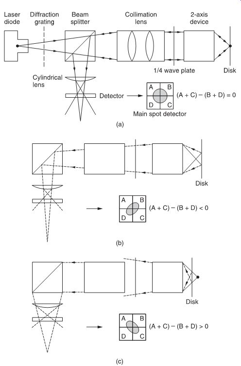
FIG. 5 Detection of correct focus (a) arrangement of optical pick-up:
focus is correct (b) and focus is not correct (c).
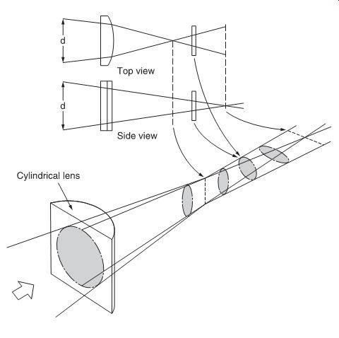
FIG. 6 How elliptical beams are produced by the cylindrical lens, when
the optical pick-up is out of focus.
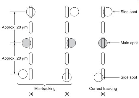
FIG. 8 Three possible tracking situations: (a, b) mis-tracking; (c) correct
tracking.
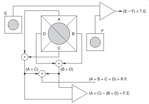
FIG. 9 How the various error signals are obtained from the photo-detectors
of the CD optical pick-up.
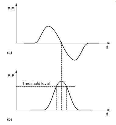
FIG. 7 Signals within the focus servo circuit.
(a) A focus error (FE) signal detects when the pick-up is in focus by means of combining the photo-detector outputs as (A + C) - (B + D): zero voltage means focus has been obtained.
(b) A radio frequency (RF) signal, obtained by combining the photo-detector outputs as (A + B + C + D), must exceed a threshold level before the focus servo is activated.
The tracking servo circuit
FIG. 8 shows the three possible tracking situations as the optical pick-up follows the disc track. In FIG. 8a and b, the main spot detector is not correctly tracked, and so one or other of the side spot detectors gives a large output signal as the pit is traversed. In FIG. 8c, on the other hand, the main spot detector is correctly tracked, and both side spot detectors give small output signals.
Side spot detectors consist of two photo-diodes (E and F) and generate a tracking error signal:
TE = E - F
The tracking servo acts in such a way that the tracking error signal is as small as possible, i.e., the main spot detector is exactly on the pits of the track. Tracking error, focus error and resultant focus signals are shown, derived from the optical pick-up's photodiode detectors, in FIG. 9.
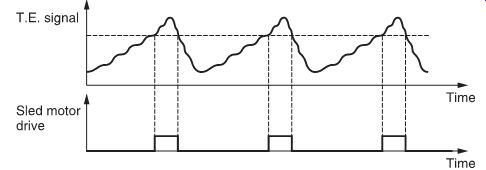
FIG. 10 Tracking error and sled motor drive signals within the CD player.
The sled servo motor
The two-axis device allows horizontal movement over a limited number of tracks, giving a measure of fine tracking control.
Another servo circuit, called the sled servo circuit, is used to move the complete optical unit across the disc for coarse tracking control. It uses the same tracking error signal as the tracking servo of the two-axis device. However, the output of the tracking servo circuit is linearly related to the tracking error signal, whereas the output of the sled servo circuit has a built-in hysteresis: Only when the TE signal exceeds a fixed threshold level does the sled servo drive the sled motor. Tracking error and sled motor drive signals are shown in FIG. 10.
The disc motor servo circuit
In Section 2, we saw how each frame of information on the disc starts with a sync word. One of the functions of the sync words is to control the disc motor.
The sync word frequency is compared against a fixed frequency (derived from a crystal oscillator) in a phase comparator and the motor is driven according to any frequency or phase difference.
As the length of the tracks increases linearly from the inner (lead in) track to the outer (lead-out) track, the number of frames per track increases in the same manner. This means that the frequency of the sync words also increases, which causes the motor speed to decrease, resulting in a constant linear velocity. The angular velocity typically decreases from 500 rpm (lead-in track) to 200 rpm (lead-out track).
As a practical example of the servo circuit ICs, the CXA1082 is one of the most used servo ICs. FIG. 11 presents a block diagram of a CXA1082.
This IC has two defined parts: a digital control part and an analog servo control part.
The TTL-I2 L registers are inputs/outputs to control the servo IC.
In this way the servo IC will be instructed by the system control.
Main inputs/outputs are to/from the system controller, which will trigger the execution of most operations. Besides these main instructions, there are a number of dedicated inputs/outputs, for specific functions.
The analog part consists mainly of the focus and the tracking control lines. Focus error and tracking error are input from the RF part of the CD player.
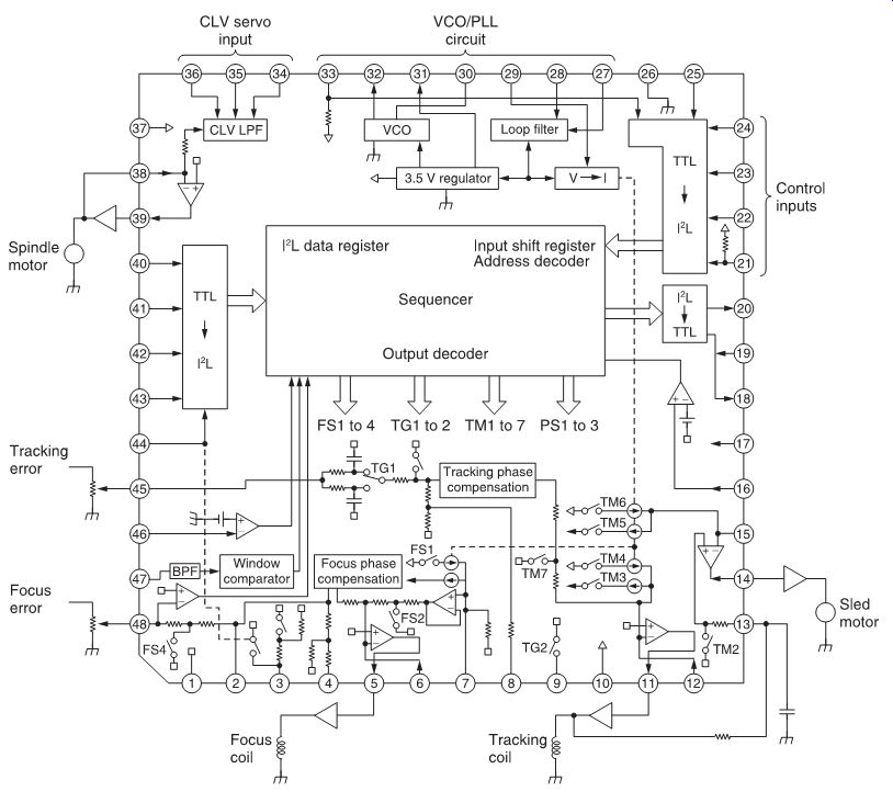
FIG. 11 CXA1082 block diagram.
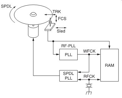
FIG. 12 Main servo circuits.
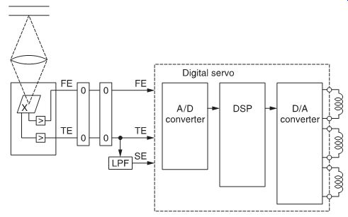
FIG. 13 Digital servo block diagram.
These signals will be phase-compensated to correct any error.
However, there are also a number of switches on these lines which are controlled by the sequencer. These switches enable manipulation of servo settings; in this way, gain can be set and power can be injected to drive the servo during specific operations; for example, if a track jump is requested, closing of TM3 and TM4 will inject the current to the tracking and sled coils for either direction.
The same circuits are used for initial control; thus, when the set is starting up it will try to focus the laser on the disc. In order to do this, the focus coil is driven up/down a number of times. At that moment the servo loop is disabled by FS4, and the up/down cycles are driven by FS1 and FS2.
Apart from these focus/tracking gain circuits, this IC also comprises a VCO/PLL circuit and part of the spindle servo circuit.
Digital servo
The latest development in servo circuitry is the use of digital servos. The benefits of digital servo circuits are listed below.
• Playability improved, as adjustments which used to be semi-fixed now become automatic and continuous.
• Adjustment-free; all adjustments are automatic, performed by the system itself.
• Use of digital signal processors (DSPs), which improves the possibilities and future features.
There are five servo circuits in a CD player: focus, tracking, sled, spindle and RF-PLL. Spindle and RF-PLL were digitized similar to drum motor/capstan motor circuits used in VCR and DAT sets. Focus, tracking and sled servos were digitized using DSP and D/A technology. FIG. 12 shows the main servo circuits.
Spindle and RF-PLL use input from a reference crystal (RFCK) and from the RF retrieved from the disc. Focus, tracking and sled servos use the A/D-DSP-D/A set-up shown here. FIG. 13 shows a block diagram of a digital servo.
• The A/D circuit will make 8-bit conversions of input signals at a rate of 88.2 kHz for focus and tracking error, and at a rate of 345 Hz for sled error.
• The DSP circuit will carry out (digital) phase compensation; detection of specific signals (focus OK, defect and mirror) is also carried out based upon the input signals. Also, similar to the analog servo circuits, if specific actions need to be taken, such as track jumps, etc. this can be implemented easily by the DSP stages.
• The D/A circuit will convert the error output signal to a 7-bit pulse width modulation (PWM) signal at 88.2 kHz for the focus and tracking coils, and a 7-bit PWM signal at 345 Hz for the sled motor. The PWM signals will of course be fed to operational amplifiers where they are converted to a correct analog driving signal for coils and motor.
The CXD-2501 digital servo IC block diagram in FIG. 14 shows the full integration of tracking, sled and focus servo into one IC.
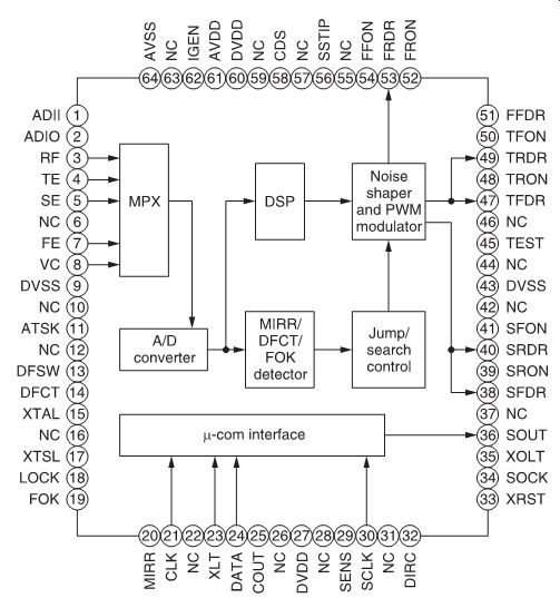
FIG. 14 CXD2501 block diagram.