David Tilbrook takes us stage by stage through the wonders of modern design techniques for low-level signals, as he develops an ultra-fi circuit for moving magnet (and moving coil) designs.
Just as a loudspeaker represents a non-linear load to the output stage of a power amplifier, a moving magnet or moving coil cartridge represents a non-linear source impedance to the input stage of a preamplifier. This is the cause of many of the problems associated with any preamp.
Both moving coil and moving magnet cartridges generate electrical signals through the interaction of a coil wire and a magnetic field. The signal voltage produced is therefore proportional to the relative velocity between the coil and the magnet assemblies. This relationship is predicted by Faraday's law of induction, expressed mathematically as:

... where Eta is the signal voltage at any instant and 0 is the magnetic flux.
The signal voltage produced at any instant is proportional to the rate of change of flux with respect to time, i.e:

The design of the cartridge must ensure that a linear relationship exists between the position of the stylus cantilever assembly and the magnetic flux. In this way changes in the position of the stylus give rise to changes in the magnetic field intensity. So the rate of change of stylus position with respect to time will be proportional to the signal voltage, ie:

... where Eta is the signal voltage and x is the stylus displacement from its equilibrium position. This means that the waveform actually 'on' the grooves is not proportional to the signal voltage itself. Instead it is proportional to the integral of the signal waveform. If a square wave, for example, is to be produced from a record, the waveform as seen in the groove with a microscope will be a triangle wave.
Since the signal voltage is proportional to the velocity of the stylus, the signal slope is proportional to the acceleration of the stylus. In order for the high signal slopes to be reproduced accurately by the cartridge it is important to realize that the cartridge cantilever assembly and its associated suspension and magnet/coil system form a resonant mass-spring system analogous to a complex electrical series resonant circuit.
Resonance At one particular frequency, called the resonant frequency, the impedance of the cartridge will no longer be related linearly to the driving force on the stylus, and distortion results.
To overcome this problem two techniques are used simultaneously.
First the resonant frequency of the cartridge is moved to a frequency below the audio spectrum. Using the damped mass -spring model of a magnetic cartridge we can predict that the resonant frequency of the cartridge is moved to a frequency below the audio spectrum. Using the damped mass-spring model of a magnetic cartridge we can predict that the resonant frequency will depend on the mass of the stylus cantilever assembly and on the 'springiness' of the cantilever's suspension.
This springiness is characterized by a number, often given the symbol k, called the spring constant. Spring constant is defined in terms of the force needed to bring about a certain compression or extension of the spring. Stiffer springs have a higher value for k. The spring constants, however, are so small that the numbers are hard to interpret. For this reason cartridge manufacturers usually specify this quantity by quoting the reciprocal of the spring constant, 1/k called compliance. Stiffer suspension systems have lower compliance figures.
As stated earlier, the cartridge resonant frequency is a function of both the mass and the compliance of the cantilever and suspension system. The damped resonance mass-spring model of a magnetic cartridge predicts that the resonant frequency will be given by the equation:
f= 1 /2 pi _/(mC)
... where m is the mass of the cantilever/stylus system and C is the compliance of the stylus suspension system.
Note that the equation for the resonant frequency of magnetic cartridges has exactly the same form as the equation for the resonant frequency of an electrical resonance circuit, ie:
f = 1/pi _/(LC)
... where C in this case is capacitance and L is inductance.
The equation predicts that the resonant frequency of the cartridge can be decreased by increasing either the mass or the compliance. Since the mass of the moving parts in the cartridge must be kept small so the stylus can respond quickly to changes in the record groove, the compliance must be increased until a suitably low resonant frequency is obtained. Most high-quality magnetic cartridges have resonant frequencies below 10 Hz.
The second technique used to overcome problems associated with this resonance characteristic is to decrease the Q of the system by damping the resonance with a suitable combination of mechanical and electrical losses. Mechanical damping is obtained by deliberately introduced friction within Ä the cantilever suspension system. The cantilever suspension is often terminated into a rubber mounting block for this purpose.
The electrical damping comes about as a direct consequence of the law of conservation of energy. The cartridge is acting as a generator, delivering power to the input resistance of the preamplifier. Since energy is absorbed by this load resistance the Q of the cartridge resonance is decreased.
Poles Apart
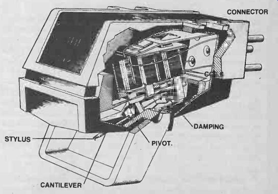
Until recently most stereo magnetic cartridges consisted of two fixed coils between the poles of a small magnet attached to the cantilever. Modulation of the record groove produces movement of the magnet, changing the magnetic flux and generating the signal voltage.
The coils usually have a large number of turns so that a reasonable signal voltage can be produced (typically in the order of 20 mV). The resistance of these coils usually ranges between 200-1000 ohms, but their impedance can be much higher, especially at high frequencies where the inductance of the coils becomes important. This type of cartridge is sometimes called a moving magnet cartridge to distinguish it from the more developed moving coil types. The relatively high reactive component of the cartridge impedance combined with the effects of the natural cartridge resonances makes it essential that the input impedance of the moving magnet (MM) input stage have well-defined characteristics if best performance is to be obtained from this type of cartridge. Most MM cartridges require a load impedance consisting of 47k of resistance shunted by several hundred picofarads. This capacitance is often provided by the shielded cable, but most cartridges require some additional capacitance across the MM input. In exceptional cases the input capacitance due to the shielded cable is too high.
In order to obtain the flattest frequency response possible from an MM cartridge it is essential that the load resistance be constant over the complete audio spectrum and beyond. For this reason measurements done on the input resistance of MM amps at one particular frequency (usually 1 kHz) are practically useless.
Fall From Grace?
Many input stages exhibit a characteristic of falling input resistance at high frequencies. The input resistance of a bipolar transistor, for example, even with a small amount of emitter current, is insufficient to ensure a constant resistive load to an MM cartridge. The common two or three transistor phono stages of a few years ago often suffered badly from this problem, degrading the top end performance of an otherwise good MM cartridge. The problem occurs because all bipolar transistors have decreasing gain at high frequencies.
The most common method used to increase the input impedance of a bipolar input stage is through the use of negative feedback. The decrease in gain of the individual transistors in the stage at high frequencies decreases the overall open loop gain of the stage, which in turn decreases the amount of negative feedback available. Furthermore, the negative feedback is often applied at the emitter of the first transistor.
The problem with this configuration is that the phase response in the negative feedback loop can easily be affected by the complex reactances of the cartridge and connecting cables, producing unwanted frequency response variations, or even instability in some cases.
All these problems come under the general heading of 'cartridge impedance interaction', and represent the most important single reason for the difference in sound between preamplifiers. Most preamps suffer from some degree of cartridge impedance interaction and in many cases the effects are pronounced.
In order to show how to overcome this major problem -and others -we will develop a full circuit design for an ultrahigh quality pickup input stage, both MM and MC, and discuss this design at each stage.
Action To Overcome
Overcoming cartridge impedance interaction can be achieved by separating the MM input stage into two active stages (see Fig. 1). The first stage consists of a single NE5534AN configured as a linear amplifier with a closed loop gain of around 8.3. The large amount of overall negative feedback increases the input impedance of the stage so that the measured input impedance is simply that of the 470k resistor, R2. Since the 5534 has a small signal bandwidth of around 10 MHz without additional compensation, the input impedance will remain unchanged over a very wide frequency range. The high input impedance of this stage would usually allow the input capacitor C2 to be conveniently small.
However, for best noise performance the value must be increased substantially. This is covered in detail later in this article.
Capacitor C2 is necessary since it is not advisable to allow DC current from the first stage to flow through the cartridge.
The value of C2 used here is 100uF, and this sets the lower -3 dB point well below 1 Hz. The upper-3 dB point of this stage is well above 100 kHz. An extended frequency response is necessary so that the accuracy of the RIAA equalization is not affected by frequency response variations that might otherwise occur in the first stage.
RIAA Equalization
We said earlier that the signal voltage produced by a magnetic cartridge is proportional to the velocity of the stylus.
If a low frequency signal is to be reproduced by a magnetic cartridge, large excursions of the stylus are necessary. If for example a 20 Hz square wave is to be reproduced by the cartridge then the cartridge must produce a DC voltage at its output for a period of 25 ms. In order to do this the stylus must move at a constant speed for this period of time, and therefore the waveform in the record groove is a triangle wave, as stated earlier.
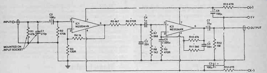
Fig. 1 Circuit of one channel of the moving magnet input stage.
Typical output voltages from moving magnet cartridges are in the order of 1 mV-2 mV for a stylus velocity of 1 cm/sec.
So if the peak voltage required on the square wave was, say, 10 mV, a stylus velocity of 10 cm/sec would be required for a medium sensitivity cartridge, so the stylus must move at a constant speed of 10 cm/sec for a 25 ms time interval. The stylus therefore moves a total distance of 2.5 mm! On a stereo record the channels are cut in opposite walls of the record groove. If a low frequency mono signal is to be produced, both sides of the record groove force the stylus away from its equilibrium position, and a large vertical stylus excursion results. In the case of our square wave, the vertical excursion would be roughly 3.5 mm, which is simply not possible. The record would-have to be as thick as most turntable platters! Two measures are used to overcome this problem. First, the two channels are recorded on the record 180° out of phase, so that the large vertical excursion is replaced by a large horizontal excursion. Second, the low end of the frequency response is attenuated before the recording process, so the stylus excursions are decreased. The specific amount of low frequency attenuation is defined as that which would be caused by a first-order high-pass filter with a time constant of 318 us ( ie the filter would be formed by an ideal resistor/capacitor filter, in which R x C = 318 us). To convert from these time constants into frequency, simply apply the equation:
1 f = 2t (t = time constant)
This equivalent to a 6 dB/octave filter with a-3 dB point at 500 Hz. To prevent the low end from rolling off indefinitely a second 6 dB/octave filter is used to flatten the response again at 3150 us or 50 Hz. After this equalization is applied, the stylus excursion of the 20 Hz square wave, for example, is decreased to around 0.3 mm, which is manageable.
Similar problems occur at very high frequencies. If we consider now a 20 kHz square wave at the same output voltage and hence the same recording velocity, the stylus now only moves a total distance of 2.5 um! Such minute distances are only a few orders of magnitude larger than the surface irregularities in the vinyl, so at these frequencies the signal-to-noise ratio is poor. To overcome this problem the top end is recorded at a higher level, which increases the stylus excursions and thereby improves the signal to noise ratio. The modifications to the recorded frequency response are referred to as RIAA pre-emphasis or equalization (RIAA stands for Recording Institute Association of America), and must be corrected for by the input stage. The RIAA playback equalization must boost the bass end and attenuate the treble end of the audio spectrum to return the overall frequency response to that of a linear system.
Down And Out
Since the low end is amplified most of all by the RIAA playback signal any turntable rumble or cartridge/turntable resonances will be amplified. Modern power amps are quite capable of delivering full power to a pair of loudspeakers at 10 Hz or below, so appreciable amounts of subsonic content can be fed to the loudspeaker. This is potentially dangerous to the bass driver and decreases the clarity and accuracy of the low end.
In an attempt to overcome this problem the RIAA has proposed a change to its playback equalization curve. The extreme bass frequencies are attenuated on playback by the addition of another time constant. This takes the form of a single-pole RC filter with a time constant of 7950 us, ie a -3 dB paint of 20 Hz. Since the frequency response is already flattened by the 3150 us time constant, this new time constant gives a 6 dB attenuation rate below about 20 Hz. The resulting RIAA playback equalization is shown in Fig. 2. Note that there are four time constants associated with the proposed RIAA equalization: 7950 us, 3150 us, 318 us and 75 us. These are shown on the Bode plot, which is the dotted line in Fig. 2. It should be emphasized, however, that the introduction of this low frequency time constant is not sufficient to remove severe cases of turntable or tonearm resonance. Some preamps incorporate multiple-order subsonic filters that offer a very fast roll-off below 20 Hz. The problem with this, however, is that severe cases of tonearm resonance or rumble generate distortion harmonics well above 20 Hz, into the audio spectrum. The only real cure is to remove the problem at the turntable or tonearm.
Many different techniques are used to give the preamp the desired equalization. The most common is to include the RIAA equalization circuitry into the feedback loop of the first stage.

Fig. 3 shows a very simple MM input stage of the general type often found
in medium priced amplifiers.
Transistor Q1 functions as a standard common emitter amplifier offering a voltage gain that is determined by the total impedance from its collector to earth divided by the total impedance from its emitter to earth. Transistor Q2 is a PNP transistor but functions in an identical manner. The product of their two voltage gains is called the open loop gain of the stage.
If a current path is now made available form the output of Q2 back to the emitter of Q1, the voltage gain will now drop to a new figure called the closed loop gain. This is negative feedback, and it has the effect of decreasing the distortion and increasing the input impedance of the stage.
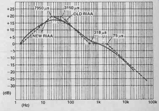
Fig. 2 Old and 'new' RIAA equalization curves (solid line). The individual
time constants (Bode plot -dotted lines) to produce the response are
also shown.
The RIAA equalization is introduced by applying the negative feedback via a network with a frequency dependent impedance. However, since this stage relies on the presence of negative feedback to ensure a satisfactorily high input impedance, the input impedance will vary as a function of frequency. The cartridge, however, must be loaded by a constant resistance if cartridge impedance interaction is to be avoided. Furthermore, since the negative feedback is coupled to the complex output impedance of the cartridge via the base -emitter junction of Q1, the negative feedback and hence the frequency response of the stage can be affected by the cartridge itself. As a result this type of stage can suffer badly from cartridge impedance interaction.
Several In
In the development of this design several input stage configurations were tested for noise, distortion and cartridge impedance interaction. When a medium-priced moving magnet cartridge was connected to a stage like that in Fig. 3, severe cartridge impedance interaction was evident. The frequency response of the preamplifier peaked above 2 dB at 13 kHz and rolled off rapidly above 15 kHz. The same cartridge when connected to our exhibited quite a good frequency response to beyond 20 kHz, and the frequency response graph obtained was identical to that when a FET buffer amp was placed between the cartridge and the input stage, indicating almost total lack of cartridge impedance interaction.
This is a result of the use of the separate linear gain stage formed by IC1 (Fig. 1) to isolate the cartridge from the RIAA equalization.
The preamp conforms to the proposed RIAA equalization in Fig. 2. The 75 us and 7950 us time constants are obtained by passive RC filters at the output of the first stage. Resistors R5,R6 and capacitor C3 form a simple 6 dB/octave low-pass filter with a -3 dB point at 2122 Hz, and
= 75 µs.
Capacitor C4, together with resistors R7 and R8, form a 6 dB/octave high-pass filter with a-3 dB point at 20 Hz, which is equivalent to a 7950 us time constant. The two remaining time constants are introduced into the negative feedback of IC2 and are formed by the values of resistors R9, R10, R11 and capacitor C6.
Fig. 3 Typical moving magnet input stage found in medium-priced amplifiers.
This method of generating the RIAA curve offers a number of advantages over the more conventional method.
Firstly there is low interaction between the different time constants, so that the RIAA curve can be optimized for a particular cartridge more easily by changing the resistor or capacitor values slightly. If the 75 us time constant is included in the negative feedback stage, the gain of the stage must decrease to unity at a suitably high frequency, so the stage must be compensated for unity gain to prevent instability. The NE5534AN is internally compensated for gains of 3 or above, so no additional compensation is required.
Stage Fright
Another advantage of the two-stage approach is that the total gain necessary in the MM stage can be divided between the two stages, so more negative feedback is available for each stage. This will have the effect of decreasing nonlinearities in the stages, provided the stages conform to the criteria for the avoidance of SID (slew-induced distortion) and amplitude overload. Fortunately, in the case of a phone input stage, both of these are limited by the recording medium. The RIAA standard sets a maximum recording velocity of 25 cm/sec, and most cartridges have output levels around the1 mV/cm/sec figure. So maximum output levels from such a cartridge will be put in the order of 20-30 mV. Even the highest output cartridge produces signal voltages usually in the 5 mV/cm/sec range. Combining a worst case of, say 5 mV/cm/sec with the maximum allowable recording velocity of 25 cm/sec yields an output voltage of 125 mV. To ensure that the input stage cannot be overloaded we simply set the gain of these stages so that this maximum input signal cannot drive the output of the input stages into clipping.
The NE5534AN is capable of driving to within 2 V of the supply voltage, so a supply voltage of ±15V gives the desired gain of around 75. We have divided this gain between the two input stages so that the first stage has a gain of 8.3 and the second stage a gain of 9 in the midband region (the actual gain of the second stage is of course a function of frequency due to the RIAA equalization).
As a result the total harmonic distortion of this MM input stage is well under 0.001%. The actual measured distortion using an HP3580A spectrum analyzer was around 0.0005% at 1 kHz. (At these distortion levels even the best distortion analyzers are practically useless, since the distortion is well below the level of noise.) Similarly, intermodulation distortion (IMD) was measured at well below the 0.0001% figure.
Noise
Another very important parameter for both MC and MM input stages is noise performance. Since an op-amp is used as the first stage of the MM input amp, we have only limited control over the noise performance of the stage. It is therefore essential that the op-amp used have excellent noise performance. In order to predict the necessary noise performance for a moving magnet input stage we must look at the sources of noise within the cartridge itself.
It can be shown from the laws of thermodynamics and statistical mechanics that every resistor generates noise. This noise is a result of the way nature works and is not caused by imperfection in a practical resistor (ie a perfect resistor will still generate thermal noise). This noise must be added to any signal dropped across the resistance. The equation for thermal noise is:
where
én = V(4kTRLf)
k = Boltzmann's constant
T = temperature in absolute units (K)
A= noise bandwidth (brickwall bandwidth)
R = resistance in ohms
en = average noise voltage
This equation predicts that thermal noise is raised by increasing resistance temperature or the bandwidth of the measuring equipment. So the frequency response of the apparatus. used to determine thermal noise must be quoted if the figure is to be meaningful. Furthermore, the4f here refers to a 'brickwall frequency response', not the usual half-power bandwidth, although for many purposes this is sufficiently accurate.
To overcome this problem noise performance is often quoted in the form of total equivalent input noise and expressed in units of
nV/_/hz (1 nV = 10^-9V).
This is justified by the equation for thermal noise, iei
So the ratio: since én = V(4kTRAfl then = (Vpfj(V(4kTR)) or én = V(4kTR). VAf
depends only on temperature and resistance, and this is just what we want. In order to get from this figure to an actual total equivalent noise figure we simply multiply by the square root of the bandwidth.
Most moving magnet cartridges have a coil resistance around 500 ohms. This resistance will generate thermal noise, so the cartridge itself limits the best possible signal-to-noise ratio.
Using the equation for thermal noise we obtain for the noise of the cartridge:
én =V(4 x 1.37 x 10-23 x 290 x 500) Hz
(assuming temperature of resistor is 290K).
i.e: én
= 2.8 x 10^-9 _/hz i.e: én = 2.8 nV/_/hz.
We can express this in more familiar terms by converting the cartridge noise figures into a signal-to-noise ratio figure. In audio we can regard the bandwidth in question to be around 20 kHz, ie \/Of = 140, and 140x2.8 nV/ V Hz = 392 nV.
If the average output level of the cartridge is around 5 mV, the signal-to-noise ratio is given by:
20 log 5x10^3 =82dB 392 x 10^-9
This figure represents the best signal-to-noise ratio possible with most moving magnet cartridges, since this is due to noise generated within the cartridge itself. A well-designed input stage should approach this noise figure as closely as possible without sacrificing performance in other equally important parameters such as distortion and frequency response.
The noise generated by an active device is determined by a number of factors, the most important of which is the current flowing through the device. However, since we have elected to use a high-quality operational amplifier for the input stage, we have no control over device current. All we can do is choose a low-noise op-amp and avoid degrading its noise figure as much as possible. The NE5534AN has a recommended equivalent input noise voltage around 4 nV/ \/Hz, only 3 dB above the noise generated by the cartridge itself! (n order not to degrade this figure we must keep all resistances in series with the cartridge as low as possible. Any additional resistance will generate a thermal noise voltage of its own, which must be added vectorally to that generated by the cartridge. From the basic equation of thermal noise generated by two individual resistors R1 and R2 for example, we obtain:
eñl = V(4kTR1z0 and = V(4kTR200
Here we assume that both resistances are at the same temperature. Since these noise voltages are not correlated (ie they consist of 'randomly' changing voltage) we add them using the vector sum: i.e: enT2 = en12 + en22 where enT2 is the square of the total equivalent noise voltage.
Therefore enT2 = 4kTAf(R1 + R2)
or enT
= V(4kTAf(R1 + R2)).
If R, now represents the cartridge resistance and R2 the value of an added resistance equal to the value of R,, we get
enT
= V(4kTAf(2R1)) = V2V(4kTOfR1)
or uni, = 1.4enT, equivalent to a 3 dB decrease in the signal-to-noise ratio.
Fig. 4 Standard technique for connecting an op-amp to a signal source.
Generation Game
Figure 4 shows the standard technique for connecting an op-amp to a signal generator such as a moving magnet cartridge. Most op-amps, and certainly the 5534, have input stages that consist of a differential pair, providing both inverting and non-inverting inputs.
The effective signal voltage generator of the cartridge is represented byes and the cartridge resistance by R5. Resistor 121 in this case would be 47k, so that the cartridge would have the correct load resistance. (The input impedance of the op-amp is very high and can be ignored for this discussion.)
Capacitor C1 prevents any DC current flowing through the cartridge from the non-inverting input. Since the combination of R1 and C1 forms a 6 d B/octave high-pass filter, the value of C1 would ordinarily be chosen so that the resulting-3 dB point was well below the audio spectrum, around 5 Hz for example. This will occur when the impedance of C1 is equal to that of R1, ie 47k. Since the reactance of the capacitor is given by the equation:
X, = 1/2 pi fC
we have: C 2 pi fX, In this case C -1 2 pi x5 x47x103 6.77 x 10^-7 Farads.
So to obtain an adequately flat frequency response a suitable value for C1 would be 680 nF (0.68uF), which is convenient.
When noise considerations are taken into account, however, this value is entirely unsuitable. The increasing impedance of C1 at low frequencies, while not sufficient to cause gross frequency response errors, will seriously degrade the noise performance of the stage. At sufficiently low frequencies the impedance seen by the non-inverting input will be simply the value of R1. Using the equation for thermal noise given earlier, we can calculate the resulting signal-to-noise ratio. Since éñ = V(4kTOfRi),
=V(4x1.37x10^-23x290x 20x 10^3 x 47 x 10^3) = 3.87µV, only 62 dB below 5 mV.
Furthermore, since the input stage is a noise generator, a low source impedance is necessary to minimize the resulting noise at the output of the op-amp. To overcome this problem we increase the value of Cl so that at worst its impedance at, say, 3 Hz is comparable to that of the cartridge ie.
C 2 pi x 3 x 500 10^6 x 10^-6F.
So a value around 100 uF should suffice. Notice that this capacitor would have to be an electrolytic or tantalum. Tantalum capacitors are not recommended, however, since their capacitance can be modulated by the input signal, producing considerable distortion at low frequencies.
The value of resistor R2 must also be low, so that the source impedance of the inverting input of the op-amp can be kept as low as possible. The limitation here is due to the minimum load impedance allowable on the output of the op-amp. Since the gain of the stage is given by the equation: A = R2+R3, R2 the ratio of R2 and R3 is determined by the desired voltage gain.
At the same time, however, the total resistance R2 + R3 represents the load on the output stage of the op-amp.
Since this must not be less than a certain specified resistance, determined by the individual op-amp used, a minimum value of R2 is predicated. In the input stage, for example, the required voltage gain in the first stage is around 8.3, so: R2+R3_ß3 R2 The NE5534AN has a measured minimum load impedance of 600 ohms, and for minimum distortion it is desirable to increase this slightly, for example to around 1k2. Therefore: 1k2 8.3 or R2
_ 144R R2
A suitable value for R2 would be 120 ohms, making R3 1 k0 to give the required voltage gain. Fortunately this value for R2 is low enough not to have significant effect on the noise performance.
Similar measures must be adopted around the second stage. At low frequencies the non-inverting input of IC2 (Fig.1)
has an input source resistance determined by R7 and R8, ie around 8k. The noise performance of the second stage would be improved if this value could be decreased. Unfortunately this would entail increasing the value of C4, which is not practical since this capacitor must be a green cap if the preamp is to conform accurately to the RIAA curve. This is not really a problem, however, since the voltage gain in the first stage increases the signal voltage at the input of IC2 to around 40 mV for 5 mV input signal, ensuring a sufficiently good signal-to-noise ratio in the second stage.
The Moving Coil Input Stage
The subject of noise performance is particularly important for a moving coil input stage. The moving coil cartridge works on exactly the same principle as the moving magnet. The signal voltages produced are the result of relative motion between a coil of wire and a magnetic flux. In this case, however, the magnet assembly is mounted rigidly to the cartridge body and the coils are mounted on the cantilever assembly; hence the name 'moving coil'. In order for the total mass and therefore the inertia of the stylus/cantilever system to be kept to a minimum, the coils are made with very fine wire and a small number of turns. Typical output voltages for moving coil cartridges vary widely from one manufacturer to another, but a figure of 40 uV/cm/sec is probably a reasonable compromise. A gain of 25 is therefore required to boost this voltage to that of a typical moving magnet cartridge. Once again we can calculate the best possible signal-to-noise ratio for a moving coil cartridge based on its thermal noise. The coil resistance of a moving coil cartridge with an output of 40 uV/cm/sec would be approximately 20 ohms (although this figure can vary widely, typically 5-50 ohms). From the equation for thermal noise we obtain: ie
_/hz
=V(4kTR.),
0n
_V(4 x 1.37 x 10-23 x 290 x 20)' _/hz
= 0.56 nV/_/hz.
The total noise over a 20 kHz noise bandwidth is therefore: I 0.56 nV x x/(20 x 10^3)
i.e: 0.56 nV x 140 _ 78 nV.
Since the cartridge output voltage will be around 40 uV/cm/sec x 5 cm/sec, ie 200 uV for a recording velocity of 5 cm/sec, the resulting signal-to-noise ratio will be: 201og 200 x 10-6 78 x 10^-9 or around 68 dB unweighted.
This figure is only approximate, of course, but it is roughly correct and represents the best possible signal-to-noise ratio with a moving coil cartridge. The object is to design a preamplifier that will approach this noise figure and maintain a flat frequency response, low distortion and constant resistive input impedance. At these noise levels we cannot use an NE5534AN in a circuit like the MM input stage. The total equivalent input noise in that case was around 4 nV/ \/Hz, ie 560 nV. The resulting signal-to-noise ratio would be only 51 dB with respect to an input signal of 200 uV.
In order to achieve a satisfactory noise performance it is necessary to look at the various sources of noise in bipolar transistors and decrease the total equivalent input noise through optimum biasing of the input stage and choice of the first transistor.
Noisy Thermals
One source of noise in the transistor is of course thermal noise. We saw before that to minimize thermal noise it was necessary to ensure a low source resistance over as broad a frequency range as possible. In order to do this for the MC stage the total resistance in series with the source must be kept to a similar value to the source resistance, ie around 10 or 20 ohms, depending on the cartridge.
The problem is that the resistance of the base-emitter junction of most bipolar transistors, called the base spreading resistance, is usually much higher than this. One solution is to use a large number of low-noise transistors in parallel to form the input transistor, thus decreasing the base spreading resistance.
Another solution is to use a power transistor, such as a 2N3055, as the input transistor, and the results using this method can be quite good! The third alternative and the one we elected to use in this design, is to make use of an exceptional matched pair produced by National Semiconductor. This device, the LM394, has a low base resistance, very low noise and high hFE of around 500. Another source of noise in bipolar transistors is shot noise or base current noise. This is a white noise "generator (ie the average amplitude of the noise current is constant with frequency), but the noise is increased if emitter current is increased. The base resistance, however, is also a function of the current flowing in the emitter, and is given roughly by the equation:
rb -26 (mA) -
The resistance of the base decreases with increasing emitter current, so noise voltage produced by thermal noise across the base resistance is decreased by increasing the emitter current.
In a bipolar transistor, therefore, we have two distinct sources of noise, one increasing with the emitter current while the other decreases. For this reason an optimum emitter current exists which represents the best compromise between these two noise sources. With an LM394 operated from source resistances typical of moving coil cartridges, the optimum emitter current is around 8 mA, much higher than would normally be used in an input stage. The result, however, is a very low value of input noise for source resistances around 10 ohms.
The complete circuit diagram for the moving input stage is shown in Fig. 5. The collectors of the LM394 are connected to the input of an NE5534, which functions as a high-gain differential amplifier providing adequate open loop gain to ensure low distortion and a flat frequency response when negative feedback is applied. The input choke is used to minimize the stage's susceptibility to RF noise.
The input impedance of the stage is determined by the parallel combination of R1 and R2, around 65 ohms for the values shown. This should be suitable for most moving coil cartridges, but is easily changed if required. The DC operating point of the LM394 is determined by the constant current source formed by Q1, Q2, R3 and R6. So the current in resistor R2 is determined by this constant current source and the DC current gain of the LM394. Hence the value of R2 can be increased, in order to increase the input impedance, over a fairly wide range of values without affecting the operation of the circuit.
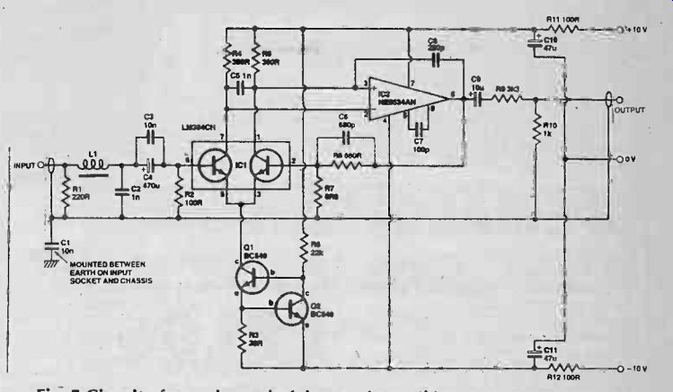
Fig. 5 Circuit of one channel of the moving coil input stage.
Silent Coupling
Once again the input coupling capacitor C4 is used to prevent DC current flowing through the cartridge. Capacitor C4 is IXP shunted by C3, a 10n capacitor, so that the base of the first transistor in the LM394 is decoupled for RF, through C2. Capacitor C2 represents a shunt capacitance to ensure correct loading of the moving coil cartridge. The value shown should be suitable for most cartridges, but can be changed for optimization with any particular cartridge.
To prevent loading the 5534A, the feedback resistor R8 is kept above 600R, ie 680R. Resistor R7 effectively increases with the cartridge and must be kept as low as possible for best noise performance. The value of 6R8 chosen gives the stage a gain of around 100, which is too high. This is corrected, however, by a simple passive voltage divider at the output, formed by R9 and R10. Capacitor C9 doubles as a feedback isolation capacitor to ensure that reactive components in the load cannot cause a phase shift sufficient to cause oscillation.
The noise performance of the stage is extremely good. The total equivalent input noise was measured at 83 nV over a 20 kHz noise bandwidth. This equivalent to 0.6 nV/_/hz or a signal-to-noise ratio of 68 dB with respect to an input signal voltage of 200 uV. This might sound like only an average noise figure compared to that attainable with the moving magnet preamp, but it should be remembered that the noise generated by the cartridge itself is of this order of magnitude! A final point worth mentioning here is that all the noise figures quoted in this article are flat or unweighted measurements!
------ Next month we put the theory into practice with a project based on these principles. Quite simply, it will be the best preamplifier input stage ever published.
= = = =
Electronics Today (UK print magazine)
Also see: MoCo Preamplifier (Moving-coil preamp)