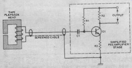
Fig. 1 Simplified details of a capacitively-coupled tape preamplifier input stage showing bias resistor, coupling capacitor and tape playback head.
Don Keighley discusses the advantages and disadvantages of capacitively-coupled and direct-coupled preamplifiers in tape playback systems. A new IC from National Semiconductor now gives the designer greater freedom of choice.
To most engineers, direct-coupling an audio tape playback head (cassette or reel-to-reel) to its playback preamplifier seems incongruous. Direct-coupling implies that there is a possibility of direct current flow through the head which will cause erasure of parts of the recorded signal--consequently most tape preamplifier designs have a capacitively-coupled input stage. An example of this is shown in Fig. 1.
The playback head in Fig. 1 is shown connected to the preamplifier by a length of screened cable (with the screen earthed): the input preamplifier stage is shown within the broken-lined box. Capacitor C1 prevents direct current flow from the preamplifier to the playback head which would otherwise occur via transistor-biasing resistor R1.
The value of this coupling capacitor depends primarily upon the input impedance of the preamplifier and can be calculated from the formula:
C1 = 1/[2 pi f0 R]
where f0 is the low-frequency corner frequency and R is the preamplifier input impedance (assumed to be purely resistive in this example). For a low-frequency corner of, say, 10 Hz and an input impedance of 50k, the capacitor value should be 320nF.
Now, if the preamplifier had a flat frequency response (ie equal gain at all frequencies in the audio band) this capacitor value could be OK. However, tape preamplifiers have an increased gain at low frequencies of about 25 dB (ie an 18 times increased response at low frequencies).
Input noise, which increases with low frequency anyway, thus causes high output noise levels after amplification.
Without resorting to the use of a less noisy preamplifier and tape head (both of which will be more expensive), the only other way of reducing this noise is to increase the value of the coupling capacitor. Increasing the capacitor, say, 200-fold (to about 64uF) will reduce output noise to an acceptable level.
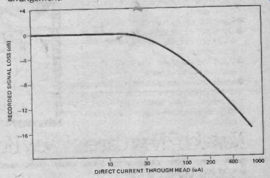
Fig. 2 Graph of approximate tape signal loss as a function of direct current
through the tape head during playback, for 100 plays. The pre-recorded signal
on the tape is a 10 kHz sine wave.
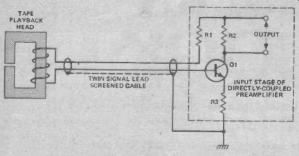
Fig. 3 Simplified details of a direct-coupled tape playback system. The transistor
bias resistor is now coupled to the transistor base via the playback head.
With a low bias current the DC voltage across the head is low (<1 mv) and
the input stage is virtually balanced.
Problems
The upper limit of the capacitor value is set by the turn-on time of the preamplifier--at the instant of switch-on this capacitor is fully discharged but must charge up to the preamplifier input voltage via the input impedance. If we assume that the input impedance is, as in the previous example, 50k, then it will take about two time-constants (a useful rule-of-thumb!) for the capacitor to charge up to about 90% of the final voltage.
Now 2 CR = 2 x64 x 10^-6x 50 000 = 6.4 seconds
In most applications this time is too long and so a trade-off between time and output noise must be made--not a satisfactory arrangement The most effective way to get a significant improvement in signal-to-noise ratio is, in fact, to direct-couple the playback head to the preamplifier. But this causes erasure of signal--or does it? Figure 2 shows a graph of direct head current against recorded signal loss, for a recorded signal frequency of 10 kHz which has been replayed 100 times. Severe signal loss does not occur unless the direct current through the playback head exceeds 30 uA or so. As long as this current is kept much lower, say an order of magnitude less than 30 uA, no signal loss will occur at all.
National Semiconductor has released a preamplifier IC (the LM1897) for use in such a tape playback system, which ensures that the direct current through the playback head is, typically, as low as 0.5 uA. A simplified circuit showing the IC's method of connection is given in Fig. 3. The quasi-balanced arrangement of the circuit means that screened cable with two twisted signal leads and an earthed screen can be used, thus decreasing capacitive hum pickup and crosstalk (from the other channel in a stereo system).
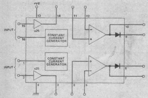
Fig. 4 Internal block diagram of the LM1897, showing leadout pin numbers.
An internal block diagram of the whole IC is shown in Fig. 4.
Constant current generators provide the bias current for the in put stages of the preamplifier (the input stages are shown as x 25 amplifiers) and they set the bias current for each amplifier to about 0.5 uA. Each input stage is followed by an operational amplifier, to allow equalization and further amplification (with the use of feedback networks) before the final output. The output signal is taken either via a diode (for diode switching applications) or straight from the operational amplifier.
IC specifications are good and include a power supply rejection of 105 dB; distortion figures of, typically, 0.03%; a wide gain bandwidth of 76 dB (5600 times) over a 0-20 kHz band width; and a power supply range of 4-18 V DC.
The circuit of a typical stereo tape playback system is shown in Fig. 5. Equalization is that of a standard audio cassette system for ferric cassette tapes (ie corner frequencies of 50 Hz and 1.3 kHz). Reducing R1 to 33k changes the upper corner frequency from 1.3 kHz to 2.3 kHz to give the required equalization for chromium dioxide tape. Circuit gain is 200 at a frequency of 1 kHz, but can be increased or decreased by reducing or increasing resistors R1 and R2 equally. Altering these two resistors equally will not affect the response of the circuit--just the overall gain.
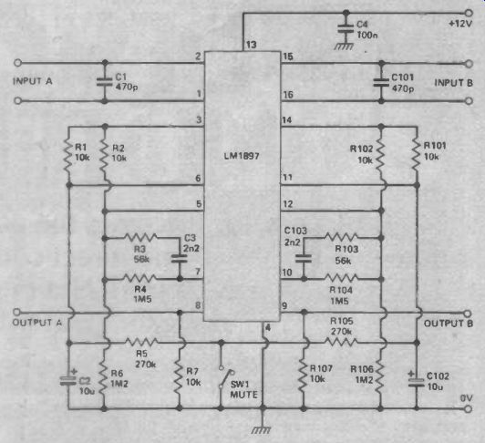
Fig. 5 Circuit of a typical stereo tape (ferric) playback system. To adjust
circuit equalization to suit chromium dioxide tape, see text.
Resistor R7, along with switch SW1, provides an optional muting facility. The value of this resistor should, at all times, be at least 10 x R1. In a stereo application the equivalent resistor of the other channel can be coupled to the same single-pole switch.
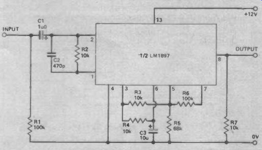
Fig. 6 A capacitively-coupled microphone preamplifier. The flat frequency
response of the circuit means that low-frequency noise is not such an important
consideration as in a tape playback system.
Other Responses
Of course, the IC can be used for applications other than tape playback systems. If we remember that the frequency response of the circuit is dependent on components in the operational amplifier's feedback loop, then it is a simple job to change the response. Figure 6, for example, shows the circuit for a microphone preamplifier which has a flat frequency response.
The circuit is capacitively-coupled to allow its use with a microphone, or other signal source, which is referred to ground--some sources cannot be directly coupled due to their nature.
Slower turn-on time and increased low-frequency noise are the consequences (although noise is not such an important consideration as it is in a tape playback system because of this circuit's flat response). Performance is still good and its low power consumption and supply voltage make the circuit ideal for battery operation.
= = = =