Extension of AM Servicing Methods. The serving of FM receivers conforms to the same basic procedures currently in use for AM sets but modified sufficiently to meet the differing characteristics of the FM receiver. A comparison of corresponding stages in both types of receivers shows that, except for the second detector and limiters (if any), there is no functional difference between them. Remember that we are concerned at the moment only with the function of each stage and not its design. From the serviceman's point of view, function is all-important and design is secondary. The serviceman, called upon to repair a set, is interested only in what each stage does in order that he may properly apply his servicing instruments.
The F.C.C. has assigned FM to the higher frequencies, 88 to 108 mhz.
When the serviceman, who has long been accustomed to working with receivers at the considerably lower AM broadcast frequencies, is confronted with an FM receiver, he will find himself considerably handicapped, unless he is familiar with the modified operation of radio components at frequencies of 100 mhz. Let us, therefore, examine the behavior of the most common radio components as the signal frequency rises to the region of 100 mhz.
Resistance: At the low frequencies, the resistance of a conductor is given by l R=p A …where …
R = resistance of wire, in ohms
p = specific resistivity
l = length of conductor
A = cross-sectional area of conductor
As the frequency of the current through the wire increases, it will be found that the resistance offered by the same length of wire will also increase. To understand the reason for the increase, let us consider what occurs within a length of wire when a current flows through it. It is known that current flow has associated with it a magnetic field or, what is the same thing in this instance, circular magnetic lines of flux. These are every where encircling the current. The definition of inductance depends upon these flux linkages and is expressed by the formula:
Inductance (henries) = [ Flux linkages encircling conductor / Current producing these linkages (m amps) ] x 10^-8
Consider now the end view of a small, round section of wire that has a current flowing through it (sec Fig. 13.1). Each small section of current flowing through the wire has magnetic lines of flux encircling it, but the sections of current at the outer edges of the wire have fewer lines of flux around them than the currents at the center of the wire. This is because the flux produced inside the wire by the central currents does not encircle the outer currents and hence does not influence their flow. The flux produced by. the currents flowing at the surface of the wire does, however, encircle the currents at the center and, consequently, exerts an influence upon them. From the definition just noted for inductance, it is seen that, since more flux link ages encircle the center of the wire, the inductance of the wire at the center will be greater than that at the surface. As the frequency of the currents increases, the inductance at the center of the wire offers more opposition (reactance) than the outer sections of the wire where there is less inductance.
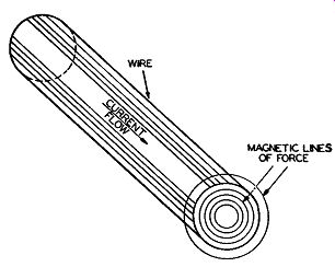
Fig. 13.1. Current flow through a wire and the magnetic lines of force
encircling the wire.
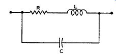
Fig. 13.2. The equivalent circuit of an ordinary resistor at the higher
frequencies.
Hence, the current, seeking the path of "least resistance," will tend to concentrate more at the surface (or skin) of the conductor as the frequency rises. This concentration has, in effect, reduced the useful cross-sectional area of the conductor. The resistance, due to this decrease in effective area, will rise, a phenomenon generally known as "skin effect." Another fact of interest to the serviceman is that, at the high frequencies, the equivalent circuit of so-called "pure" resistances becomes as shown in Fig. 13.2. The resistive and inductive effects of resistor are due, of course, to the previous explanation. The capacitance arises from the capacitance between the terminals and the capacitance between parts of the resistor itself.
Inductance: Inductance changes slightly from low to high frequencies, due again to the effect of the flux linkages and the currents. As the frequency goes up, the distribution of the currents in the wire will change and, because inductance depends upon this distribution, it too will change. The result is a slight decrease.
At low frequencies, those employed for AM sound broadcasting, the inductance of the tuning coils is comparatively high. Hence, a wire several inches long that might be used to connect the coil to a tube or capacitor would not add any significant amount of inductance. So long as the coil inductance is in the henry or millihenry range, no ordinary length of connecting wire will add sufficient inductance to alter the coil characteristics appreciably. When the signal frequencies reach 100 mhz, however, the inductance of the tuning coils approaches the point where even the small connecting link of wire can become important.
Note, then, that connecting wires become important at the higher frequencies, not because their inductance changes to any appreciable extent, but because the important components in the circuit become smaller. Even such things as the plates of capacitors introduce inductance into the circuit, and we find that trouble arises because of the interaction of the magnetic fields set up between ganged capacitors connecting to different circuits. It is common practice to shunt paper and electrolytic condensers with small mica capacitors in order to neutralize any inductance existing in these units.
Capacitance: The increased importance of stray capacitance in a high frequency circuit can be attributed to the same reasons as the importance of connecting wires. The stray capacitance does not increase, but rather the desired capacitance decreases, hence, assigning a more prominent role to any stray capacitance. In addition, there is leakage conductance which must be considered together with capacitance. Capacitors and insulators may, because of certain conditions, allow small amounts of currents to flow through them. They act then as high resistances, or poor conductors. The conductance is low and is labeled "leakage conductance." This has a direct influence on the type of insulating material which can be used successfully in high frequencies circuits, especially for tube sockets. Moisture and other atmospheric conditions may reduce considerably the effectiveness of these insulators at the higher frequencies and the result is poor operation of the set.
Trouble Shooting Procedures. The serviceman, when faced with the problem of trouble shooting or repairing an inoperative FM set, will find that all his experience gained from servicing AM receivers is applicable here, too. Thus, for example, signal tracing, starting from the speaker and working forward, is the best method of servicing an FM receiver just as it is for any AM circuit. In addition, despite the fact that an FM receiver is designed for the reception of FM signals, AM signal generators of the proper frequency range will serve for the signal tracing. The alignment procedures for the commercial models described earlier included alignment with an AM signal generator. If a set can be aligned with an AM signal generator, it most certainly can be tested with one.
Following recognized procedure, after the defect has been localized in a particular stage, voltage and-with the power off-resistance and continuity checks will lead the serviceman to the faulty component. The only real difficulty which the serviceman will encounter and one which is due to lack of experience is the localizing of defects in the R.F. stages at the front end of the set. Component failure, here, especially if one of the coils or other R.F. components are faulty, will prove especially troublesome. However, if the serviceman if familiar with the basic operation of high frequency circuits, as outlined in the preceding section, and uses all special instructions issued by the manufacturer, he should be able to surmount successfully any difficulties that may arise. At all times, in replacing components and/or connecting wires, duplicate exactly what has been taken out. It is a common practice among present-day servicemen to replace faulty components with whatever part happens to be on hand. Although this procedure may work in AM receivers, it will be less successful in FM sets. This is also true of television receivers, which function at the same approximate band of frequencies.
Preliminary Tests:
In receiving a set which is inoperative, there is seldom any reason for the serviceman to suspect that the tuned circuits are out of alignment. The more complicated receivers become-and the trend is in that direction-the less likely it is that someone owning a receiver will venture to meddle with it to the extent of adjusting the circuit alignments.
Possibly the only meddling that is done nowadays is to remove the tubes to have them tested at a near-by radio store. Here, the possibility of improper replacement is quite likely and it may save the serviceman hours of work if he first checks the tubes and the sockets they are in.
As a routine measure, the serviceman should check all tubes in the set.
Tube failure is one of the major reasons for sets becoming inoperative. It is also one of the easiest checks to make.
Many, if not all, of the present FM receivers are combination AM and FM sets. This gives the serviceman another means of localizing trouble in the receiver. If it is found, for example, that the set is perfectly normal on the AM bands, but inoperative when the switch is turned to FM, then the trouble must be contained in some part of the receiver which is exclusively used for the FM. It indicates, for example, that the audio amplifiers and the power supply may be eliminated immediately. Again, since most sets (for the sake of economy and compactness) have but one set of I.F. amplifiers, the chances are good that these are also in working order. It may be, of course, that one of the FM-I.F. coils is shorted, but this is not a common occurrence and may, at first, be discounted. Thus, through the simple process of testing the set on AM, we have eliminated anywhere from four to six tubes and as many stages. A glance at the circuit diagram of the set will show which circuits are common to both signals and which are not.
Combination receivers are becoming increasingly numerous because of the many popular types of services available. The additional circuits may make the overall circuit more complex and yet, on the other hand, they can make the task of trouble shooting easier. A common defect will show up in all circuits; a special defect will be confined to one particular path.
Phonograph attachments are common in modern FM receivers. These phonographs generally feed through the entire audio section of the set. As a simple test of the audio system, the serviceman has only to touch the phono graph needle and note whether any sound is heard from the loudspeaker.
Visual Check. An important step in the servicing of any electronic circuit is a careful visual inspection of the unit. Do this first with the power off and, if nothing wrong is found, with the power on. Here are some of the things to look for:
1. Are all the tubes lit or is one or more unlit? If all are unlit, then a fuse may be blown or the various filaments may be connected in series and one set of filaments is open.
2. Are there any charred components, particularly resistors?
3. With the power on, do any of the components overheat or smoke?
4. What effect does rotation of the various front panel controls have (with the power on)?
5. If printed circuitry is employed, are there any visible breaks in the wiring? These are but a few of the questions that a serviceman might ask him self as he visually examines a receiver. Additional questions will undoubtedly suggest themselves. Make as thorough an investigation as you can; you will find that it will frequently assist you materially.
General Servicing Procedure. For the purposes of testing a receiver to determine the cause and location of any defect, it is helpful to divide the set roughly into the following six categories:
1. Power supply.
2. Audio amplifiers.
3. FM detector or discriminator.
4. I.F. system
5. H.F. oscillator and mixer.
6. R.F. section of receiver.
The foregoing classification is true for all superheterodyne receivers.
Since no TRF types of commercial FM sets are being manufactured at present, the analysis will apply to all receivers that the serviceman is called on to repair.
Power Supply: Trouble in the power supply produces either a completely inoperative set or else low volume in the receiver output. Under these conditions, the first place to test is the B+ terminal of the power supply. A partial short-circuit in any portion of the receiver may result in an excessive current drain on the power supply and lower the B+ voltage considerably.
The audio output becomes weak and distorted. A total short-circuit will burn out the rectifier tube and cause any protective fuses to blow. Never replace a blown fuse until the cause of the damage has been determined. A hoarse, raspy audio output is another indication of trouble in the power sup ply, this time a faulty, electrolytic filter capacitor. This should not be con fused with a scratchy output, which is a result of an incorrectly centered speaker cone.
Audio Amplifier System: The simplest and most rapid method of testing the audio amplifiers is by applying an audio signal and noting whether an output is obtained. With the same strength signal, the output should be come louder as the test voltage is moved back away from the speaker. The output will be loudest when the signal is applied to the grid of the first audio amplifier. A more sensitive indicator is an output meter connected across the voice coil leads.
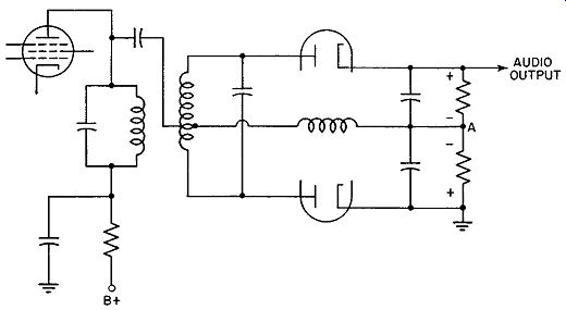
Fig. 13.3. A Foster-Seeley FM discriminator.
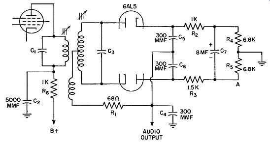
Fig. 13.4. A balanced ratio detector.
FM Detector or Discriminator: The various types of commercial FM detectors currently in use were analyzed in Section 9. To trace an AM signal through the detector, we must connect the indicator (a voltmeter or ammeter) in such a way that response to an AM signal is possible. In the diagram of a Foster-Seeley discriminator, Fig. 13.3, connection of the meter across either load resistor will result in a deflection if the AM signal voltage is being passed through the circuit. Each half of the discriminator is responsive to AM and, when the circuit is functioning properly, the d-c volt meter connected across either resistor will show a reading. It is usually most convenient to connect one end of the voltmeter to ground and the other end to the junction of the two load resistors, such as point A, Fig. 13.3. The ground terminal of the signal generator is connected to the receiver chassis. The output lead is connected through a 0.05-mf capacitor to the plate or grid of the preceding limiter. If the frequency of the signal is varied, by rotating the knob of the signal generator, the meter deflections will increase and decrease.
The linearity of the detector to FM signals can be determined by connecting the voltmeter across both load resistors and observing whether equal ( and opposite polarity) deflections are obtained for frequencies located equal distances above and below the I.F. mid-value. The linear response should extend ±75 khz from this I.F. point.
In the ratio detector, reproduced in Fig. 13.4, the voltmeter is connected between the point marked A and ground. Since point A is negative, the negative lead of the d-c voltmeter is placed here. The signal generator is then attached between the grid and ground of the last I.F. amplifier. If the circuit is operating normally, the meter will show a deflection. As the amplitude of the signal is slowly varied, the voltmeter will follow the changes in step. In addition, if the signal generator is set at the mid I.F. value and then varied from 75 khz below this point to 75 khz above, the indicator will show only a small change. This is true, providing the circuit is correctly aligned and the voltage output of the signal generator does not change with frequency. If either diode is inoperative, there will be no meter deflection.
It is well to remember that if the secondary of the FM detector (or discriminator) is detuned, distortion will result. If the primary is detuned, the signal output will be weakened, usually accompanied by some distortion, also.
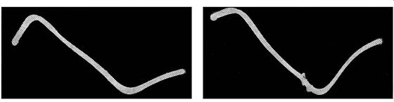
FIG. 13.5A. Secondary tuning core adjustment of discriminator transformer
improperly set.
Fig. 13.5B. Primary tuning core adjustment of discriminator transformer improperly set.
FM Detector Checking with Sweep Generator. For those service shops that possess sweep generators, the FM detector may be checked by observing its response or S-curve. Connect a sweep signal generator to the grid of the tube preceding the FM detector. Set it to sweep 450 khz above and below the I.F. Connect an oscilloscope across the output terminals of the detector. The appearance of the S-curve on the oscilloscope screen will tell the complete story concerning the operating condition of the detector.
When the transformer coupling network connecting the FM detector to the previous stage is not properly tuned or centered, the S-curve will appear either as shown in Fig. 13.5A or B. In either case, the sound output will be distorted. To correct this condition, adjust the iron cores of the FM detector primary and secondary windings. The primary controls the linearity of the S-curve, and the secondary adjustment governs the centering of the S-curve.
Another defect made evident by the S-curve occurs when the bandwidth of the tuning circuit is too narrow. (See Fig. 13.6.) When this happens, the output becomes distorted when the incoming signal is fully modulated. The sounds become "hissy" or "raspy." The solution for this, assuming that the circuits were not originally designed this way, is to realign them.
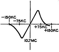
Fig. 13.6. Bandpass of discriminator too narrow.
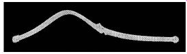
Fig. 13.7.
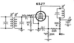
Fig. 13.8. If "R" should open up, the limiter may become noisy
with moderate signals.
Whenever the complete response curves are viewed on the oscilloscope screen, marker signals obtained from a separate AM signal generator should be used to identify the mid I.F. and the end frequencies of the linear section of the curve.
In the Foster-Seeley discriminator the two diodes should be matched fairly closely. If one discriminator diode has low emission, the S-shaped curve will now assume the appearance shown in Fig. 13.7. This condition results in poor noise rejection at low signal inputs and sound distortion at high signal inputs. When both discriminator diodes have low emission, the sensitivity of the receiver is poor.
Checking Limiters. When a receiver that has been operating normally suddenly becomes noisy, the discriminator tubes and alignment should be checked. If the receiver contains a limiter stage, this too should be checked. Limiters become noisy when their grid-leak circuits open, or the voltages applied to the electrodes rise above normal. In many circuits, the low voltages for the screen and plate are obtained by the voltage divider arrangement shown in Fig. 13.8. If R should open, the voltage applied to the screen will rise. Under these conditions it will require considerably stronger signals to bring the tube to saturation, and the limiting action of the tube is impaired. Ordinarily, most limiter tubes will saturate with signal voltages of 2 volts or more. The best method of testing the limiter is to measure its grid, screen, and plate voltages and compare the values obtained with those specified by the manufacturer.
A noisy ratio detector can usually be traced to an open electrolytic capacitor. This capacitor, together with its shunting resistor, stabilizes the ratio detector against amplitude modulation of the received carrier. If the capacitor becomes defective, noise will ride through and be heard. The serviceman will find that sets using the ratio detector will receive weaker signals with less background noise than the same signal in a set possessing the Foster-Seeley discriminator. In the latter receiver, noise disappears only when the preceding limiter is driven to saturation, but no such "threshold" effect is apparent in the ratio detector. However, in all instances, when the noise or interference is stronger than the signal, the noise will prevail.
I.F. System: The placement of the indicator when the I.F. system is tested will depend upon the type of FM detector used. For the conventional discriminator, which has one or two limiters preceding it, it is possible to place the indicating meter in the grid circuit of the last limiter, if there are two, and test the I.F. system. The signal generator is connected to the grid of the mixer tube, and the frequency of the signal set at the I.F. If all the intervening stages between the mixer and the limiter (where the meter is located) are in proper operating condition, the meter will deflect. If no indication is obtained, the signal generator will have to be brought back to the grid of the first tube preceding the limiter. In this way, only one stage is under test. If the meter deflects, indicating that the stage under test is functioning properly, the generator is moved back one stage and the signal applied again. In this manner, we gradually work back to the point where the trouble exists in the I.F. system. However, as a preliminary test, the signal is fed through the entire I.F. system, since if no trouble exists in this portion of the receiver, valuable time is not spent testing each stage.
While testing the I.F. system, it is possible also to determine whether the circuits are in alignment. Maximum deflection of the meter should be obtained when the test signal is at the I.F. value. Shifting the frequency an equal number of kilocycles above and below this point should produce equal readings on the meter.
Note that the foregoing procedure is followed only for FM sets employing conventional discriminators with their attendant limiters. In receivers possessing the ratio detector and in which no limiter is employed, the volt meter is connected to the point where the A.V.C. voltage is obtained from the detector. The positive lead of the meter is attached to the chassis. Any signal fed into a properly operating I.F. system will result in a voltage at this point in the detector.
The I.F. system of present FM sets is generally a combination of AM and FM transformers with a single tube for each stage serving both AM and FM. With the exception of the I.F. switch and the FM, I.F. transformers, parts giving normal indications on AM will test normal on FM. Hence, if the I.F. system is found to be in operating condition on AM but not on FM, it would be best to check these particular components first.
R.F. Section: To test the R.F. stages of the receiver, we still retain the AM signal generator, provided its range extends to the necessary frequencies. ,Again, as before, the position of the indicating meter will depend upon the type of FM detector in the circuit. The explanation given above will apply equally here. For the signal tests, use an R.F. signal generator with an amplitude-modulated output. The ground lead of the signal generator is connected to the chassis ground; the output lead is connected through a 0.05 mf-capacitor to each of the test points, as explained below.
The input of the R.F. section of the receiver consists of an R.F. amplifier, a mixer, and an oscillator. In some sets, no R.F. stage is included; in others, such a stage is employed only for the FM signals.
In the testing of an FM receiver, the input circuits are tested last.
Hence, if the foregoing step-by-step procedure has indicated that all of the other sections of the receiver are functioning properly, then, in the testing of the R.F. circuits, it is best to start at the oscillator. The reason is that the oscillator is the one stage, in the front end of the receiver, which is most critical in operation and most likely to be at fault. By measuring the voltage between the control grid and cathode of the oscillator, we can determine whether the stage is functioning. Measure this voltage with a high-resistance voltmeter, otherwise the value read can be misleading. The voltage at the control grid (with respect to the cathode) may have any value between -2 volts and -10 volts. Consult the service manual issued by the manufacturer for the proper value. Too low a value may be due to a bad tube or lowered operating potentials. Measure the plate and screen voltages and, if these are within the correct range, change the tube. The oscillator grid voltage should be measured on all bands since it is very possible that the oscillator will function on some frequencies and not on others. Reasons for this may be a defect in the switching system or the plain fact that a tube will oscillate readily at the low frequencies and yet fail to do so at the higher frequencies.
If the oscillator is operating satisfactorily, place the signal generator at the signal grid of the mixer tube. Adjust the front dial of the receiver and the signal generator for the same frequency setting. If the set, at this point, is operating satisfactorily, the indicator should show a deflection. If no response is obtained, change mixer or converter tubes, measure voltages at the electrodes and/or make resistance checks to locate the defective component.
Once the defect has been traced to a single stage, a routine analysis will, in almost all instances, reveal the trouble.
In probing around the underside of the chassis, the serviceman must be careful not to rearrange any components--especially small coils. It is impossible to emphasize too strongly the criticalness of these high frequency circuits, a fact which is usually fully appreciated only after such a circuit has been built or rearranged and it becomes inoperative. Many of these circuits, especially the oscillator, contain compensating capacitors. Their purpose is to compensate for changes in the electrical characteristics of other capacitors and/or the coils. If one of these special capacitors becomes defective, i.e., open, the circuit is detuned. If the serviceman is unaware of this situation, he may conclude that the circuits merely require alignment and rectify the situation by readjusting the circuits. For the moment, the set will function. However, after a short while it will be found that the set drifts during each warm-up period, and this drift may easily be sufficient to shift the circuits out of range of the signal. The station can be brought in by manually retuning the set-but this will have to be done at least once each time the set is turned on and possibly more.
No special mention has been given to the testing of any R.F. amplifiers since the procedure is identical with what has already been given. Generally, instead of feeding the signal directly at the grid of the R.F. amplifier, the signal is fed in at the antenna terminals. The method for connecting the signal generator, especially with FM receivers possessing balanced input, is identical with the methods outlined for the alignment of the receivers.
A set, in transit from the factory to the retailer and from the retailer to the customer, is often subjected to many jarring blows and knocks that can cause wires to short together, poorly soldered connections to break, trimmer capacitor plates and iron core slugs to bend and stick, plus a host of other damaging mishaps which will render a set inoperative. Sometimes these happen to a set when it is moved about in the home, although generally sets are handled fairly carefully by their owners.
It may be instructive, before we end this Section, to examine some typical troubles encountered in FM receivers which often baffle the inexperienced serviceman.
Case 1. An AM, FM receiver was operating satisfactorily on AM and phono, but was dead in the FM position. This set used the same tubes for both AM and FM, and consequently the tubes, as a source of trouble, could be eliminated. The audio system was similarly eliminated since the phonograph fed its signal through this system. Checking the oscillator grid voltage disclosed that it was zero in the FM position. Obviously, the FM oscillator was not functioning. In checking the various components in this circuit (coils, resistors, and capacitors) it was found that the plates of the trimmer capacitor used in this circuit were shorting together through a cracked mica sheet which served as the capacitor dielectric.
By replacing the trimmer capacitor and realigning the oscillator, the set returned to normal operation on FM. Case 2. It should be fairly evident by this time that high frequency circuits such as we find in the front end and in the I.F. stages of an FM receiver are more critical than low frequency circuits. Rough handling in shipment have been the cause of poor sensitivity of many an FM set. If the output of a set is weak, check the alignment of the circuits. With a signal generator and a VTVM, this job should not take more than 15 to 20 minutes and it may save hours of needless search for a nonexistent defective component.
Case 3. A receiver operated normally on AM and FM, but was inter mitten or hummed constantly on phono. In AM or FM sets, the phono is usually connected into the circuit just ahead of the volume control. This control, in turn, attaches to the control grid of the first audio amplifier.
Since the hum appeared only in the phono position of the selector switch, the trouble must have existed between the phono input and the volume control.
In the present instance it was found that the trouble was due to a poorly soldered ground connection on the phone jack. With the ground lead off, the phono was floating, picking up some of the stray 60-cycle voltage present in nearly all sets. These stray 60-cycle fields are due to poorly shielded power transformers or filament wires that extend into every section of a set where ever a tube is located.
Poorly soldered ground connections cause servicemen no end of grief.
Whenever a set is troubled with intermittent operation, hum pickup, or noisy operation, and the defect is difficult to locate, take 10 minutes or so to go over many of the soldered connections in the set with a hot soldering iron.
Check, too, at the same time to see whether any bare wires are accidentally touching each other or the sides of the chassis when they are not supposed to be grounded. The time thus spent will be well worth your while.
To illustrate the foregoing remarks, here is a case that is periodically encountered. The set becomes noisy, especially at the high frequency end of the dial and when the volume is turned up high. The noise is somewhat like the sizzling sound obtained by frying butter in a pan.
The source of this noise can usually be traced to an ungrounded speaker when the latter unit is not attached directly to the receiver chassis. To remedy this, run a wire from the speaker casing to the chassis, soldering the wires at both ends to insure proper electrical connection.
Case 4. Many manufacturers of AM, FM sets place both I.F. coils within the same can. Where space is limited, bare wires running from the various transformer windings to the connecting lugs may touch each other, shorting out one or both I.F. windings. When this happens, reception on either band ( or both) will depend upon which winding is shorted out. Thus, if the AM windings are shorted, there will be reception only on FM; no AM signals will be heard. When the short occurs across the FM winding, reception on this band may be either totally absent or weak. In spite of the short, some reception may be obtained because the shorting wire may contain enough inductance at 10.7 mhz to permit some signal to develop across it and be passed onto the next stage. At the AM, I.F. frequencies, however, the short effectively cuts out all signals.
Case 5. A certain AM, FM receiver was found to develop an intermittent bad hum and sometimes the set became completely inoperative. In this set, all filament and ground returns in the R.F. section are made through a single ground strap that connects the R.F. section to the chassis. This is frequently broken in shipment or in moving the set around. To remedy the condition, replace the strap with flexible copper braid.
Case 6. Some FM discriminators have a small capacitor connected between the top of the primary winding of the discriminator transformer and the center tap on the secondary. This was noted in the discussion on discriminators. If this capacitor should become shorted, B+ will be placed on the plates of the discriminator diodes. The result may be either a completely dead set or the appearance of "motorboating." Since the capacitor is generally not readily accessible, the only positive cure is replacement of the entire transformer.
Case 7. In almost every receiver, small 100- or 220-mmf by-pass capacitors are connected from grid to ground or plate to ground of the first audio amplifier. The purpose of these units is to prevent any I.F. voltage from entering the audio amplifier system. When one of these capacitors shorts out, no audio output will be obtained. When they open up, the set frequently becomes noisy.
To localize this noise on a set just received, proceed as follows. Ground the grid of the final output amplifier. This will eliminate the noise. Next, ground the grid of the previous (generally the first audio) amplifier stage.
The noise now will be heard, indicating that it is arising in the stage under test.
Case 8. Low volume and poor or fuzzy tone can usually be traced to insufficient voltage being applied to the audio amplifiers. Electrolytic capacitors that have excessive leakage, rectifier tubes with poor emission, or weak selenium rectifiers will produce these symptoms. Especially sensitive to voltage drops is the local oscillator. Make certain when checking a dead set that the voltages are within 10 percent of those specified by the manufacturer. Remember, too, that when an oscillator is operating properly, it will develop negative biasing voltages from 2 to 10 volts, depending upon the circuit. Check for this voltage.
Decrease in voltage has been noted quite frequently in sets using selenium rectifiers, and the best solution to this trouble is replacement of the unit.
In some districts, the a-c voltage of the local power lines is subject to fairly wide fluctuations during the 24-hour period of a day. If a set is sensitive to these variations, especially voltage reductions, it can (and will) happen that the oscillator within the set will cease to function when the line voltage is low. A complaint of set operation only during certain hours of the day can be checked for this cause in the shop by connecting a Variac between the set and the power line. Gradually lower the line voltage to the set and observe at what input voltage the set ceases to operate. Usually, most sets will continue to function down to line voltages of 100 volts. Some, however, will die out before this value is reached, and the foregoing complaints are heard with these latter sets. Larger filter capacitors, lower valued filter resistors, or a change in rectifier tubes are generally helpful in such cases.
Conditions will sometimes arise, when checking the various voltages in a set, that lead to a false conclusion regarding the component at fault. A case that actually occurred concerned a certain receiver that developed considerable distortion when in operation 5 minutes or longer. A voltage check of the power tube showed a positive voltage at the control grid. The first thought was a leaky or shorted coupling capacitor between the plate of the preceding tube and the grid of the power tube. However, replacement of this capacitor did not correct the condition. The fault was found to lie with the tube itself and replacing the tube cleared up the trouble.
A similar instance involved a set which possessed a weak, distorted output followed, after several minutes, by a completely dead output amplifier.
Checking the audio amplifier system revealed that the output amplifier did not possess any cathode voltage, indicating that the tube itself was not conducting current. A further test showed continuity in the cathode circuit.
Voltages on all the other elements were in order, yet the tube did not seem to be drawing current. It was found that the 500,000-ohm volume control across the control grid of this stage showed continuity only at certain positions of the movable arm.
What was happening here was this: With the grid circuit open, electrons collected on the grid and, having no path through which to escape, soon biased the tube to cut-off. When the set was turned off, the movable arm on the control moved down the resistor and, since the lower portion of the volume potentiometer did show continuity, the electrons which had collected on the grid were able to leak off. When the set was turned on again, some audio output was usually able to pass through the tube until it once again became blocked by the accumulation of electrons on the grid when the volume control arm was turned up.
Case 9. A series of troubles are encountered periodically that are due to the development of leakage paths between components that should normally be isolated from each other. These leakage paths permit voltages from one circuit to reach other circuits from which they would normally be excluded. The results in several instances are given below: (A). A set was noisy, with the signals weak and fuzzy. Trouble was traced to leakage between the primary and secondary fixed capacitors of an I.F. transformer, which were imbedded in wax, and enough dirt and moisture had collected to permit a leakage path to be formed between the two units. The faulty condition was remedied by cleaning off the wax.
(B). Receiver had a loud hum when a station was tuned in. The control grid of the R.F. amplifier was connected to a 3.9-megohm resistor through which it received A.V.C. voltage. Apparent corrosion between the wafers of the tube socket allowed a 500,000-ohm to one-megohm leakage resistance to form between the various pins and the center terminal which is grounded.
Cleaning off the corrosion may help although, if the corrosive action is well advanced, the only solution will be to change the socket. It is well to remember that this same thing can happen in almost any wafer socket.
(C). A set exhibited a severe a-c hum after it had been in operation for several months. Bridging the existing filter capacitors with units known to be good had very little effect. Grounding the control grid of the audio output tube removed the hum; grounding the grid of the previous audio amplifier did not affect the hum. The trouble, then, was in this stage. It was discovered that leakage between the cathode by-pass capacitor used here and one of the power-supply filter capacitors was the cause of the trouble.
Both units were contained in the same case.
(D). Hum due to electrical leakage between the heater (or filament)
and cathode of a tube will be encountered occasionally. The minute current that flows between the heater and cathode develops enough voltage across the cathode resistor to introduce a 60-cycle variation in the tube's current flow.
A-c, d-c sets are particularly susceptible to this source of hum because of the series connections of the filaments.
The solution to hum developed in this manner is replacement of the faulty tube. Hum can also be reduced by operating the tubes at or slightly below their normal filament voltages. Operating a tube with more than rated voltage aggravates the problem. In high-gain audio systems, place the input tube as close as possible to the ground end of the filament chain. Also, if cathode self-biasing circuits are used, keep the value of the cathode resistor as low as possible. Keep the capacitance of the cathode by-pass capacitor as large as possible because this reduces the impedance of the cathode circuit to 60-cycle voltages. In a well-designed amplifier, fixed bias is frequently used in the first audio amplifier, permitting the cathode to be grounded directly and thereby avoiding trouble from this source of annoyance.
EXAM
1. What effect does increase in frequency have on the ordinary resistor? Why is this important in FM circuits?
2. Why is stray capacitance more important at the high frequencies than at the low frequencies?
3. How can stray capacitance be kept at a minimum?
4. What test instruments would be considered as absolutely essential for FM receiver servicing? Explain the reason for your choice.
5. What do we mean by a visual check? What sort of things can be checked in this manner?
6. What preliminary tests should be made before any actual work of servicing is begun?
7. How is the audio system of a receiver tested?
8. Outline the method you would employ to check the Foster-Seeley discriminator and the ratio detector.
9. Would a-chum in the power supply affect an FM receiver? Explain.
10. How does testing of the I.F. system depend upon the type of FM detector used?
11. Must the indicating meter always be placed in the output of the FM detector when the I.F. system is being tested? Explain.
12. List some of the defects which could possibly affect an I.F. system.
13. How is the R.F. section of an FM receiver tested?
14. What indication do we obtain from a normally functioning oscillator?
15. In tuning over the FM band, a hiss is heard in the speaker. At no point, however, are any stations heard although stations are known to be operating. What is probably wrong with the set?
16. Microphonic tubes have what effect on a set?
+++++++++++