Converters and Mixers. In order to take advantage of the benefits of the superheterodyne it is necessary to convert the incoming signal to the lower I.F. If no R.F. stage precedes the converter, then the incoming signal is fed directly to the converter (or mixer) input and reduced to the I.F. immediately. Otherwise, it is fed first through a stage of R.F. amplification and then applied to the converter.
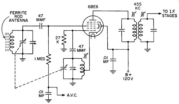
Fig. 6.1. A typical pentagrid converter circuit.
The terms "frequency converter" and "frequency mixer" are used inter changeably by many writers, although a distinction does exist between them. A converter is a tube which produces the oscillator voltage and mixes this voltage with the incoming signal, all within the same tube. A mixer tube, on the other hand, is more limited in scope. It merely mixes or beats together a separately generated oscillator voltage with the incoming signal.
Its function is purely one of mixing. Whichever arrangement is employed depends to a great extent upon the frequencies involved. At the standard broadcast frequencies, a converter tube is more common because it gives satisfactory results and permits an economical arrangement where only an additional coil is needed to generate the oscillations. Fig. 6.1 is an example of a typical frequency converter.
As the signal frequency is raised above 50 mhz, the operation of the oscillator becomes more critical. Instability in output voltage and interaction between the oscillator and the signal are more likely to occur with converters. To minimize these effects, the oscillator is separated from the mixing action, as shown in Fig. 6.2. A separate tube (usually a triode) is employed as the oscillator.
[ 1. This does not exclude the possibility of using a converter for FM receivers in their present band. In fact, some manufacturers do incorporate such circuits using specially designed tubes. However, where good stability and low noise level are desired, separate oscillators are used. ]
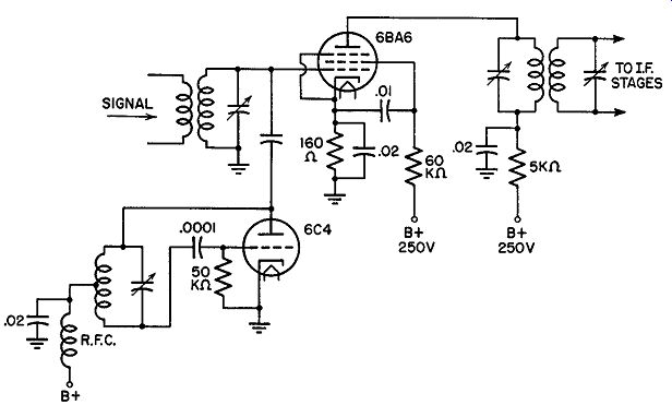
Fig. 6.2. A mixer (6BA6) with a separate oscillator.
The use of a separate oscillator increases the space and cost requirements of the set, but the stability is superior to the frequency converter circuit.
Oscillator Stability. Stability in the oscillator is one of the most important engineering aspects of high frequency receivers. Frequency con version is based upon the fact that a fixed oscillator frequency, beating against an incoming signal, will result in a certain I.F. Little need be said about the constancy of the frequency of the incoming signal. Transmitter channel accuracy is held to within 0.002 percent-safeguarded by many elaborate electronic devices that report instantly any appreciable frequency deviation. At the receiver, the major limiting factor toward stability and the production of a constant I.F. is the stability of the oscillator.
When the oscillator drifts in frequency during receiver operation, the difference, or intermediate, frequency, produced as a result of the oscillator frequency mixing with the signal, changes. A relatively small oscillator drift shifts the signal partially or completely outside the range of the tuned I.F. stages. The receiver output then becomes distorted.
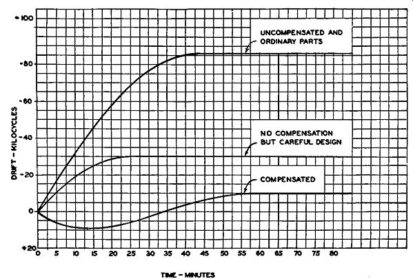
Fig. 6.3. The effect of careful design and compensation on oscillator
frequency drift.
The desired stability in an oscillator has been found to be ±0.01 percent of the carrier or ±10 khz at 100 mhz. With ordinary precautions, such as the use of low-loss sockets, well-placed components permitting free- circulation of air, and air-dielectric trimmer capacitors, the principal drift is due to the capacitance changes within the oscillator tube during the warm-up period.
Of consequence, too, but not quite as important, are the frequency changes due to the variations in oscillator tuning coil and capacitor. The total drift usually amounts to 0.03 percent, or 30 khz at 100 mhz. The drift is never completely developed the instant the set is placed in operation but is attained gradually, perhaps over a period of one-half hour to an hour. After the initial warm-up period, the oscillator frequency levels off to a fixed value unless a sudden change occurs in receiver operation. A typical drift curve is shown in Fig. 6.3. Note that the oscillator always drifts to a lower frequency, a result of the increase in inductance and capacitance due to the increase in temperature.
In an inductance, increase in temperature--due to surrounding heat generated by the tubes, resistors, and transformers in the receiver-expands the copper wire of each turn. Consequently, the length of each winding increases, and with it the effective radius of the coil. Examination of the design formulas governing single layer coils reveals that increasing the length of a coil decreases the inductance by the first power. However, an increase in the winding diameter raises the inductance by the squared power. The net result, then, is an overall increase in inductance. With capacitors, the increase in capacitance is due to the linear expansion of the capacitor plates. The capacitance of a capacitor plate varies directly with its surface area.
Countermeasures. A simple countermeasure against the positive increase in inductance and capacitance is the use of a small, fixed ceramic capacitor having a negative temperature coefficient. Available in many sizes, the proper capacitor can be selected to counterbalance most positive temperature increases to the point where good stability is obtained. It is simple to install and is extensively used by many manufacturers. Other precautionary measures include regulation of the voltage applied to the oscillator plate, adequate electrical shielding of the oscillator plate, and the use of tubes with high mutual conductances and low input and output capacitances. A tube with a high gm provides a strong output. Low input and output capacitances minimize the effect of the oscillator tube on the tuning coil and condensers in the circuit. During the heating-up period, the internal capacitance of a tube changes. This occurs, also, with changes in current through the tube. Hence, to minimize the effect of these changes on the output frequency of the oscillator, it is necessary that the internal capacitances form a negligible part of the total capacitance present across the tuning circuit.
Another method which has been used ( although not recently) by some manufacturers is to operate the oscillator at some low frequency and utilize the second harmonic for mixing. The lower fundamental frequency permits the use of a high lump-circuit capacitance which, in effect, minimizes the stray and tube capacitances.
Harmonic operation is not feasible unless the oscillator voltage can be fed into the mixer tube by way of a separate grid. The capacitative and inductive injection methods shown in Fig. 6.4 (A and B) require a considerable oscillator voltage to be effective. The oscillator, in each instance, must transfer its voltage to the mixer grid tuned circuit. Since this network is resonant to the higher incoming signal (higher by the I.F. value), the impedance presented to the oscillator voltage will be low. Hence, consider- ably more oscillator voltage must be available because of the mismatch. (In any mismatch there is inherently a large waste or loss of power and consequently a greater amount of power must be expended to develop the required smaller value.) Since the second harmonic output is lower than the fundamental, it means pushing this unit more. When the mixing voltage can be applied directly to a separate grid, with only a resistor as the impedance, then a closer match may be made with a resultant rise in efficiency.
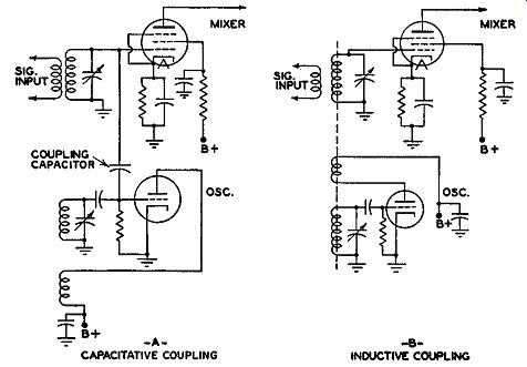
Fig. 6.4. Two methods of coupling energy from between the oscillator
to the mixer.
High-Frequency Converter Operation. When FM broadcasting in the 88-108 mhz band was initiated, certain pentagrid converters which were then popular in AM receivers could not be made to operate satisfactorily at the higher frequencies. The reason for this can perhaps best be under stood by an examination of the action within such tubes. The 6A8 is typical of these converters and will serve to illustrate the points. The conventional schematic and the actual element placement are shown in Fig. 6.5. It is current practice to identify each grid by number, commencing with the grid nearest the cathode. The use of each grid is also indicated.
When the circuit is in operation, electrons leave the cathode area in pulses, controlled by the voltage variations on the oscillator grid, G1. As part of the oscillator, G1 is negative during most of its cycles, becoming sufficiently positive (or less negative) for only a small portion of the time.
It is during these short intervals that the electrons flow past G1 , attracted by the positive potential on G2 and Ga. It is to be noted that G2, the oscillator anode, is not truly a grid, but only two posts or vertical rods without any of the usual grid turns of wire.
Some of the electrons that flow past the screen grid, G3 , come to a halt in the region between Gs and G4 because of the negative potential on the signal grid, G4. This cloud of electrons constitutes a virtual cathode. The number of electrons reaching the plate of the tube is controlled by the variations of the potential on G4 set up by the incoming signal. The overall action then is the control or modulation of the tube's electron flow by two sources, the oscillator grid variations and the input signal changes. The I.F. beat note is produced as a consequence of this interaction.
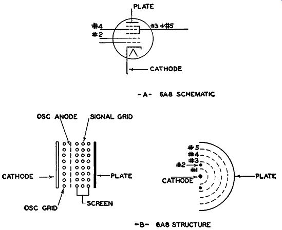
Fig. 6.5. The conventional schematic (A) and actual electrode placement
(B) of a 6A8 converter tube.
It is seen from the above that the number of electrons in the space charge between Gs and G 4 will vary in accordance with the voltage variations on the oscillator grid, G1. Because of the closeness of the space charge to G4, a voltage at the oscillator frequency will be induced into the circuit of the signal grid. The resultant current will not be in phase with the normal oscillator voltage and it will therefore act to buck or cancel out part of the effectiveness of the oscillator voltage. A reduction in gain results, or, in other words, the conversion transconductance is low.
A second and more serious reaction within the tube is the change produced in oscillator frequency by the signal grid. It is the signal grid, G4 ,that determines the number of electrons taken from the virtual cathode as constituted by the space charge and passed on to the plate. This, in turn, has been found to react on the oscillator grid, altering its capacitance with respect to the rest of its circuit and thereby forcing a change in frequency.
With a separate oscillator, this latter effect cannot occur and the stability of the oscillator frequency from a separate source is not affected.
The use of a single tube to function as an oscillator and mixer is at tractive economically and, under the pressure of this advantage, the tube companies have developed pentagrid converters which perform satisfactorily at the FM frequencies. Examples of such tubes are the 6SB7Y, the 6BE6, and the 6BA7.
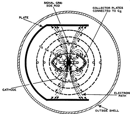
Fig. 6.6. The internal construction of the 6SB7Y tube.
An indication of the altered construction of these tubes can be seen from an examination of the internal structure of the 6SB7Y. (See Fig. 6.6.) At the center of the tube is the cathode, closely surrounded by G1 which serves as the oscillator grid. Beyond G1 is a second grid, G2, which functions as the oscillator plate and also serves to accelerate the electrons emitted by the cathode. Internally G2 is connected to G4, and both elements are properly by-passed so that essentially only a d-c potential is present here. G2 also has connected to it two side plates whose function it is to shield G1 by intercepting any electrons that might be repelled by the negatively charged G3. In this way, interaction between the signal and the oscillator circuits is materially reduced. G3 is located between G2 and G4 and receives the signal voltage. The two supporting rods of G3 are placed in the center of the electron stream traveling from the cathode to the plate. Since the average potential of G3 is negative, the effect of this rod placement is to split the electron stream into two diverging beams, as shown. Because of the particular structure of the elements and the distribution of the electric fields within this structure, electrons repelled back by G3 are forced to strike the side plates of G2, effectively preventing them from reaching G1. G5 is a suppressor grid and is externally connected to ground. Insertion of this suppressor grid raises the internal resistance of the tube and permits a higher conversion gain to be achieved.
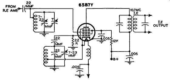
Fig. 6.7. A typical circuit application of the 6SB7Y tube.
Circuit connections for the 6SB7Y are shown in Fig. 6.7. The oscillator coil is connected between the cathode and G1 . G3 receives the signal voltage either from an antenna or an R.F. amplifier. The plate of the tube attaches to the primary of the first I.F. transformer.
In the choice between a frequency converter and a separate oscillator and mixer, there is one additional factor to consider-tube noise. As the number of grids or controlling elements within a tube increases, the amount of tube noise generated likewise increases. In fact, the amount of noise generated in a pentagrid converter, as compared with a straight R.F. amplifier, is in the ratio of approximately 4 to 1. The minimum signal reaching the grid of a pentagrid converter must be this much stronger in order to override tube noise. The noise will also limit the minimum signal that the receiver can amplify successfully without interference from the amplified tube noise.
Before we leave the subject of pentagrid converters, mention should be made of the gain that is obtained when the signal passes through the stage.
Converter gain is defined as where Sc= conversion transconductance, i.e., the effect an R.F. signal voltage has in producing a current in the plate circuit at the I.F. value rp = plate resistance of the tube RL = resistance of tuned plate circuit to the intermediate frequencies In the equation, Sc, the conversion transconductance, is the controlling factor. Sc, in turn, depends upon the oscillator voltage. Increasing the gain of a converter lowers the minimum value of signal voltage needed at its grid to override the noise generated in the tube. Of triodes, pentodes, and penta grid converters, the last possesses the smallest Sc. However, pentodes have a much higher internal plate resistance (rp in the foregoing formula), and the overall gain, using the pentode, is higher.
When a separate oscillator is used, its voltage may be injected at the control grid, cathode, screen or suppressor grids of a pentode tube, or at the control grid or cathode if a triode is used as the mixer. The cathode is convenient, since control over the grid and plate circuits may thereby be effected simultaneously. Control grid injection is more critical than cathode injection because of the increased possibility of interaction between the signal and oscillator circuits. The screen and suppressor grids are seldom used for injection because a greater amount of oscillator driving voltage is needed to obtain a satisfactory degree of mixing.
Oscillator Coupling. Coupling to the control grid may be accomplished either inductively or capacitatively. Both methods are shown in Fig. 6.4.
For cathode coupling, either method of energy transfer can also be employed.
Loose coupling is necessary at the oscillator in order that the tuning circuit shall not be loaded down to any appreciable degree. With loose coupling, the oscillator is least affected by any undesirable feedback and the stability is much better.
Another reason for loose coupling is to keep the amount of oscillator energy that is fed to the mixer at the lowest point consistent with good operation. Every oscillator output contains a large number of harmonics. These harmonics may react with certain undesirable -incoming voltages to produce a difference frequency equal to the I.F. The result is known as a spurious response and, if sufficiently strong, may easily interfere with the desired signal. By keeping the oscillator voltage fed to the mixer as low as possible--consistent with good operation--we decrease the ability of these oscillator harmonics to produce spurious responses. It is well to keep this in mind when either building or repairing a receiver.
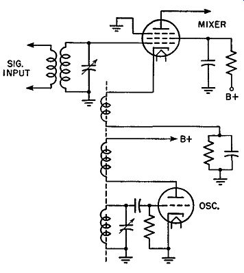
FIG. 6.8. Coupling oscillator voltage to the cathode of the mixer.
Previously the most important reason for not extensively using a triode for a mixer, despite its excellent signal-to-noise ratio and high conversion transconductance, was its relatively large grid-to-plate capacitance. A large C gp permits a high percentage of feedback. Since the signal frequency is higher than the I.F., the I.F. tuning circuit in the plate circuit appears to be wholly capacitative to the signal. All frequencies higher than the resonant frequency of a tuned circuit find it much easier to pass through the capacitor than the coil. When this energy feeds back through Cup, the Q of the input tuned-grid circuit is decreased. In a pentode feedback is negligible because of the extremely small grid-to-plate interelectrode capacitance.
Recently high frequency triodes have been developed in which the coupling between plate and grid is minimized so that undesirable feedback is not too serious. Some receiver manufacturers are using these tubes and the results appear satisfactory.
Types of Oscillators. Three oscillator circuits have been widely used.
These are the conventional Hartley (A), the modified Hartley (B), and the ultraudion oscillator (C), the latter being a modification of the familiar Colpitts oscillator. (See Fig. 6.9.) Each unit, if properly constructed, oscillates readily and possesses good stability. Triode tubes are usually preferred because they require fewer components. Also, there are several high frequency tubes available, such as the 12AT7 and 6U8, which contain two separate sections, one of which is a triode. This enables the designer to use the triode for the oscillator and the remaining section for the mixer.
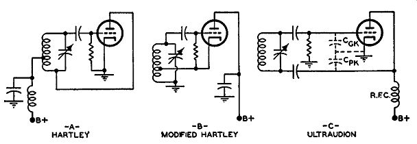
Fig. 6.9. Three popular oscillator circuits.
Crystal Oscillators. Great stress has been given to oscillator stability because of the commanding position that the oscillator holds in the super heterodyne circuit. This feature is especially important in FM mobile receivers (used commercially) where the circuit must be designed to operate under conditions which are considerably less favorable to stability than is ever encountered in home receivers. Furthermore, most commercial operation is restricted to certain specific channels which have been allocated by the Federal Communications Commission for that purpose. Under these circumstances, preset circuits actuated by pressing a push button greatly simplifies receiver tuning and assures the user of a properly tuned receiver each time. Ordinary preset circuits, such as we find in standard-broadcast AM home receivers are unsuitable for commercial usage because of their tendency to drift after a short period of operation. Preset circuits, to have any commercial value, must be able to retain their calibration under the rugged conditions encountered in such operations.
In order to obtain better frequency stability, quartz crystal oscillators are used. Crystals, on a production basis, can be obtained with a stability of ±0.005 percent, which represents 5 khz at 100 mhz. Included in this figure are variations due to temperature and humidity. Desirable stability has been previously stated as ±0.01 percent, which is a lower degree of stability than the 0.005 percent obtainable with a crystal. The need for specially constructed temperature-compensating components in crystal oscillators is also less. This does not mean that the crystal oscillator section need not be carefully constructed, but it does mean that greater leeway is possible in choosing components. Through the use of crystals, push-button tuning be comes perfectly feasible because consistent operation is achieved over long periods of time. For the layman user of an FM receiver, this form of selecting stations assures optimum results without much effort and eliminates entirely the need for any form of tuning indicator.
When crystal oscillators are used, however, reception is restricted only to those stations for which crystals are provided. In other words, each separate frequency to be received requires another crystal in the oscillator in order to develop the proper mixing frequency for the signal. Generally the number seldom runs beyond three or four, although the actual space required is small and a larger number of crystals could be accommodated without increasing the physical dimensions of the receiver appreciably.
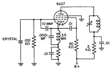
Fig. 6.10. A grid-plate crystal oscillator.
Crystal Oscillator Circuits. In choosing a crystal oscillator circuit, we desire a circuit that will require nothing more than the insertion of the crystal to make it oscillate. For this reason, the tuned-grid, tuned-plate circuit using the crystal would be unsatisfactory. Here, besides the insertion of the crystal, we must tune the plate tank capacitor. A suitable circuit is the grid-plate crystal oscillator shown in Fig. 6.10. The crystal is connected between the grid and ground. In the cathode tuned circuit, the radio frequency choke and the fixed capacitor, 0.0001 mf, tune to a frequency that is lower than the crystal frequency. Good output is obtained on the fundamental and on harmonics. Good output on the harmonics is especially desirable because, as we shall soon see, it is not the fundamental frequency that is used for mixing but a harmonic. In order to accentuate the desired harmonic, the plate tank circuit is tuned to that harmonic. The setting of the plate tank has no effect upon the functioning of the oscillator, but is inserted to insure that sufficient voltage is generated at the harmonic frequency.
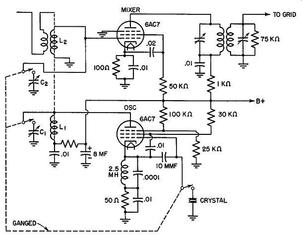
Fig. 6.11. The input stages of a crystal-controlled FM receiver. The
suppressor grid of the oscillator is made slightly positive to produce
a strong output.
For crystal control, the mixing oscillator frequency is generally below the signal input by the I.F. value, say, 10.7 mhz. If the set is tuned to 152 mhz (one of the frequencies allocated to taxicabs), then the m1xmg oscillator must generate a signal which is 10.7 mhz lower than this, or 141.3 mhz. With a strong fundamental crystal frequency near 11.8 mhz, multiplication by a factor of 12 is required to reach 141.3 mhz. (The actual crystal frequency would be 11.775 mhz.) This means that we must use the 12th harmonic of the fundamental crystal frequency. A well-designed crystal oscillator will develop an output which is rich in harmonics and possess sufficient voltage at the 12th harmonic to permit use of the simple oscillator circuit shown in Fig. 6.11. For each frequency a separate crystal and two trimmer capacitors are brought in by a push button or a rotary switch. The trimmer capacitor C1 across L1 is peaked at the factory to resonate L1 to the proper harmonic frequency. L1 and its trimmer do not in any way influence the oscillations of the crystal unit. They merely serve to produce a strong output at the harmonic mixing frequency. The other trimmer capacitor, C2, tunes the antenna input coil, L2 , to the signal frequency. The addition of an R.F. stage would add one more trimmer capacitor.
Instead of operating the crystal oscillator at the 12th harmonic of the crystal, many manufacturers prefer to use a crystal with a low fundamental frequency and then use two quadrupler stages. The advantage of using a low fundamental frequency crystal lies in the fact that it is thicker than a higher frequency crystal. Thicker crystals are more easily manufactured and they can withstand greater current surges without cracking. The thinner a crystal is, the more easily it may break, either from jarring or excessive current flow in its circuit. Outweighing the advantage of a thicker crystal is the fact that a higher order harmonic must be used in order to obtain the proper mixing frequency. The higher the order of the harmonic, the lower the voltage developed in the oscillator. Too low a mixing voltage will not permit full advantage to be taken of the conversion transconductance of the mixer. The output on weak signals may drop so low as to make good reception impossible.
Where to Place Oscillator Frequency. The oscillator frequency, we know, must be separated from the incoming signal frequency by an amount equal to the intermediate frequency. The question then arises as to where this oscillator frequency is to be placed, whether above or below the signal. As far as the outcome is concerned, it makes absolutely no difference which point is chosen, as long as the difference between the point chosen and the signal results in the proper I.F. It is usual in most FM high frequency sets to place the oscillator above the signal frequency. This is similar to the present practice at the standard broadcast frequencies, where the oscillator always operates above the signal. The reasons for the placement of each, however, are quite different. At the lower frequencies, the signal frequency range extends from 550 khz to 1700 khz. The usual I.F. is 455 khz. Suppose we designed the mixing oscillator so that it functioned 455 khz below the signal. Then it would have to cover a range from 95 khz to 1235 khz-or a range where the highest and lowest frequencies were in the ratio of 13 to 1. For a single coil and capacitor to cover a range this wide would present a practical problem that would be most difficult to solve.
Most tuning combinations possess a tuning ratio of 2 or 3 to 1. Here we need 13 to 1. For this reason the oscillator frequency is made higher than the signal. Now let us see what happens. Being above the signal, the oscillator must generate frequencies from 1005 to 2155 khz-or a range with approximately a 2 to 1 ratio. This is easily obtained in practice with one capacitor and coil.
Now let us look at the higher FM band, 88 to 108 mhz. We will assume an I.F. of 10.7 mhz. If the oscillator is placed above the carrier frequencies, its range will be from 98.7 to 118.7 mhz. If placed below the carrier frequencies, its range will be from 77.3 to 97.3 mhz. Design of tuning circuits does not enter into this discussion because both ranges are perfectly possible with one set of components. If we select the lower frequencies, we gain the ad vantages of greater ease in construction, more easily obtained stability, and the use of less critical components. However, with the oscillator generating frequencies from 77.3 to 97.3 mhz, any such signal which finds its way to the antenna will cause interference to nearby television receivers operating on channel 5 (76-82 mhz) or channel 6 (82-88 mhz). On the other hand, when the local oscillator operates above the FM band, no interference results. It is principally for this reason that FM oscillators operate 10.7 mhz above the incoming signal.
EXAM
1. Why are the I.F. amplifiers important in a superheterodyne receiver?
2. What is the difference between the terms "frequency converter" and "frequency mixer"? Which is found most frequently in standard broadcast AM receivers? In FM receivers?
3. Draw the circuit of a mixer with a triode Hartley oscillator.
4. Why is oscillator stability so important in a high-frequency receiver?
5. Discuss the various factors which govern oscillator stability.
6. What are some of the countermeasures employed to stabilize the oscillator frequency?
7. From the standpoint of noise and efficiency, what type of tube is most desirable? Why?
8. Draw representative circuits illustrating how the output of a separate oscillator is coupled capacitatively to the mixer. Illustrate, too, inductive coupling. Is there any other method of coupling possible between the oscillator and mixer? Explain.
9. Why is the frequency drift in an uncompensated oscillator always toward the lower frequencies?
10. In Fig. 6.3, the initial frequency drift of the oscillator frequency is positive.
Explain why this differs from the situation in an uncompensated oscillator.
11. Are frequency converters ever used in FM receivers? Draw the circuit of a frequency converter suitable for high-frequency use.
12. Which three oscillator circuits are commonly employed in FM receivers? Draw one and couple its output capacitatively to a mixer.
13. Is it desirable for an oscillator to produce harmonics? What effect do these harmonics have on 1he receiver operation?
14. What desirable properties should an oscillator tube possess?
15. Why would a crystal oscillator be advantageous in an FM receiver? What disadvantages would it introduce?
16. Are there any limitations on the placement of the oscillator frequency? Explain.
17. Draw the circuit diagram of a crystal-controlled oscillator and the associated mixer.
18. What type of crystal oscillator circuits are used?
19. What considerations govern the choice of a crystal?
20. Explain the operation of a mixer.
21. Define conversion transconductance. Contrast this with mutual conductance of a tube.
22. Why is loose coupling employed between an oscillator and a mixer?
23. Explain why the placement of the oscillator frequency in a standard broad cast receiver is restricted more than it is in a high-frequency FM set.
+++++++++++