To understand the tape recorder it is helpful to examine not only its components but also the audio system of which it is part. The elements of a complete tape recording system are shown in Fig. 101.
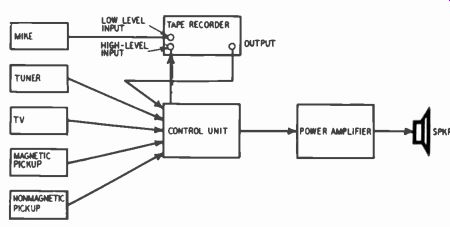
Fig. 101. Basic arrangement of a tape recording system.
Various audio sources are shown feeding into a control unit, a device which has a selector switch for choosing among the input sources, plus bass and treble controls, pre-emphasis and equalization for magnetic phono pickups, a gain control and sometimes a loudness control, high-cutoff filter, low-cutoff filter, etc. The audio signal goes from the control unit to a power amplifier and then to a speaker system. Almost all present-day control units also have an output for simultaneously feeding the audio signal to a tape recorder. The power amplifier may consist of two units in either a stereo or a split-channel system where the highs go through one amplifier and the lows through another. Similarly, the speaker system may consist of one or several speakers fed through a cross over network which apportions the frequency spectrum to the appropriate units. The complete system may use stereo speakers or several speakers spaced apart to obtain a distributed-source effect.
Tape recorders are almost always designed to record both from a low-level (a few millivolts of signal) and from a high-level source (about 0.1 to several volts of signal). In Fig. 101 high-level input sources are shown connected to the control unit. The tuner, TV and nonmagnetic phono could be fed directly into the recorder, but at the inconvenience of having to go through the process of changing connections when the source is changed, be cause tape recorders customarily do not have the ample selection facilities that control units do. As a rule, recorders do not provide the equalization required by magnetic phonograph cartridges to obtain flat frequency response and, therefore, they cannot satisfactorily accommodate the signal directly from a magnetic cartridge. However, one occasionally finds a recorder that is an exception to this rule.
In playback, the tape recorder feeds into the control unit just as do the other high-level audio sources. Or, if one chooses, the recorder output can go directly to an audio amplifier, but at the cost of having to make and unmake connections. (One can see that it is possible-sometimes, not always-for a feedback path to be set up, whereby the recorder output goes into the control unit, from there into the recorder input and again from the recorder output.) Thus, the tape recorder plays a dual role in relation to the complete audio system. First, incoming signals are fed to it for recording purposes. Second, in playback it has the same role as other audio sources.
The term tape recorder tends to be somewhat obscure when it comes to defining what elements of a complete recording system it contains. Most moderate-price "home" recorders include several elements outside the block labeled "tape recorder." They generally include a power amplifier (infrequently meeting high-fidelity standards), an inexpensive speaker or speaker system and a medium-grade microphone. Some have a tone control, thereby duplicating the function of a control unit, and in a few cases the unit has included an AM radio tuner. Thus one may well ask, Where does the tape recorder begin and end? Fig. 102 shows what may reasonably be called the basic elements of a tape recorder. These may be sorted into transport and electronics, the latter consisting of the tape amplifier, the heads and the tape. This division is not a clean-cut one because the heads and tape are physically located on the transport. The amplifier consists of two basic elements-the record and playback sections. The latter does not necessarily include a power amplifier and speaker.
The path of the audio signal is fairly obvious. The incoming signals (high and low level) go into the record section (singly or together, depending upon the amplifier), then to the record head and onto the tape. In playback, the signal from the tape enters the playback head, goes from there into the playback section and is finally delivered to the output.
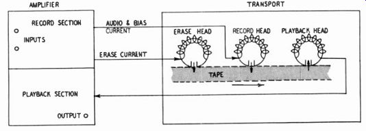
Fig. 102. Fundamental units of a tape recorder.
Fig. 102 shows separate record and playback heads as well as separate record and playback sections. This is for diagrammatic convenience, although moderate-price home recorders (in the majority) use the same head for record and playback. They also employ essentially the same amplifier stages for both functions, the necessary changes being made through a switching system.
Variations in use of tape recorder elements
There are many variations of the basic arrangement of audio components for the purpose of recording and reproduction. One has already been mentioned--in some recorders the same head and same amplifier stages are used for both record and playback.
Playback only
Some tape machines are purely playback devices and may be viewed in the same role as any other audio source. This is particularly true in the field of stereo, where the home user has little opportunity, equipment or know-how for making stereo recordings. There are similar machines for playing only conventional single-channel tape. In either case, the growing availability of pre recorded tape, both single-channel and stereo, is increasing the demand for the so-called tape player, that is, the strictly playback machine which is comparable in its role to the disc phonograph.
Where it is desired only to play tapes and not record them, it is sometimes possible to dispense altogether with the tape amplifier. A few control units have a special input for accepting a signal directly from the playback head. The necessary equalization and amplification are provided by the control unit, much in the same manner as for a magnetic phono cartridge.
Mixing
A considerable number of variations are possible in the mixing of input sources. Thus one might employ a multiple-microphone setup, a combination of microphone and phonograph, a combination of microphone and electronic instrument, etc.
Sound-on-sound
"Sound-on-sound" recording where it is desired to record twice or more on a tape without erasing the previous recording, may ...
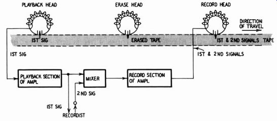
Fig. 103. Elements in sound-on-sound recording.
... be likened to a double exposure in photography. A common illustration is a recording of the same individual playing two or more instruments at once. To do this it is necessary to locate the playback head so that it precedes the erase head, which is then followed by the record head in the normal manner; or else an extra playback head (if the transport has room) is situated prior to the erase head. The sequence is shown in Fig. 103. After the first recording is made in the usual manner, the tape is re wound. The first signal is then played by the extra or relocated playback head and fed into a mixer; the performer listens to the first signal through earphones and produces the accompanying second signal, which is also fed into the mixer. The two signals go into the record amplifier, then to the record head and onto the tape, which has been freshly erased by the erase head. The sound-on-sound process can be repeated to add a third signal, a fourth and so on.
Echo effect
Artificial reverberation or "echo effect" increases many listeners' pleasure by adding a feeling of spaciousness and warmth.
Everyone who has ever sung in a bathroom is aware of the glamorizing effect of reverberation.
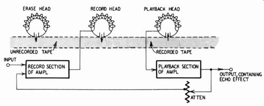
Fig. 104. Method for production of an echo effect.
Fig. 104 shows how an effect of this sort may be obtained with the aid of a tape recorder. After the signal is impressed on the tape by the record head, the playback head picks up this signal and adds some of it back to the record head, via the playback and record amplifiers. The amount of signal fed back is considerably attenuated, as in true reverberation. The degree of echo effect is partly determined by the distance between the record and playback heads; normal spacing, at 15 ips, causes the echo to appear about 1/10 second later. In specially designed tape machines, this time interval can be varied. Also, the quality of the echo effect can be improved in such machines inasmuch as they are equipped with several playback heads spaced along the tape, each of which feeds the signals in successively attenuated form back to the record head.
Tape duplication
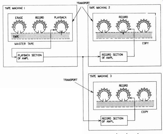
Fig. 105. Duplication of tapes. If machines used are specifically for
duplication, machine I has only a play back head and playback amplifier,
while machines 2, 3, etc. have only a record head and record amplifier.
In the production of phonograph records a stamper impresses the entire arrangement of sound patterns all at once on the vinylite. In making tape duplicates, however, the master copy has to be played from beginning to end and one or more duplicates are made as the master is played, usually at a speed higher than normal to reduce the time. Fig. 105 shows the basic idea, of which there are some variations. The master tape is played on tape machine 1 and the signal, after leaving the playback section of the amplifier, goes to the record section of one or more tape machines. Where duplication on a mass basis is required, special machines are used, one being a master playback unit only (no record function) and the others designed for record only. In practice, up to about 10 or 12 record machines may be used with one master playback unit.
Amplifier elements
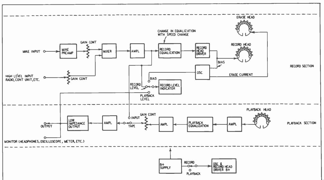
Fig. 106. Block diagram of a tape amplifier for use with separate record
and playback heads.
Fig. 106 shows the basic elements of an amplifier intended for use in a tape recorder having separate record and playback heads as well as an erase unit. This diagram represents a high-quality amplifier containing the functions generally considered desirable.
The exact sequence of functions is not the same in all amplifiers of comparable quality but the dissimilarities among them are generally minor.
Because the signal from a microphone is only in the order of millivolts, an extra amplifier stage is required when recording from this source. Some machines contain facilities for mixing low- and high-level inputs. Others require an external mixer. The relative levels of the low- and high-level incoming audio signals are adjusted by the respective gain controls for each source before they are combined in the mixer. In most home recording, either the microphone input or the high-level input is used alone so that the gain control of the one not in use is turned all the way down.
Following the mixer comes further amplification and then equalization to provide the recorded frequency characteristic. This, in conjunction with the playback frequency characteristic, will result in a more or less flat response over the audio range in playback.
Especially in higher-price machines, the recorded frequency characteristic conforms to the NARTB (National Association of Radio & Television Broadcasters) standard.
The equalization used in recording depends upon the tape speed. If the recorder operates at two (or more) speeds, provision is usually made for modifying the equalization when the speed is changed.
After equalization and before the signal goes to the record head, a third stage of amplification is required. This may be termed the record-head driver. Along with the audio signal, there is also delivered to the head a high-frequency current called bias, ordinarily ranging between 30,000 and 100,000 hz. The bias current reduces distortion to an acceptable level and increases the amount of signal recorded on the tape. Bias may be likened to a catalytic agent in a chemical reaction, promoting the desired process.
The oscillator shown in Fig. 106 has a dual function. In addition to providing bias for the record head, it provides a fairly substantial amount of current to enable the erase head to perform its function efficiently. Although a few recorders in the past have used separate bias and erase oscillators, it is now almost standard recorder practice to employ a common oscillator for both of these functions.
In playback, the signal from the head is of very low level and goes through a stage of amplification before being equalized to produce the desired flat frequency response over all or most of the audio range. Next comes a second stage of amplification, followed by a gain control, further amplification and a low-impedance output stage. The latter permits a substantial run of cable between the tape recorder and the next audio component (usually the control unit) without undue loss of high-frequency response due to the capacitance of the cable. Moderate-price recorders, however, generally have a high-impedance output so that only a few feet of cable can be used safely.
The principal purpose of the record-level indicator is to show the user whether he is recording at a satisfactory level. Too high a level produces tape distortion. At a very low level the noise present in all audio systems will be unduly large compared to the desired signal. The record-level indicator in a high-quality amplifier is customarily employed for two additional functions One is to measure the bias current supplied to the record head. Insufficient bias increases tape distortion although it may improve high-frequency response. Too much bias attenuates treble response and possibly also increases distortion. The other function is to measure the signal level on a tape that is being played. back.
It may be desirable to compare levels on various recorded tapes or to set correctly the level of a signal being fed to a following audio component.
Fig. 106 shows that the last two stages in the playback section can be switched to either the earlier playback stages or the record stage. Thus, when a recording is being made, the user can switch between the incoming and the recorded signals to determine whether the recorded audio signal is an adequate facsimile of the incoming one.
Finally, Fig. 106 shows that the record and playback sections are fed by a common power supply. To use the tape recorder for playback, B plus to the oscillator and to the record-head driver is removed. This prevents accidental erasure and possible recording of noise.
Amplifier for a two-head machine
Professional and semiprofessional tape recorders are customarily three-head machines. That is, they employ separate record and playback heads (plus an erase head) which permit simultaneous recording and playback. This enables the user to determine whether a recording is proceeding satisfactorily and facilitates adjustment and alignment of the machine. However, the majority of home units, for reasons of economy, have only two heads, one of which serves for both record and playback. The other, of course, is the erase head. Thus the cost of a head and of several amplifier stages is saved, with a certain amount of relatively in expensive switching substituted to permit most of the amplifier to serve in a dual capacity for record and playback.
Fig. 107 shows the basic elements of the tape amplifier in a typical moderate-price recorder with a single record-playback head. Although most such recorders also include a power amplifier and a speaker system, these are not considered part of the amplifier proper and are therefore omitted from the diagram and discussion.
Moderate-price recorders seldom provide mixing facilities with separate gain controls for the low- and high-level inputs. Instead, there is usually a common gain control. However, inasmuch as many audio sources, such as tuners, TV sets, etc. have their own gain controls, adjustment of the low- and high-level sources to the desired relative levels (when both are used at once) can often he accomplished by means external to the tape amplifier. Although in some home recorders it is possible to mix both sources more often this cannot be done because inserting the high-level cable into the preamplifier opens the low-level connection to the gain control (thereby eliminating hum and noise from the extra amplification stage for low-level sources). Mixing must then be accomplished by external means. A few audio control units afford mixing facilities; the majority do not. However, separate mixers can be purchased.
Following the gain control comes an amplification stage, record equalization and the record-head driver. In some amplifiers different equalization is used in record than in playback. On the other hand, a very substantial number (perhaps the majority) of home recorders employ the same equalization in record and playback, as shown by the dash-line connections.
Without any equalization whatever, the frequency response of a tape recorder exhibits a substantial drop at both the bass and high ends. Therefore, both bass and treble boost are required.
For best results, treble boost should take place essentially in re cording and bass boost mostly in playback. However, partly as an economy measure and partly to overcome hum problems, many home recorders accomplish half the treble and bass boost in re cording and the other half in playback, thus permitting use of the same equalization in both modes of operation.
Fig. 107 shows that, as in Fig. 106, the oscillator feeds the erase head and supplies bias to the record head in the record mode. In playback, B plus is removed from the oscillator to prevent erasing the tape. Also, the record-level indicator functions only in the record mode.
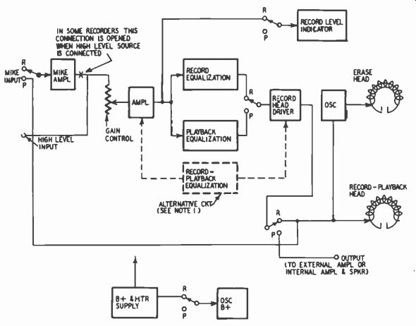
Fig. 107. Basic elements of a tape amplifier for use with a record-playback
head.
Many two-head recorders use the same equalization in record and playback.
In the diagram shown above, all switches operate simultaneously. (R means record, P is playback.)
The simultaneous switching functions in an amplifier designed for a two-head recorder can be fairly extensive and are at least three in number: (1) supplying the first amplifier stage with either the microphone signal or with the signal from the head; (2) feeding the signal from the last amplifier stage (labeled record-head driver) either to the head or to the output; (3) shutting off oscillator B plus in the playback mode. In addition, the record-level indicator is often disconnected in the playback mode, and different equalization may be introduced when changing from record to playback. Also, though not shown in Fig. 107, different equalization may be provided for operating at different tape speeds. Thus there may be as many as six simultaneous switching functions in all.
Other tape recorder elements
Let us take a brief look at the other basic elements of a tape recorder in terms of the functions they serve: the transport, the heads and the tape. Inasmuch as this guide is essentially concerned with the electronics of a tape recorder, relatively little will be said about the transport. However, greater attention is given to the tape and to the heads in view of the important bearing they have upon design and operation.
Heads
The tape recorder employs three types of heads: erase, record and playback. In most home recorders the record and the playback functions are served by the same head which is switched from one function to the other as required. Some recorders employ heads that also incorporate the erase function. However, these actually consist of two electrically separate heads contained in the same housing. A typical record-playback-erase head is shown in Fig. 108.
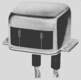
Fig. 108. Combination record-playback and erase head (half track.) Courtesy,
Shure Brothers, Inc.
A head that has quite recently become of importance is the "in-line" unit used for recording and playback of stereophonic sound. This consists of two sections, each equivalent to a separate head, mounted directly above one another so that their gaps are in a vertical line (Fig. 109). One section records or plays the upper part (track) of the tape while the other simultaneously operates on the lower part. Each section must be small enough so that the two together occupy about the same space as a conventional head. For stereo purposes, two conventional heads can also be used as shown in Fig.109. These heads are spaced 1.25 inches apart, one operating on the lower half of the tape and the other operating on its upper half. The conventional arrangement is that for a tape viewed from the backing (coating toward the heads) and traveling from right to left, the lower portion bears track 1, for the left speaker, while the upper portion bears track 2, for the right speaker. For single-channel material, the heads are situated opposite track 1.
Single-channel recording may be either full-track or half-track, that is, the head may be designed so that its active portion (the gap) spans either the full width of the tape or about half. For professional purposes, full-track recording is customarily employed because of greater signal output and because editing of the tape is practicable only when one track is recorded. Most home recorders, however, employ half-track heads. Assuming that the tape moves from right to left, the lower half of the tape is recorded. The reels may then be reversed and the other half of the tape recorded, thus doubling the amount of playing time obtained from a reel of tape.
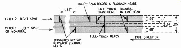
Fig. 109. Tape tracks, dimensions and head (gap) locations, viewed with
the tape backing toward the reader and the coating toward the heads.
A full-track head is exactly that, its gap covering the entire width of the tape. The gap of a half-track head, however, usually covers about 0.09 inch. Two tracks add to about 0.18 inch, leaving 0.07 inch in the middle of the tape as a safety island to prevent the overlapping of tracks and consequent cross-talk between the recordings on the upper and lower tracks. The erase-head gap spans about 0.11 inch to insure full coverage of the recorded track, with something to spare. These various dimensions are shown in Fig. 109.
Assuming the tape travels from right to left, in practice the lower edge of a half-track head is usually not exactly flush with the bottom of the tape. Instead, it is located 10 or 20 mils (thousandths of an inch) above the bottom, thus consuming some of the safety margin of 70 mils. If 15 mils, for example, are thus used for each track, the safety island is reduced to 40 mils.
The full-track record and playback heads, because of the greater tape width they cover, result in an 8- or 9-db-higher signal output, everything else being equal. As a result, a higher signal-to-noise ratio may be obtained with full-track heads although, due to the fact that they also pick up more hum and tape hiss, the difference is often only 3 db or so.
The tape
Virtually all tape made today for audio recording purposes utilizes a plastic base coated with a magnetic substance. The coating is a mixture of ferrous oxide and synthetic resins which enable the oxide to adhere firmly to the base.
The magnetic tape ordinarily used is about 0.25 inch wide and available in three thicknesses. The thinner tapes permit increased playing time for a given reel size because greater lengths can he wound on the reel. Standard tape is about 0.0021 inch. Long-playing tape, introduced a few years ago, is two-thirds as thick and therefore offers an increase of 50% of playing time.
Of more recent date is the extra-long-playing tape, which is half the thickness of standard tape and therefore doubles the playing time of a reel. Unfortunately, it is too fragile for general home use.
The reel size most common in home use has a diameter of 7 inches. It accommodates 1,200 feet of standard tape, 1,800 feet of long-playing tape or 2,400 feet of extra-long-playing tape. At 7.5 ips (inches per second), the speed most commonly employed by home recorders for high fidelity, 1,200 feet translates into 32 minutes of playing time. The thinner tapes offer 48 or 64 minutes per track on a 7-inch reel. If the tape is recorded half-track, as is usual, a two-track recording can last 64, 96 or 128 minutes; that is, from about one to two hours.
Most professional machines can take a reel up to 10.5 inches in diameter, which holds twice as much tape as a 7-inch reel.
This doubles the playing time, resulting in a maximum of about 4 1/4 hours. However, professional machines usually operate at 7.5 and 15 ips, so that with a 10.5-inch reel they can provide the same playing time as a machine accommodating only 7-inch reels and operating at 3.75 and 7.5 ips. Reels greater than 10.5 inches can be accommodated by a few professional machines while reels smaller than 7 inches can be played by virtually any unit.
Another distinction that can be made is that between regular and high-output tape. Output refers to the amount of signal obtained from the tape playback at a given level of distortion. Part of the increase in high-output tape usually results from the ability of the tape to accept a stronger magnetic field in recording with out an increase in distortion. And part results from the greater sensitivity of the tape, that is, a greater recorded flux for a given magnetic field generated by the record head. There are also variations in output between brands and between batches within the same brand. These variations, however, are usually minor compared with the difference between regular and high-output tape, which is 8 db or more.
Tape must meet several. mechanical requirements-strength, smoothness and limpness. Not only is the tape subject to considerable tension because the supply and takeup reels tend to rotate in opposite directions, but sudden starts and stops and rapid wind and rewind subject the :ape to additional stress. A breaking strength of several pounds is therefore required. Also, the tape must be able to withstand considerable strain before becoming permanently stretched.
Tape must maintain very close contact with the heads for good results; therefore, smoothness of the coating is vital. Not only does a rough coating prevent continuous close Contact, but it also causes undue head wear and noise due to vibration against the heads. Inasmuch as many recorders use pressure pads to hold the tape firmly against the heads, it is also important that the back of the tape (the base) be smooth. Tapes contain small amounts of various lubricants to promote smooth operation.
To enable it to hug the heads closely, the tape must be limp.
This quality further permits the tape to make sharp turns around guides and tension devices with ease.
The transport
The fundamental purpose of the transport mechanism is to move the tape past the heads at a rate which is both uniform and accurate. Erratic motion manifests itself in wow, flutter and noise, which are deviations in the frequency of a tone. A transport of professional quality keeps the average value of these deviations below 0.2% of a test frequency (usually 3,000 hz) recorded on the tape. (See Fig. 110 for photos of tape transport mechanisms.) Wow is evident as slow variations in pitch (a few times a second) which cause prolonged notes, such as those of a piano, to go pain fully sour. Flutter refers to pitch variations substantially higher in frequency that produce a warbling effect. Extremely rapid speed variations result in noise. The last phenomenon may not be due to the transport but to tape that is not smooth or to improperly adjusted pressure pads. This causes high frequencies to have a coarse, grainy quality and is sometimes referred to as frequency-modulation noise. The principal sources of frequency-modulation noise are the varying frictional forces acting upon the tape as it passes over the recording heads and guides. This action is similar to that of drawing a bow across a violin string.' Inaccurate motion manifests itself as a steady deviation from correct pitch, which may or may not be bothersome, depending upon the musical training of the listener's ear. High-quality transports maintain an accuracy of speed better than 0.2%, which means that a recording supposed to last exactly 32 minutes will deviate no more than 3.8 seconds in either direction.
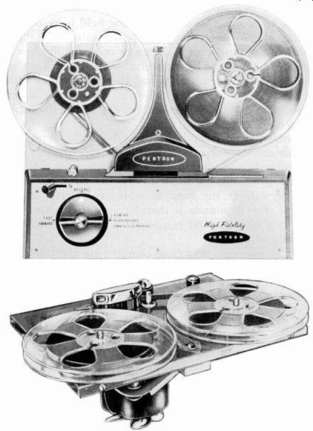
Fig.110. Tape transport mech. (tape decks).
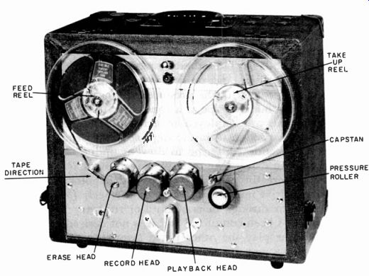
Fig. 111. Tape recorder showing the principal exterior components of
the transport mechanism. Courtesy. Presto Recording Corp.--- FEED REEL
TAPE DIRECTION ERASE HEAD RECORD HEAD PLAYBACK HEAD TAKE UP REEL CAPSTAN
PRESSURE ROLLER
Fig. 111 shows the basic elements of a transport mechanism.
The reel of tape to be recorded or played is mounted on the left hand spindle while a takeup reel is mounted on the right one, although in many recorders the opposite arrangement is used. In sequence, the tape moves past the erase, record and playback heads.
If the machine is being used for playback, the erase and record heads are inactivated. In the majority of home recorders, the record and playback functions are performed by the same head which is switched from one function to the other.
The tape is moved at the required speed as the result of being pinched between a motor-driven capstan and a spring-actuated rubber roller, called the pressure roller. When it is desired to play or record, a lever causes the pressure roller to spring against the capstan, and the roller together with the capstan drives the tape. Guides keep the tape in line with the heads and prevent its weaving up and down. The means for keeping the tape in firm contact with the heads is not shown.
The feed and takeup reels tend to rotate in opposite directions, though not with such force as to rupture or stretch the tape. In motion, the tape moves not only against the torque of the supply reel but also with the torque of the takeup reel which tends to rotate at a speed considerably greater than that required to wind the tape. Obviously, the tape would break were it not for a device that permits the reels to slip in one fashion or another. Slippage is provided by using clutches or belts or, where the reels are directly motor-driven, by operating these motors substantially be low their rated voltage. Thus there is more or less a balance of forces at each end of the tape, pulling in opposite directions. The capstan in conjunction with the pressure roller acts as a metering device which pays out the tape at a constant rate.
Various methods are employed to drive the capstan, seeking sufficiently positive action to insure high accuracy of motion, yet with enough mechanical filtering to prevent undue wow, flutter and noise. Capstan drives take three principal forms: (1) a direct-motor drive, where the capstan is part of the motor shaft; (2) a linkage to the drive motor through an idler wheel; (3) a linkage to the drive motor through belts of cloth or rubber.
After a reel has been completed and it is not desired to reverse reels to record or play the other track (assuming half-track re cording), the tape may be rewound. The pressure roller is disengaged from the capstan and, through mechanical or electrical means, greater driving torque is applied to the feed reel than the takeup reel. On the other Land, to wind in the opposite direction, greater torque would be applied to the takeup reel.
Although very good results have been obtained by using one motor to perform the three functions of driving the capstan, feed reel and takeup reel, top-quality transports employ three motors, one for each of these functions. The highest-price machines em ploy a hysteresis-synchronous motor to drive the capstan. This permits the greatest timing accuracy since the speed is exactly determined by the frequency of the ac power line, customarily 60 hz.
Not shown in Fig. 112 is the means employed to maintain firm contact between the tape and the heads. Such contact is vital to maintain high signal output, particularly at high frequencies.
Two methods are in use. Virtually all moderate-price recorders employ a pressure pad, that is, a piece of felt mounted on a metal arm, which is held by spring pressure against the back of the tape as it moves past the heads. The other method, commonly used on professional-grade recorders, is to employ guides and rollers so located as to cause the tape to follow a course assuring firm contact with the heads.
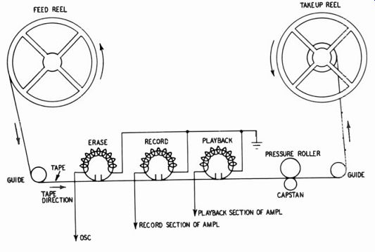
Fig. 112. Drawing of the principal parts of the transport mechanism.
The subject of transports merits voluminous discussion, and all that can be done here is merely to list various other elements of transports, some of which are found only in the better mechanisms: brakes for bringing the reels to a rapid halt; means for changing the speed at which the tape is driven; a mechanical inter lock which prevents rapidly rewinding or winding the tape when the mechanism is set for record or play; a tape lift which spaces the tape slightly away from the heads during rewind or forward wind to reduce head wear caused by the abrasive action of the tape; a mechanical arrangement which permits ready access to the portion of the tape opposite the record and play heads to facilitate marking the tape for editing purposes; automatic shutoff of the transport if the tape breaks or runs out; space for mounting additional heads to permit special uses such as sound-on-sound and echo-effect recording; automatic withdrawal of the idler wheel (if this method of capstan drive is employed) from the motor shaft and capstan when the transport is shut off, to prevent the idler from developing flats; a tape position indicator so that the user can readily locate any portion of a tape recording; Mu-metal covers for the heads to shield them from hum pickup, particularly by the playback head.