THE recording amplifier is important in determining record quality. It may be a completely conventional amplifier, but its quality must be far better than the usual public address or general purpose unit.
There must be no hum, restricted frequency range, peaks and valleys in the response curve, harmonic distortion, or inadequate power-handling ability. A good record may be played on a mediocre amplifier, and an untrained listener may not be able to detect much lack of fidelity ; but good quality can never be realized in a record made with an imperfect amplifier.
Briefly, here are the requirements for a good recording amplifier:
1. Flat ( 2.5 db) frequency response from 50 to at least 8,000 cycles is necessary. This may be subject to modification with equalizers but the amplifier should have a flat response curve to begin with.
2. Noise-hum and tube hiss-must be at least 40 db below normal program level. When the sound input is very low, the gain control must be advanced so that a usable groove is cut. Even under these conditions, hum and tube noise should be inaudible. Professional standards require hum level of 45 to 50 db below program level.
3. A full rated output of 10 times the normal power required for the cutter will take care of instantaneous peaks on crescendos. These will cause great distortion if the amplifier does not have sufficient power. For amateur work, 10 watts is a suitable compromise between expense and quality and for professional purposes, 30 to 50 watts is not too high. If speakers are to be connected with the cutter, the power rating must be increased proportionately.
4. Total harmonic distortion at full recording level should never exceed 5% for amateur use; and for ideal quality, it should be much less. In professional equipment, maximum distortion is 3% at 10 db above normal recording level. Excessive distortion, plus that in the playback amplifier, will be very noticeable. While it is possible to iron out certain nonlinearities in frequency response by equalization in the playback system, harmonic distortion, once it is on the record, is there to stay!
5. The output stage should consist of triodes or feedback-stabilized beam or pentode tubes. A cutter varies its impedance with frequency. Unless the power stage of the amplifier has comparatively low effective plate resistance, the varying load impedance of the cutter will affect it.
6. Even though a high-output microphone is to be used, an amplifier gain of 110 db is not excessive. Lower-level devices may be used later.
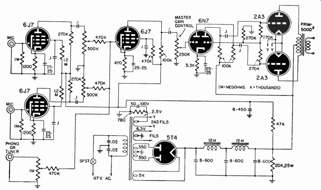
Fig. 901-Schematic diagram of a recording amplifier.
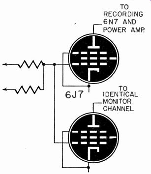
Fig. 902-Coupling monitoring stage for recording amplifier.
7. The system should have adequate gain controls and switching circuits, all of which must be noiseless. A volume indicator is necessary.
Figure 901 is a schematic diagram of a recording amplifier suitable for amateur use. If the power output stage is changed to allow higher rated power output, it will also be suitable for professional use. The 2A3's shown are rated at 10 watts.
The input circuits allow for 2 low-level microphones and 1 high level phonograph pickup or radio tuner. The microphone volume controls are placed after the preamplifier tubes in order to minimize the noise which may develop after a period of use. All 3 input gain controls are connected, through individual 0.47-megohm isolating resistors, to the grid of the 6J7. All discernible interaction between these controls is eliminated by the isolation resistor.
The use of a phase inverter of the self-balancing type, instead of an interstage transformer, eliminates the possibility of inductive hum pickup, has an inherently flat response curve, and saves the price of a high-quality transformer. The use of a master gain control (a potentiometer on grid No. 1 of the phase inverter) is very valuable in recording work when more than one microphone is in use. Fade-outs and fade-ins are possible. With the input controls in such a position as to give the best range of control, the master control may be set to give the proper recording level.
The power stage is a pair of push-pull 2A3's in class AB1, rated at 10 watts output. The naturally low plate resistance of triodes minimizes the effects of the changing cutter impedance. For higher power, any other output stage with the required power and harmonic distortion may be substituted. In normal use, beam tubes, such as 6L6's, have a higher power gain and increased over-all gain. But if beam tubes are used, feedback must be incorporated, and the power gain is about the same as that obtained with 2A3's. Total possible output will be greater, however, with beam tubes than with triodes.
It is essential that the highest-quality output transformer be used.
All parts must be of the best quality-junk-box components are out of the question.
If more input channels are needed, they may be inserted without difficulty. Additional 6J7's may be used, with their output gain controls, similar to the ones shown and isolated by 0.47-megohm series resistors. If additional high-level inputs are needed, the phono input shown may be duplicated. There is a limit, of course, since the larger the number of inputs, using this system, the greater the possibility of interaction, between them. Normally, 4 is the maximum.
In all professional recording systems, there must be facilities for monitoring while the recording is in progress. It is not a good idea to connect a loudspeaker to the same power stage which is feeding a cutter, because a voice coil also changes in impedance with frequency.
Fig. 902 shows a very practical method of getting around this. A second 6J7 is connected to the grid of the second stage 6J7 in Fig. 901.
It connects to an identical phase inverter and output stage. There can be no interaction between cutting and monitoring circuits, and the level of the monitor speaker can be controlled by its own potentiometer with out affecting the recording. Since the power supply current requirements will be much greater, it is often advisable to use a separate power supply for the monitor channel. It may be necessary to insert some equalization in the recording amplifier to correct cutter deficiencies.
In this case, a loudspeaker connected to the cutting amplifier would not show a true picture of the sound, and the separate monitor channel is a necessity, even if only for playing back the finished records.
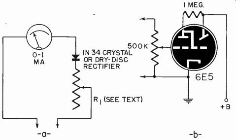
Fig. 903-Two types of volume indicator: (a) suitable for magnetic cutter;
(b) crystal cutter hook-up.
Fig. 903 shows 2 different types of volume indicator. If a magnetic cutter is connected to the secondary of the amplifier's output trans former, the circuit of Fig. 903-a is probably the best. The value of resistor R1 should be at least 10 times the output impedance of the transformer. The exact value will have to be found by experiment.
If a crystal cutter is used (connection methods are detailed in Section 11), a meter usually cannot be used across the amplifier output. In that case, the circuit of Fig. 903-b is probably the best. Although actual experiment is needed, the grid potentiometer of the 6E5 magic-eye tube probably can be connected to the first grid of the phase inverter in the amplifier of Fig. 902. If that is done, choose both controls so that the total parallel resistance across the 6N7 grid, when the recording master gain control is wide open, is of the proper value. The value of the eye tube grid control is not critical.
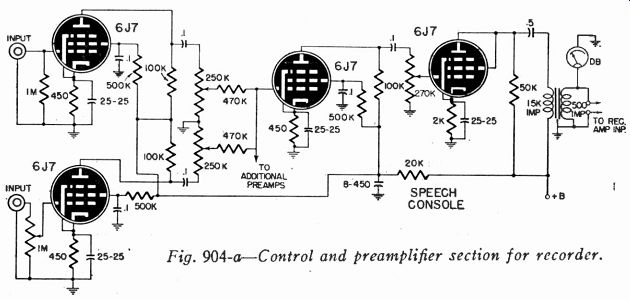
Fig. 904-a-Control and preamplifier section for recorder.
When the circuit in Fig. 903-a the amplifier and the cutter at the manufacturer and measured with a variable resistor or potentiometer in the needle points to about 1/3 scale.
is used, a constant tone is fed into proper level (given by the cutter voltmeter across the cutter). The series with the meter is varied until This point should be marked on the meter scale. The meter then shows recording level, enabling the recordist to reduce gain if the sound is too loud.
When the circuit in Fig. 903-b is used, the tone should be fed in, and the 6E5 grid potentiometer adjusted until the eye just closes. The closing of the eye indicates maximum level, and gain can be adjusted accordingly during cutting.
Most professional studios and all broadcast stations use a system which is somewhat more flexible, though less compact. A typical setup of this type is shown schematically in Fig. 904. The first unit is the control and preamplifier section. Two high-gain inputs are shown, connected in the same manner as in the amplifier previously discussed.
The tubes used are pentodes, 6J7's. As before, tubes may be eliminated and high-level devices connected directly to volume controls, if the inputs need not have preamplifiers. Fig. 904-a shows the first unit.
The output stage is a triode-connected 6J7, feeding into a tube-to-line transformer, whose secondary impedance is 500 ohms. The output level is generally zero db (6 milliwatts) or zero VU (1 milliwatt in 600 ohms) if the newer type of volume indicator is used.
A master gain control is provided at the grid of this 6J7. The control and preamplifier unit-usually called the speech console-is complete in itself, with its own power supply (housed in a separate case to eliminate hum pickup) and mounted in a sloping-panel steel cabinet.
The recording amplifier (Fig. 904-b) is a separate unit; it is similar to the amplifier of Fig. 901, but it lacks the input stages. Although a 500-ohm-to-grid input transformer may be used, none is needed. A 6C5 has been used as the input stage, with a 500-ohm resistor connected across its grid. The 6C5 makes up the gain which a step-up trans former would have given, but it is not frequency-discriminating though cheaper than a good transformer. The 500-ohm grid resistor provides the proper impedance for terminating the line from the console.
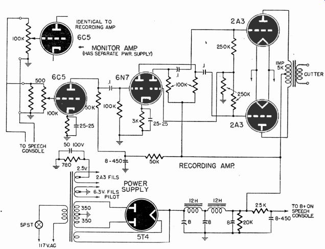
Fig. 904-b--Recording amplifier section; to be fed from preamplifier.
A system like this is flexible for several reasons. A professional recording firm may have several studios. If each studio has a console, simple switching will connect the proper console to the proper recording amplifier. If equalization is necessary, an equalizer may be inserted in the line between console and recording amplifier or in the recording amplifier. Since the 500-ohm line may be much longer than a high-impedance line, the performers and control point may be at almost any distance from the recording machine. A standard decibel or VU meter may be connected directly across the line as it is in the diagram, and it will show actual db or VU, rather than the arbitrary units which must be used in the two other volume indicators previously described.
In addition to console and recording amplifier, a monitor amplifier is shown in Fig. 904-b. This monitor amplifier is similar to the recording amplifier, except that there is no 500-ohm grid resistor in the first stage. The high-impedance grid circuit placed directly across the line is known as a bridging input.
This entire system makes use of unbalanced lines, that is, one side of each line is grounded. In most broadcast stations, balanced lines in which a center tap of each transformer is grounded are used. The balance results in less cross-talk and hum pickup. In most small-size installations, this is not necessary. In broadcast equipment, since low-impedance microphones are used, inputs to the console are usually low-impedance to grid transformers. Wherever the microphone must be more than 15 feet from the console, this is desirable, since lengthy high-impedance lines pick up hum and attenuate higher frequencies.
In this system, input and master gain controls are always adjusted to keep program level at or below zero db or VU (whichever type of meter is used). This is known as the reference level,. The input gain control in the recording amplifier is adjusted to give proper output to the cutter-and then left alone. A reference-level reading on the console meter assures the operator that the cutter is being fed at the proper power.
Fig. 905--A fairly elaborate homemade re cording and playback console
used in a small professional recording studio.
It should be emphasized that the 2 systems shown are only examples.
If its characteristics satisfy the requirements, any conventional PA amplifier may be used. Usually some modification of the control circuits is desirable for convenience in operation.