FOR many years the high-fidelity fan has been looking for the "perfect" amplifier circuit, one that would be flat throughout the audio range, practically distortionless, with adequate power output, and relatively inexpensive. Many circuits have been devised and many have come close to the ideal, but each has left something to be desired. The most popular circuit of recent years is the Williamson amplifier.
Although the original specifications called for the use of a British-made output transformer (Partridge) and British tube types (KT-66), several American versions have appeared. Complete Williamson amplifier kits, including punched chassis, are now available from several American manufacturers, including Heathkit, Stancor, and UTC.
Other American companies, such as Acrosound, ADC, Peerless, and Triad, are producing special Williamson output transformers. Many distributors are also supplying complete or foundation kits. This amplifier uses Stancor transformers and follows that company's version of the Williamson circuit. (See Figs. 1201 and 1202.) Construction
The power supply is built on a separate chassis to keep a.c. transformer fields away from the amplifier. Power is brought to the amplifier through a 4-wire cable.
Stancor suggests using two 9 x 7 x 2-inch chassis for the amplifier and power supply. However, you may find this to be too small for the layout and wiring desired. An 11 x 7 x 2-inch aluminum chassis is adequate.
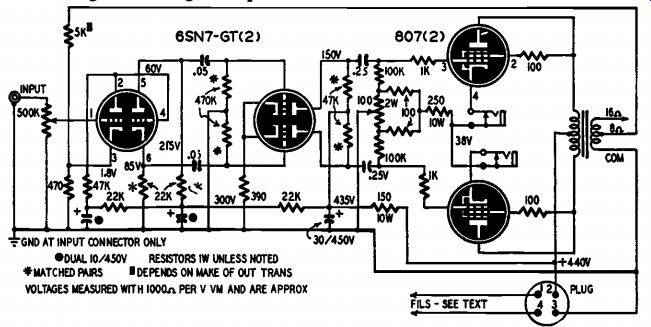
Fig. 1201. Williamson amplifier circuit (Stancor version). Note use
of 807's instead of KT66's and R-C power-supply filtering in first two
stages.
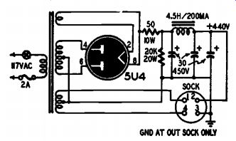
Fig. 1202. Power supply schematic.
The power supply itself is conventional and should cause no trouble. The core of the choke should be perpendicular to the core of the power transformer to reduce the effects of stray magnetic fields.
The layout of the amplifier is not critical, because of the isolated power supply. Be sure the 807's have enough ventilation. The heater circuits should be wired first with twisted pair. These leads should run first to the 807's and then to the 6SN7's. The filament center tap is grounded (instead of grounding one side of the filament line) to minimize hum. To prevent ground loops connect all ground returns to a floating bus and ground the bus to the chassis only at the input connector. Be sure to use insulated mountings for metal-shell decoupling capacitors and connect their negative terminals to the ground bus. Use insulated mountings also for the jacks in the cathode circuits of the 807's.
-----------
Materials for Williamson Amplifier
Resistors: 2-470,000 ohms, (matched), 2-100,- 000 ohms, 1-47,000 ohms, 2-22,000 ohms, 2 22,000 ohms (matched), 1-5,000 ohms, 2 1,000 ohms, 1-470 ohms, 1-390 ohms, 4-100 ohms, 1 watt, 10%; 2-47,000 ohms (matched), 2 watt, 10%; 1-250 ohms, 1-150 ohms, 1 50 ohms, 10 watt, wire-wound; 1-20,000 ohms, 20 watt, wire-wound; 1-500,000-ohm potentiometer, audio taper; 1-100-ohm potentiometer, 2 watts.
Capacitors: (Paper) 2-0.25 uf, 2-0.05 uf, 600 volts. (Electrolytic) 3-30 uf, 475 volts; 1-30 uf, 2-10 uf, 450 volts.
Transformers: 1 Williamson output transformer (Stancor No. A-8054 or equivalent); 1 power transformer: (Stancor PC-8412 or equivalent); 1 filter choke (Stancor C-1411 or equivalent).
Miscellaneous: Tubes: 2-65N7-GT; 2-807; 1 5U4-G. 2 chassis, 11 x 7 x 2 inches; 3 octal sockets; 2-5-prong sockets; 2-4-prong sockets; 2-4-prong plugs; 1-input connector; 2 circuit. opening jacks; 2 insulated plate-cap connectors; I output terminal strip; 1 fuse holder; 1-2-amp fuse; I s.p.s.t. toggle switch; 1 line cord and plug; wire, solder, terminals, hardware.
Materials for Preamplifier:
Resistors: 1-10 megohm; 6-100,000 ohms; 3 22,000 ohms; 1-3,300 ohms; 2-2,200 ohms, I/ watt; 1-10,000 ohms, 1 watt; 3-1-megohm potentiometers.
Capacitors: (Paper) 4-.002 1.af; 2-.02 Ad; 5-.05 0, 600 volts; (Mica or ceramic) 1-200 gef; (Electrolytic) 2-20 Íd, 350 volts; 1-20 gf, 25 volts.
Miscellaneous: 1-12AX7 or 12AY7 tube; 1 12AU7 tube; 2-9-pin miniature tube sockets; chassis, switches, hardware.
------------
All resistors should have a tolerance of 10% or better. It is very important that the starred resistors be matched pairs. If unbalance occurs in the direct-coupled stage it might bias the tube almost to cut off. Unbalance in the phase-inverter circuit will cause unequal drive to the 807's. To get matched pairs take an ohmmeter to your parts distributor and measure resistors until you find two that give the same reading within 10% of the required value. Most distributors will let you do this. It is unnecessary to use a Wheatstone bridge to get two perfectly matched resistors; the ohmmeter will suffice.
A few precautions must be taken to prevent attenuation of the high audio frequencies. Do not use any shielded wire; mount all parts as far above the chassis as possible; keep all leads short; avoid cabling wires together; keep your wiring compact. It is amazing how much difference these small details can make. In this amplifier raising parts above the chassis extended the response 3 kc at the high-frequency end. Don't use a skimpy power transformer. This amplifier uses a size able amount of plate current and the power transformer must be able to deliver. See photo, Fig. 1203, for suggested parts layout of the amplifier and power supply.
Tests and adjustments
To balance the circuit plug a milliammeter into each of the jacks in turn and adjust the 100-ohm, 2-watt balancing potentiometer until both readings are equal at approximately 50 ma each. If your circuit does not balance, check the 807's first.
If the amplifier squeals, reverse the plate leads to the output transformer. This should correct the fault.
The response of the amplifier was checked with a Hewlett-Packard audio oscillator, an RCA audio voltmeter, and a Hewlett-Packard distortion analyzer. The frequency response is superior to broadcast standards and is truly high-fidelity. The unit is free from any inherent circuit noise or microphonics and is very stable. It is well worth the time and trouble put into its construction.
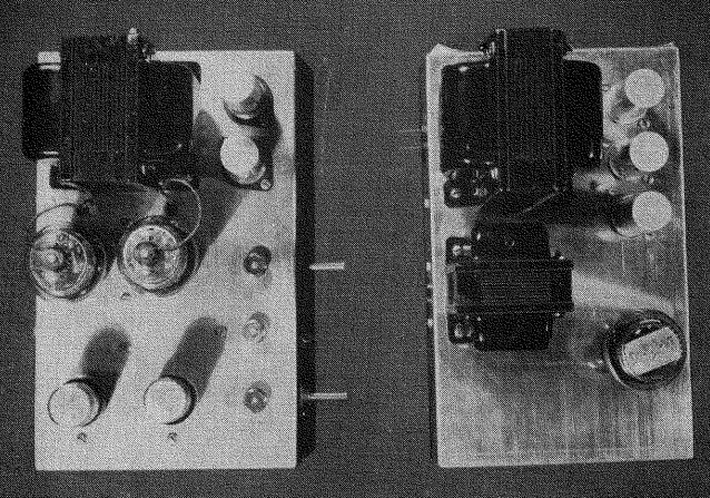
Fig. 1203. Separate amplifier and power-supply chassis reduce hum, allow
uncrowded layouts.
A preamplifier and equalizer should be used with this amplifier to obtain full output and optimum performance when using low-output pickups such as the variable reluctance and some magnetic types. A number of preamplifier-equalizer circuits have been developed by manufacturers and distributors of high-fidelity amplifiers. Some of these include loudness controls and rather elaborate preset equalizer circuits for almost every type of recording characteristic. Others are simpler but equally effective for most applications.
Typical of the simpler circuits is the Heathkit WA-P1 preamplifier equalizer shown in Fig. 1204. A switch selects either of two low-gain inputs for crystal pick-up or tuner, or the high-gain channel for magnetic pick-ups. A two-position turnover switch in the latter channel has positions for 78-r.p.m. and LP recordings. Separate bass and treble controls provide up to 15 db boost or cut at 20 and 20,000 cycles, respectively. Signal voltage input required to develop 1.2 volts output -the approximate value required to drive the amplifier to full output –is 0.2 volt into the low-gain channels and .004 volt for the high-gain input circuit.
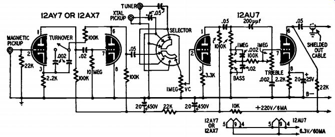
Fig. 1204. Schematic of the Heathkit model WA-PI preamplifier-equalizer
kit. The turn over switch compensates for the different frequency characteristics
used in 78-r.p.m. and LP recordings. Bass and treble controls give flat
response in mid-positions, 15 db boost or cut at opposite ends. 12AY7
is a low-microphonic type.
Other preamplifier circuits can be used with the Williamson amplifier provided the amplifier input requirements are kept in mind. The circuit shown in Fig. 1204 has the advantage of simplicity.