ALTHOUGH this amplifier departs from the conventional in many respects, it has no fancy hard-to-adjust features. A frequency run with a Hewlett-Packard oscillator and a G-E VU panel shows it to be flat within 1-1/2 db, 20 to 20,000 cycles. The output transformer governs the frequency response, and that depends on what the pocketbook will stand. Fig. 1701 is a top-side photo and Fig. 1702 is the schematic of the amplifier.
Except for the output tubes, all stages use miniatures. The phase inverter stage--a 6J6 duo-triode--is cathode-coupled; so you don't have to juggle resistors. The only transformer in the amplifier is in the output stage. The final tubes are driven by a pair of 6C4's used as cathode followers for low driving impedance and as a good way to adjust the balance of the final stages. The 6AG5's are triode-connected to make the whole amplifier triodes from input to output! That should satisfy even the most rabid "triodes-are-best" boys.
The first 6J6 is a preamplifier to drive the phase inverter and also an electronic bass-boost stage. The mathematics of the bass-boost stage get rather complicated, but the values shown make it perform well.
The second 6J6 dual triode is the cathode-coupled phase inverter.
The grid of one section is fed the audio signal, and the other grid is grounded. The cathodes, being tied together, work in unison. Both plates also vary as the input signal varies, but the signal outputs are 180° out of phase. It's a neat scheme that works nicely. Since the 6j6 is a high-mu triode, good stability and low hum level are important.
The phase inverter stage must be shielded with a miniature spring loaded tube shield to minimize microphonics which 6J6's often develop. The a.c. circuits should be carefully laid out to keep hum
pickup low. With these precautions the 6J6 performs well. This type of phase inverter shows no aging effects, as is often the case with other inverter circuits.
The next stage uses two 6AG5's, triode-connected, to drive the 6C4 cathode followers. The fixed bias for the final tubes is fed through the cathode loads of 6C4's; and, by varying a portion of this voltage on the 6C4 grids, the bias can be adjusted so the signal in the final output tubes is balanced.
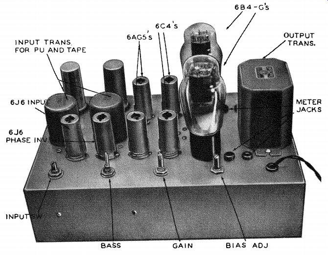
Fig. 1701. Photo of the amplifier. The two input transformers on the
left are for a tape recorder and low-impedance pickup. They do not appear
in the schematic diagram.
In the final stage either 6B4-G's or 6A5-G's can be used. The 6A5-G is preferable because the cathode-type construction further reduces hum.
Cathode bias can be used, but the fixed bias gives increased output and keeps the bias voltage constant under all plate conditions. This bias voltage is stabilized by an 0D3 regulator tube.
For an output transformer you can take your choice. If you want the ultimate in performance, use one of the best quality transformers, so long as it loads the tubes with 3,000 ohms.
The physical layout of the amplifier can take almost any form, provided the usual wiring precautions are observed. Run the a.c. wiring close to the chassis and so that no ground loops are formed. A common-ground bus is better than the usual chassis ground.
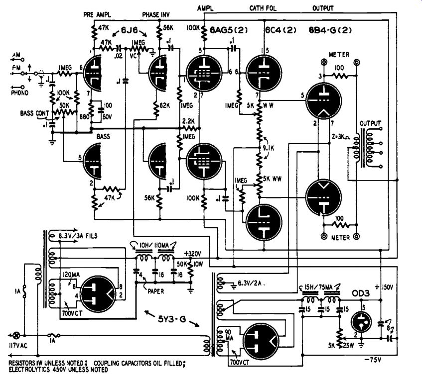
Fig. 1702. The schematic of the all-triode amplifier. Input operates
at low level and has high gain.
While separate chassis were used for the amplifier and for the two power supplies, both could be on the same chassis if the power trans formers are mounted away from the input stages.
------------
Materials for Amplifier:
Resistors: 2-100, 1-680, 1-2,200, 2-9,100, 4-47,000, 2-56,000, 1-62,000, 4-100,000 ohm, 5-1 megohm, 1 watt; 2-5,000, 1-50,000 ohm, 1-1 megohm potentiometers; 1-5,000 ohm, 25 watt; 1-50,000 ohm, 50 watt.
Capacitors: 2-0.1 uf, 400 volt, paper; 1-.02, 5-0.1 uf oil filled; 1-4 uf, 600 volt, paper; 2-8, 5-16 uf, 450 volt, 1-100 uf, 50 volt, electrolytic.
Miscellaneous: 1-350-0-350 volt, 90 ma, 1 350-0-350 volt, 120-ma power transformers with filament windings; 2-10 h, 110 ma, 2 15 h, 75 ma chokes; 1-output transformer, 3,000 ohm primary; 2-6J6, 2-6AG5, 2-684 G or 6A5-G, 2-5Y3-GT, 1-003 tubes with sockets; 2-1.amp fuses and holders; chassis, hookup wire, switches, assorted hardware.