THUS far we have assumed that the desirable frequency response is absolutely flat-that all frequencies in the audio spectrum must be reproduced uniformly. Now we come to cases where correction has to be made for various non-uniformities that come to light in audio systems.
Why equalizers are needed
For example, due to its own mechanical frequency response, a disc cutter head may not give an exactly uniform cut at all frequencies for the electrical power supplied to it. Equalization is necessary so that, where its response is weak mechanically, more electrical power is supplied to it. The result is that a uniform amplitude of cut is made at all frequencies for a uniform electrical input to the system (Fig. 701 ). Because it has no moving parts, a tape recording head is inherently much more linear in its frequency response than a disc cutter head. However, its dimensions control the magnetic field it produces in the tape and this, together with the velocity of the tape and losses in the magnetic core of the head, affect the possible frequency response.
Disc pickups and tape playback heads also produce their own individual frequency responses. The ideal, of course, is to select a pickup that has (as nearly as possible) a flat frequency response and does not need equalization for its mechanical characteristics.
However, if a pickup is as good as can be made but a perfectly flat response is needed for some reason, it may be necessary to equalize for the slight deficiencies that remain in the pickup.
With a playback head there is definite need for equalization in all cases because the frequency response is rather like that shown in Fig. 702. This can be explained in terms of the overall characteristic of the magnetic recording system.
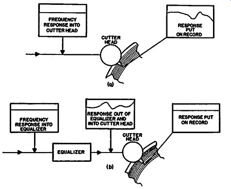
Fig. 701. Equalizer compensates for the response deviatio11 of a cutter
head.
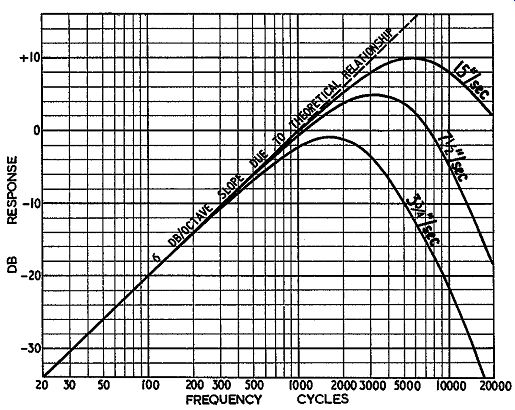
Fig. 702. Typical response curves of a tape playback head, using a constant-magnetic-density
tape at different speeds.
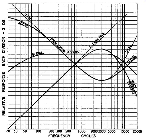
Fig. 703. Playback equalization for a fiat overall frequency response
over an acceptable range.
If a constant current, at different frequencies, is fed to the re cording head, the amplitude of magnetization on the tape will be constant. This means that the maximum amplitude, just where saturation commences, will correspond with the same current in the recording head at all frequencies. This assumes that the losses in the recording head are uniform. In practice they are not, so these will need to be equalized in recording.
On playback, the output from the playback head is proportional to the rate at which the magnetic field fluctuates or to the intensity of magnetization at any particular frequency. But with different frequencies it will be proportional to the frequency, assuming the same intensity. Thus the playback head will produce a response with a 6-db-per-octave rise because doubling the frequency doubles the rate at which the field fluctuates.
However there is limit to this response, due to the physical dimensions of the air gap in the head. When these become comparable with the wavelength of the magnetization along the tape, high-frequency loss sets in. So the overall characteristic (Fig. 702) is a rising response at 6 db per octave until the high-frequency loss begins to pull it down. It reaches a maximum somewhere between 2,000 and 5,000 Hz (according to individual head design and the speed of tape used) and then falls off very sharply.
To get a response to a higher frequency than that naturally produced by the head, equalization is again necessary (Fig. 703). Equalization may also be necessary for microphones or speakers, each of which can have deficiencies in frequency response which could be compensated for electrically. However, the "progress of the art", as it is called, has shown that this is not really a good policy. The best approach is to design a microphone and speaker to have a response as flat as possible.
Equalization not always the answer
The author recalls a microphone in which the approach used was to eliminate all resonances except one major one. This was achieved by cutting holes in the framework so that there was only one large cavity which was tuned by the mechanical mass of the diaphragm. The result was a microphone with a single peak, about 30 db high, in the region of 500 Hz. This microphone was operated with a built-in equalizer that produced a corresponding "hole" in the response at the same frequency.
Its overall response turned out to be the closest to flat that had been achieved in any dynamic type microphone until that date.
From the viewpoint of frequency response alone, it would still be an extremely good microphone. However, its performance left something to be desired, since the electrical equalization could not compensate for the deficiencies of the resonance in handling transients.
This can be illustrated by Fig. 704. When a 500-cycle tone first strikes the microphone mechanically, it will take time to build up to its maximum amplitude, due to the high Q of the mechanical resonant circuit-about 30. This means it will take about 30 Hz to reach 0.637 of its ultimate amplitude. Similar buildup takes place in the equalization circuit, due to the high electrical Q. It will take about 30 Hz of the 500-cycle tone to get 0.637 of the ultimate absorption effect of the circuit.
Now if the pulse stimulus came at a point between the micro phone and equalizer, the two would neutralize and produce an output that is a replica of the input. But the fact that the feed starts from the mechanical side of the microphone and goes through that resonance and then the output from that is fed to the input of the electrical equalizer, means that the electrical equalizer does not have the same square-frontage pulse to handle that the microphone does. For this reason the absorption effect of the electrical equalization cannot start operating until the mechanical resonance of the microphone has started to build up.
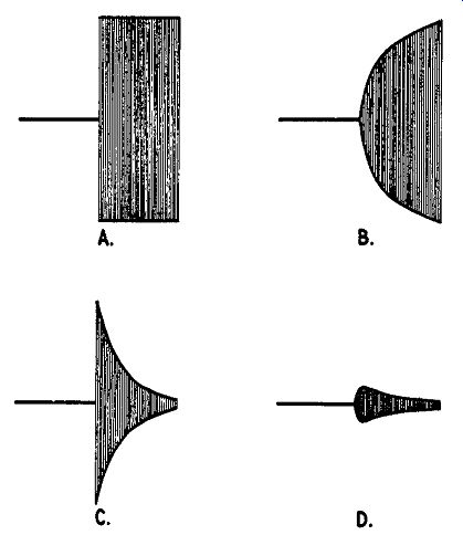
Fig. 704. Transducers needing excessive equalization should be avoided:
a--acoustic input wave to the microphone discussed in text; b--electrical
response to wave a; c--response of equalizer network to wave a; d--overall
response, which does not restore shape of a.
The overall output will show a kind of ring on the front edge of the 500-cycle tone before electrical equalization manages to control it. Of course a square pulse of 500-cycle tones is not the kind of signal that happens very often in program material. But other kinds of transients are, and the effect of this arrangement is to color any transient with a kind of 500-cycle ring effect.
The sound of a door shutting, picked up by this microphone, is as if all the panels in the door, as well as most of the panels in the room, were tuned to mechanical resonance at 500 Hz. If you don't hear the noise of the door live-only as reproduced over the microphone, this does not perhaps sound impossible but, when other sounds all seem to have the same resonance, it gives a general coloration to the reproduction. This is quite noticeable even though the overall response of the microphone is perfectly flat when a continuous tone of different frequencies is used for making the measurements.
For this reason all kinds of transducers; microphones, loud speakers, cutters and pickups are, as far as possible, designed to have a flat frequency response in themselves so as not to need electrical equalization.
Another place where electrical equalization may be necessary is in radio transmission and reception. Here, again, the ideal arrangement is to arrange for the various radio circuits to have a flat-topped bandpass characteristic so that demodulation of the program material gives a uniform frequency response without the necessity for any equalization. However, the practical consideration of reducing noise caused by various forms of interference sometimes dictates that the radio response has to be rolled off somewhat toward the extremes of the passband.
This can sometimes be helped by using electrical equalization to bring back some of the lost highs. However, unless a radio circuit is used that discriminates against the various noise or interference components (as well as losing some of the higher frequencies) restoration of the high frequencies in the audio circuit will equally restore the interference! This discussion, however, is somewhat outside the scope of an audio guide.
Phono and tape equalization
Another cause for equalization-and in modern audio practice the principal one-is to achieve satisfactory operating conditions for the recording medium used, whether disc or tape.
Taking disc first and using lateral cut (common practice these days), there are two bases for standardization: the amplitude of the cut-that is, the width between the maximum excursion from side to side of the groove (Fig. 705), and the velocity of the cut--the maximum rate at which the stylus moves in cutting the groove.
As the majority of pickups utilize a velocity principle (the electrical output from the pickup is proportional to the rate at which stylus moves) this standard of reference holds most favor. It is a useful reference also because it yields a convenient method of calibrating the grooves actually cut on the disc. From these considerations it would be convenient to use a constant velocity cut in which the same electrical input would produce the same maximum velocity of stylus movement at all frequencies. But this will mean that the amplitude of excursion will be inversely proportional to frequency. See Fig. 706.
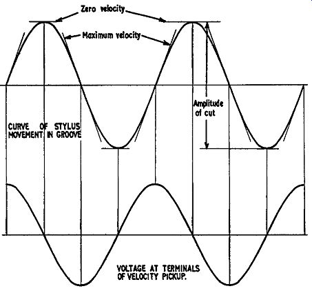
Fig. 705. Essential features of stylus movement in a groove for velocity
type pickups and recording heads.
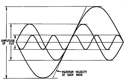
Fig. 706. Grooves of different frequencies are superimposed to show
relation between velocity and amplitude.
To use some practical figures, if the excursion for maximum output at 20,000 Hz is 1/10,000 inch-a very small excursion--the movement at 20 Hz for the same electrical output would be 1,000 times this, or 1/10 inch. Obviously it is not possible to pack in 100 grooves to the inch (or even more) if each groove is going to make an excursion approaching 1/10 inch.
The grooves would overlap several times over.
So, in the interest of economy in groove spacing, it is necessary to limit the excursion at the lower frequencies. This is the reason for the low-frequency rolloff in recording. By limiting the constant-velocity principle to, say, 500 Hz and then changing below this frequency to a constant amplitude, the maximum excursion, using the same hypothesis, is restricted to about 1/400 inch. On this basis it will be readily possible to exceed 100 grooves per inch.
But that is not all there is to the problem. As with input stages, we have a dynamic-range problem and this hits us at the high-frequency end. Using the same assumed basis of a maximum amplitude of 1/10,000 inch at 20,000 Hz, this will be come 1/5,000 inch at 10,000 Hz (a more usual maximum upper limit although some recordings maintain appreciable output up to 15,000 Hz). Taking the maximum excursion as 1/5,000 inch and the dynamic range as 60 db, the minimum excursion at 10,000 Hz will be 1/5,000,000 inch. This is so very small that noise will drown out signal in this region.
For this reason it is desirable to increase the velocity or excursion of the stylus at higher frequencies. To assist in this, a reversal from the constant-velocity principle to constant amplitude again takes place in the region of 2,000 Hz. For the RIAA curve this changeover takes place at 2,120 Hz.
Different authorities have come to slightly different conclusions as to which is the best compromise in achieving a good working characteristic, but the principles governing the decision are the same in all instances.
Using tape as a recording medium, constant amplitude is the obvious limitation. Saturation effect limits the maximum amplitude that can be put on the tape at any specific frequency.
The principal modifications made to the recording characteristic on tape are due to the excessive high-frequency losses in evitable in any playback head and also the inherent restricted dynamic range of tape. To get an effectively low background noise, it is desirable to operate with as little "headroom" as possible between the maximum signal and saturation point at all frequencies.
As most of the energy is concentrated in the mid-range and most of the noise in the higher frequencies, it is good to pre emphasize the higher frequencies so that their energy level is nearer that of the mid-range on recording. This gives them a better margin above the background noise level in this region (Fig. 707). At the same time this will help overcome high-frequency loss in the playback head.
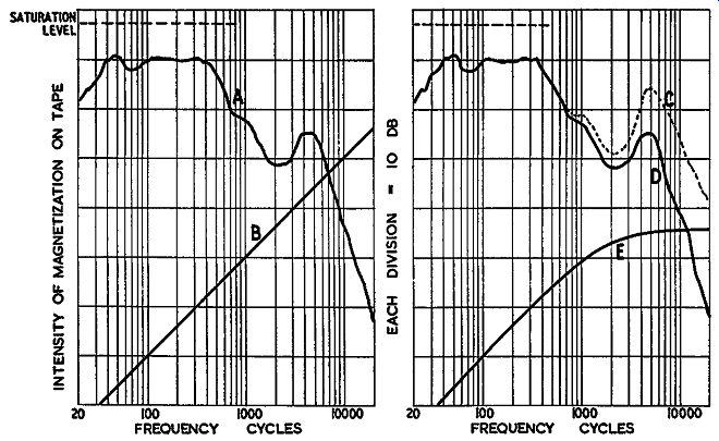
Fig. 707. How pre-emphasis helps: Curve A is a typical energy distribution
curve for program material; curve B is the noise energy distribution;
curve C shows energy distribution in program with pre-emphasis. De-emphasis
on playback gives curve D, which is the same as curve A, but noise changes
to curve E.
Standards
Where an entire system is being used by the same individual for recording and playback, it is not very important whether the exact record characteristic and playback characteristic con form to any particular response, provided the overall response from the input to the recorder to the output from the playback is flat. A variation of a few db in the response on the actual recording does not matter, provided the overall result comes out right. But when recordings are made on one recorder and played back on another, it is highly desirable to have a standard of recording and playback characteristics so that any recorder will produce a recording which, reproduced on any play back system, will come out flat. This is the reason for establishing standards in both disc and tape recording.
While it is easy to say what the standard response should be, the question arises of how we can establish that a recording satisfactorily follows a specified response.
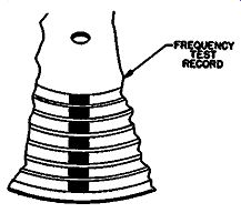
Fig. 708. Light pattern seen across a test-frequency disc, when each
frequency band is recorded at the same velocity.
In the case of disc recording, this is relatively simple. A visual inspection under a point source of light will readily show this (Fig. 708). If the grooves are unmodulated, parallel concentric grooves, the point source of light will give a narrow line down the record as it reflects in each consecutive groove. But when the grooves are modulated, the angle (due to the velocity of modulation in the middle of excursion) causes an extended band of reflected light (Fig. 709).
So the width of a band of light reflected from a point source depends on the maximum velocity of modulation at this point.
This forms a very convenient means of examining a recording and estimating the response with considerable precision.
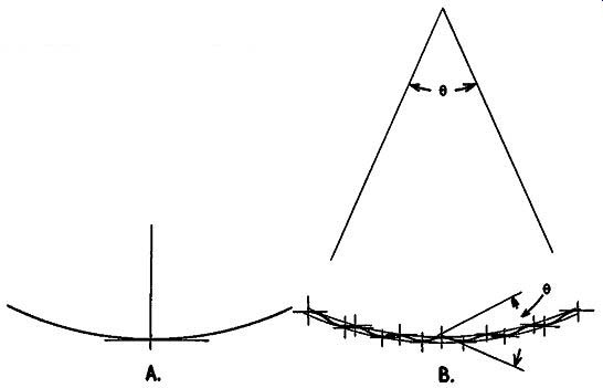
Fig. 709. a--with an unmodulated groove, light is reflected from just
one point. b--when groove is modulated, reflection occurs over an angle
limited by the angle between the maximum velocity points in opposite directions.
A standard-frequency record can be readily made for testing pickups and record players by recording bands at different frequencies and adjusting the amplitude of recording so the response is uniform or follows the desired playback characteristic.
If the cutter head is not accurate, adjustments can be made experimentally to produce a uniform resultant recording in spite of the variation in integrity of the cutter.
Disc "standards"
This sounds so simple that it must be too good to be true! This proves to be the case at the high-frequency end. The same pickups tested on different recordings, each of which look identical under this method of inspection, will give quite different frequency response characteristics. The results may even be contradictory.
This is so because the performance of a pickup depends, not only on the mass and compliance and various mechanical features of the pickup itself, but also on the compliance of the record material where the stylus rides in the groove. ·when the record should move the stylus very rapidly at high frequencies, the groove walls "give" a little bit instead of moving the stylus as they should. The amount by which the walls give will vary according to the characteristics of individual pickups and the material of which the disc is made.
The characteristics we see when we examine the record under a point-source light beam only indicate what the grooves are when they are static. It does not indicate the shape they take when a stylus rides in them and, of course, that shape may vary according to the pickup to which the stylus is fixed.
This situation in disc recording is still in a somewhat unsatisfactory state. Of course, disc materials could be standardized, but they are not. Not even test records are standardized for this purpose. Even if all test records were pressed in a uniform material so they gave identical results with different pickups, we would still be faced with the fact that discs carrying recordings of program material are not necessarily pressed of material identical to the test recording and, therefore, the frequency response of the pickup will not necessarily conform to the results shown under test conditions.
What all of this says is that, while different materials are used for making disc pressings, different pickups will show contradictory differences between the quality of various recordings, as regards frequency response. Comparing disc no. 1 with disc no. 2 on pickup A, may show that disc no. 1 has a high-frequency peak while disc no. 2 gives a very flat frequency response. On the other hand, using pickup B may well show just the reverse due to the fact that the respective compliances of the alternate records happen to suit the mechanical characteristics of the alternate pickups. But using each with the opposite kind produces a peak--or it might equally well introduce an excessive high-frequency loss. This is something that is difficult to predict because so many variable factors are involved.
Unfortunately, manufacturers of reasonably high-quality pick ups publish characteristics for their pickups, taken with the "standard test recordings" which happen to give the best-looking response. This is by no means "cheating." When there is no standard record material, who is to say which is the right recording? All of them show the right light patterns. A typical set of curves is shown in Fig. 710. The deviation at the high-frequency end from 10,000 to 15,000 Hz is by no means a matter of a few db it can be as much as 10 db or even more between individual re cording and pickup combinations.
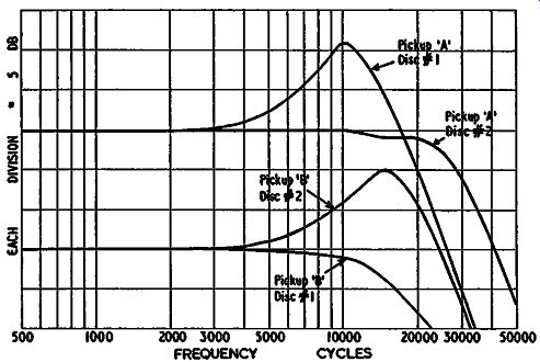
Fig. 710. A typical set of curves taken with two different pick-ups
on two different test discs, both having accurate characteristics.
Tape standards
With tape, the situation does seem to be a little better although at the start it may seem to be not so good. There is no convenient means of looking at the response recorded on the tape. We are entirely dependent on exploring the response by means of a play back head. However, careful comparison of results, using different playback heads with varying widths of air gap, and giving different theoretical frequency responses, shows that the results are reason ably consistent with mathematical prediction. This means that we can assume that the recorded characteristic produced on a test tape is within 1, or at the most 2, db of the specified response.
While it is possible, by means of light patterns, to check a disc recorded response even closer than this, the tape does not suffer from the same compliance problem that the disc does. The play back head can be measured on any test tape and the results are much nearer to being consistent than they are with pickups on a test disc, particularly at the high-frequency end.
Methods of equalization Having obtained standards for measurement, the next step is to provide equalization in audio equipment to meet their requirements.
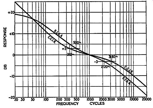
Fig. 711. The two main standards used for disc recording today. Curves
are the required playback characteristics, using an ideal velocity pickup.
For disc recording many standard characteristics have been used, all of which differ slightly. This situation arose because each disc manufacturer developed his own standard recording characteristic, based on the same fundamental problems but arriving at slightly different variations of a similar conclusion. To reproduce all discs with exactly flat frequency response, a preamplifier needs to have somewhere in the region of 10 equalization characteristics.
However, the effort toward standardization is progressing and there are two main standards which come close to fulfilling practically all of the modern requirements in disc equalization.
One of these is that issued by the Recording Industry Association of America (RIAA) and accepted as standard by all of the American record companies. The other standard is known as the CCIR, which stands for the French equivalent of International Radio Consultative Committee. While almost all American recordings now conform to the RIAA curve, foreign, particularly European recordings, conform to the CCIR characteristic. It is better, of course, to have just two standards than about a dozen.
These two characteristics are shown in Fig. 711.
For tape recording two standards (Fig. 712) also exist, one set by the NARTB (National Association of Radio & Television Broadcasters) which is applicable to all American pre-recorded tapes and the other established by the CCIR applicable to most of the foreign recorded tapes.
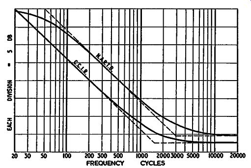
Fig. 712. The two standards for tape recording (7½ inches per second).
Curves are idealized playback characteristics.
We now come, in considering equalizers, to the part that is more strictly audio-how they are made, the kinds of circuits and their relative merits.
Any equalizer involves a loss in gain. This is because its gain at different frequencies is not uniform, to provide the equalization characteristic. Most of the equalization characteristics provide a low-frequency boost to compensate for the rolloff that occurs during recording. In disc recording, this is to produce an accept able amplitude of excursion at low frequencies.
In tape recording it is due to the fact that the playback head operates as a "velocity" device (more strictly it is a "change of magnetization" device) while the recording head is a constant current or, more strictly, a constant-magnetic-amplitude arrangement.
Whichever way you look at it, the result is a system that needs bass boost on playback. This means that frequencies below 1,000 Hz need amplifying more than frequencies at or above that.
We are interested in 1,000 Hz because it is the frequency at which the gain of a system is usually measured or specified. Most of the energy in program material occurs in the region from 400 or 600 to 1,000 Hz, hence the apparent loudness is dependent upon the amplification in this frequency range-not on the amplification below 400 Hz or that above, say, 2,000. However, the fact that, due to the equalization, a greater amount of gain is required at the extreme low frequencies, of say, 50 Hz means that some gain must be sacrificed in the 1,000 cycle region to have the extra gain available at lower frequencies.
Different methods of equalization involve different amounts of loss of gain. Other questions that come into the decision as to which kind of equalizer to use are: the amount of distortion the overall arrangement may introduce into the system; and the effect of the method on the dynamic range available-that is, how much "room" there is in the overall system between the noise level and the maximum level the system will handle. Other important considerations are the accuracy of the equalization characteristic-how closely it adheres to the ideal response required of the system, and also the stability of the accuracy. In other words, how much the frequency response provided by the equalization depends upon tube characteristics or other parameters-whether the equalization is likely to become inaccurate if the gain of a tube changes, for example.
General philosophy
These are the performance considerations. On the practical side comes the question of where in the circuit to put the various "bits" of equalization necessary. The logical thing, to make a system adaptable and foolproof, is to associate each piece of equalization with the particular part of the system for which it is in tended (Fig. 713). For example, equalization for a disc cutter should be as close to the cutter as possible. If it is inserted in a main power amplifier that supplies the cutter, this means that the amplifier is not suit able for any other purpose because the frequency response has been tailored to offset the deficiencies of a particular cutter.
In the playback end it would be ideal to associate the equalization for a pickup directly with the pickup. Certainly the equalization for a pickup should not be used when playing program material from a radio tuner, for example, which should not require any equalization if the tuner is well engineered. This means that the logical place to put the equalization for a pickup is right in the pickup circuit, out in front of the preamplifier, and then to use a preamplifier whose response is absolutely flat.
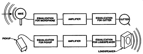
Fig. 713. Proper equalization associates each correction network directly
with the component for which it serves.
Passive equalizer
Such a unit is called a passive equalizer. The difficulty with this arrangement is that many modern pickups, especially those used for playing microgroove recordings, give such small outputs that the signal-to-noise ratio is very little better than that obtained from a good high-gain preamplifier. Passing the program immediately through an equalizer will cause an attenuation of some 20 db in the signal level, which means that the amplifier will have to pick it up from a point 20 db lower in level. Consequently, the signal-to-noise ratio will be made worse by putting the equalizer directly against the pickup. This is the reason for incorporating equalizers inside preamplifiers, somewhere between stages.
Having decided that the so-called passive equalizer, placed right against the pickup, is not ideal because of the restriction of dynamic range due to noise, the next question is the best kind of equalizer to use in a preamplifier circuit.
Direct type following triode
The most obvious uses a straightforward equalization of a type similar to the passive equalizer but puts it between stages (Fig. 714). The difference in method here depends on whether the stage the equalizer follows is a triode or pentode.
All basic phono equalizers fall into the general pattern of Fig. 715 to provide a bass boost and a high-frequency rolloff. Tape equalizers omit the high-frequency rolloff and may have a high boost instead because of the loss in the playback head. The equalizers, of course, differ in values to suit the individual characteristics required and the circuit into which they are connected.
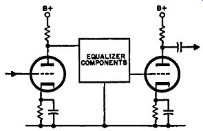
Fig. 714. Any interstage equalization circuit is basically a three-terminal
network.
In the interest of providing a minimum loss of gain, where no high-frequency boost is needed, R1 can be the plate circuit ac resistance of the preceding stage, instead of inserting an additional resistance for this purpose. In designing such an equalizer, the plate circuit resistance of the preceding stage must not be over looked. If this is not taken into account, the characteristic achieved will not conform to the specification intended.
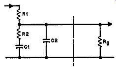
Fig. 715. Basic equalization circuit for phono playback characteristics.
R1 and R2 determine the amount of lift in the bass. C1 fixes the point
of bass lift in frequency. Rg must be taken into account, although not
part of the network. C2 provides the treble rolloff.
However, if this circuit follows a triode input stage, this means that, at 1,000 Hz (and assuming a 20-db bass boost) the plate of the preceding stage will be operating into a dynamic load about one-tenth of its plate resistance. This almost vertical load line for a triode tube produces excessive second-harmonic distortion.
For this reason it is essential to build up the source resistance R1 with an actual resistance value as well as using the plate resistance of the tube, which should be a smaller part of it (Fig. 716). In this way the operating condition of the triode is protected although more gain is lost than would be without the additional resistance. A triode has the advantage that the inherent distortion is low, provided these precautionary measures are met. However, the fact that the loss is larger than basically necessary for the kind of circuit used means that the attenuation in the equalizer is greater. If the equalizer immediately follows the first stage, the signal level at the second-stage grid will be only a few db greater than that at the input to the preamplifier. This means that the equalization stage can contribute a noticeable proportion of noise to the output.
This deficiency can be overcome by using two stages of amplification before going through the equalizer, but this usually involves additional switching since (in the interest of economy) it will be desirable to use the same stages for radio and other inputs that do not require equalization.
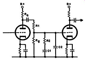
Fig. 716. The circuit applied between two triode stages. The essential
components are numbered to correspond with Fig. 715, except that R1 of
Fig. 715 corresponds to R1 in series with R_Q both in parallel with R_g
here.
When R1 is used, the accuracy of this kind of equalization circuit is unsurpassed by any. Its stability is also good because any changes in tube parameters will not materially affect the equalization characteristic.
Following pentode If the first stage of a preamplifier is a pentode (Fig. 717), the additional resistor R1 is not necessary in the equalization circuit.
The basic source resistance presented by the pentode stage is principally the plate-coupling resistor because the pentode's plate resistance is usually much higher than the coupling resistor.
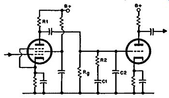
Fig. 717. The circuit applied following a pentode stage. R1 must l,e
combined in parallel with R. and the plate resistance of the tube to
get the theoretical value of Fig. 715.
As a pentode stage does not introduce appreciably greater distortion by using a lower value of plate load, the equalization characteristic can be achieved with a value of R2 in the region of one-ninth of the combined parallel resistance of the plate-coupling and grid resistors. This will give the necessary 20-db boost with a minimum of loss.
The extra gain provided by a pentode will improve the signal to-noise ratio. The accuracy of frequency response and particularly stability of the accuracy are perhaps not quite as good as in the triode stage, especially if a high value of plate-coupling resistor is used. Under this condition the plate resistance of the pentode may only be two or three times the value of plate-coupling resistor used and fluctuation with operating conditions can modify the apparent source resistor value by a perceptible degree.
The principal reason for rejecting the pentode stage input, though, is the matter of distortion--the fact that the distortion characteristics of a pentode, even on an input stage, are inherently higher than those of a triode. A secondary reason is that a pentode stage introduces a higher noise level than a triode. This does not invalidate the method of equalization for itself, but because of consideration of the tube type for an input stage.
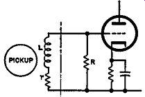
Fig. 718. Sometimes high-frequency roll off can be achieved by selecting
the input resistor R to combine with the electrical characteristics of
the pickup, represented here by r and L.
Separate sections
The foregoing equalization circuits have grouped all of the equalization characteristics into one network. This is not necessary. Under suitable circumstances, the functions can be separated.
In fact, for disc equalization, it is sometimes advantageous to put the high-frequency rolloff somewhat earlier in the circuit. It can help out on noise problems by restricting the frequency band in the area where noise is generated.
One very convenient way of doing this can be used if the pickup happens to be inductive. For example, many magnetic pickups have considerable inductance. By loading the input with a suit able resistance value (Fig. 718), the correct high-frequency roll-off can be achieved right in the input circuit. Then it only re mains to use the regular equalization network to produce the low-frequency boost.
So much for the direct type equalization circuits, all of which in general have a similar gain loss. The distortion is dependent upon the operating condition chosen; the dynamic range upon the position in the circuit where the equalizer is inserted. And the stability of accuracy to the required characteristic is good compared to most other circuits, being dependent only upon variation in source plate resistance, where this is of a magnitude that can affect the response of the circuit.
Feedback type
Feedback circuits have achieved a considerable degree of popularity, one reason being an alleged improvement in distortion.
We say alleged because, under well-designed conditions, the direct-equalization method can achieve extremely low distortion and even the feedback type is not free from possible forms of distortion. A poorly-designed feedback type will give more distortion than a non-feedback type that has been well-designed. With care in the design, the feedback type can achieve certain advantages in its handling of distortion. It can substantially reduce the more objectionable form of distortion-IM-although it may not be so effective against the lesser evil-harmonic distortion.
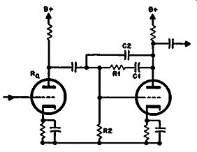
Fig. 719. A feedback type applied between two triode stages. Design
of this circuit runs into serious difficulties. See Fig. 720.
Single triode stage
Fig. 719 is a feedback circuit over a single triode stage. The advantage of feeding back over a single stage is that only the feed back network contributes to the response characteristic of the loop gain around the stage. This means (a) that the characteristic is easier to calculate and (b) that it will achieve greater stability in accuracy for the intended characteristic than a two stage feedback type.
There is usually some problem with this type in achieving bass boost. This method results in a gain loss equal to the amount of boost required and thus is exactly similar to straight forward equalization. High-frequency rolloff, however, using feedback over a single triode stage, is almost impossible to achieve since 20 db of the gain in the stage has already been sacrificed for low-frequency boost.
The overall loop gain of the stage is not likely to be more than 50, even if a high-gain tube is used. Actually, it is practically impossible to achieve a gain this high, due to the loading of the feedback circuit on the plate of the tube. For this reason, even using a high-slope tube, we are lucky if we achieve a gain of 20 or 30, which is only 6 or 10 db more than the required bass boost.
This means we have available only some 6-10 db additional roll off for the high-frequency end. Rolloff further than this must then be provided in another circuit.
While the loss in the feedback stage itself is the same as in other circuits, it can result in additional loss for the preceding stage. More resistors may be needed to get a satisfactory degree of feedback without losing stage gain. The plate resistance of the preceding stage normally loads the grid circuit resistance and thus requires low values of feedback resistors (Fig. 720).
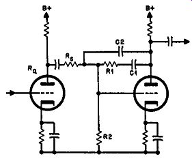
Fig. 720. To get an adequate amount of gain, and at the same time achieve
the necessary range of feedback, the resistor R, in needed. The effective
value of R2 is now the resistor of that number, paralleled by R, and
R. in series. Without R., R0 shunts the value of R2 to a value too low
for a practical design. The component numbers in this diagram indicate
an approximate correspondence with the same numbers in Fig. 715.
This circuit suffers from the same deficiencies as regards potential signal-to-noise ratio as the placing of the straight-forward equalizer after a single triode stage. If a high-gain triode is used, it may be difficult to get a sufficiently high plate-load value to avoid causing some distortion. The feedback may be insufficient to bring the distortion thus produced back to the same order as that achieved in a straight amplifier, using better load values for the tubes.
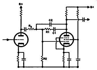
Fig. 721. Applying the same circuit to a pentode stage gets better results,
as far as achieving the desired characteristic is concerned.
Single pentode stage
Some of these problems can be overcome by using single-stage feedback over a pentode tube (Fig. 721). The higher gain permits more suitable resistor values for the feedback with less loss of gain. Also the higher loop gain provided by a pentode means that the high-frequency rolloff can be successfully achieved by the capacitor provided for the purpose, without having to resort to additional rolloff elsewhere in the circuit.
However, a pentode, especially operating as a second-stage amplifier, will produce more distortion than a triode stage.
While the feedback will reduce the distortion in the 1,000-cycle region, it will not do so at the low-frequency end. In comparison, the straightforward equalizer, especially following a previous triode stage, will produce less distortion at the low-frequency end and, if anything, only slightly more in the middle of the band.
Thus the pentode feedback stage is liable to produce some distortion in extreme low frequencies. This would normally introduce IM distortion as well as the natural harmonics of the low frequency. However, the feedback arrangement does produce approximately 20-db reduction in the resultant IM distortion.
The residual harmonic distortion is probably of little importance since the ear is unable to detect small quantities of harmonic distortion as a separate entity. The principal reason for the importance of harmonic distortion in amplifiers is not the harmonics generated so much as the equivalent IM distortion that usually goes along with it.
Stability of accuracy for the desired characteristic is not quite so good as the type using a single triode stage. The gain of a pentode is more susceptible to change with operating conditions than is a triode and the amount of bass boost is definitely dependent upon the overall loop gain. This, in turn, depends upon the precise gain achieved by the pentode.
Two triode stages
The final type we shall consider here utilizes feedback over two stages of amplification. If these stages are direct-coupled, the same design approach can be used as for a single stage.
However, direct coupling involves problems due to the de potential differences involved. While it may sometimes be convenient to use direct coupling between a voltage amplifier and a phase inverter, it is not usually convenient to do this between two voltage-amplifier stages, as would be used for providing two-stage feedback equalization.
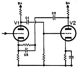
Fig. 722. The application of feedback over two triode stages. C1 and
C2, with their respective associated resistance values, and the overall
feedback designed into the circuit determine bass boost, while C1 affects
high-frequency rolloff.
The "forward" coupling capacitor C1 in Fig. 722 has to be taken into account in the design consideration. The method of design consists of considering ( 1) the loop gain characteristic and (2) the effect that closing the loop will have on the overall loop gain characteristic; this will then modify (3) the inverted characteristic of the feedback circuit (Fig. 723).
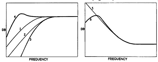
Fig. 723. Design approach for the circuit of Fig. 722: Curves 1 and
2 show the rolloff achieved by C1 and C2, respectively. Curve 3 is the
combined loop gain response, without counting the effect of feedback
(measuring the output at the left hand of C2, with a large capacitor
bypassing the cathode of VI). Curve 4 is the loop gain response when
feedback is added (by removing the bypass). Curve 5 is the response on
the right-hand side of C2 compared to that on its left (as flat). Curve
6 ts the overall response, due to the fact that the curve at the left
of C2 is not flat, but as at Curve 4.
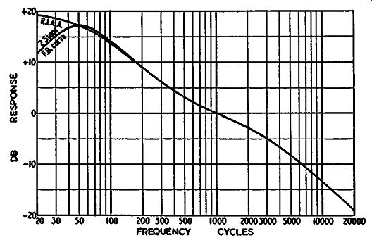
Fig. 724. Best approach to the RIAA curve obtainable by the methods
of Figs. 722 and 723.
From here on, there are two approaches. First, the coupling capacitor C1 in the forward part of the amplifier can be so large as to place its effect on frequency response well below the region through which equalization is required. As equalization is usually at least down to 50 Hz, and maybe even lower in some instances, the effective coupling capacitor should maintain the response down to the region of probably between 1 and 5 Hz. Even then it may invalidate the response by the phase shift it introduces into the overall gain in a way that will not occur where this coupling capacitor can be avoided.
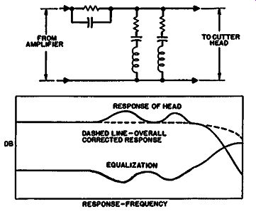
Fig. 725. A typical equalization circuit to correct the response of
a cutter head. The upper part shows the necessary circuit, while the
lower part shows the relevant responses, producing a good overall approximation
to flat.
A more convenient method is deliberately to take account of this capacitor in the overall loop gain characteristic so that it contributes to the useful response. This can help to redeem some of the gain loss in the circuit.
For example, normal equalization can be achieved--approximately at any rate-with less than the normal gain loss by this means. However, it does not achieve this result without some modification of the accuracy of equalization (Fig. 724). For some systems this may be advantageous as it produces a rapid rolloff below the lowest frequency to which equalization is carried, in this case shown at 50 Hz. This can be useful in eliminating rumble and other undesirable components from some systems. However, it does somewhat invalidate the accuracy of the equalization characteristic. This must be accepted as a compromise condition.
Table 1. RELATIVE PROPERTIES OF EQUALIZER CIRCUITS; Figure is the additional loss of gain due to the type of circuit, taking the loss needed to obtain low-frequency boost as essential. Negative because the loss is actually this much less than the other circuits.
The distortion of such an arrangement will be similar to that of the pentode stage. The possible signal-to-noise ratio is in the same region also. The principal deficiency of this arrangement is the stability of accuracy. The exact frequency characteristic achieved is considerably dependent upon maintaining the precise loop gain on which its performance is calculated. Variation in the exact loop gain not only shifts the amount of equalization provided (by altering the amount of feedback) but it also shifts the frequency at which the equalization occurs. The variable interaction effect between the parameters of the circuit is responsible for synthesizing the correct response.
The equalizing circuits herein discussed have been confined to "standard" characteristics. Where equalization is required for deficiencies in response of, say, a cutter head, more complicated circuits may be required, tailored to the individual problem.
Apart from possible inclusion of resonant components (Fig. 725), the main considerations in using a circuit are very similar to those already discussed. Following is a tabulation of the conclusions about the various types of equalizer circuit discussed.