THE question of whether to use a volume or a loudness control is one on which there has been disagreement. There has also been some argument about what is required of a loudness control. Loudness and volume are two names for the same thing.
But, when audio was an unimportant part of a radio set, a potentiometer to vary the sound level was called a volume control (which might equally have been called loudness at that stage). Actually, the potentiometer adjusted the gain of the audio section, so more properly it should be called a gain control.
But it was noticed as soon as better quality reproduction was approached that adjustment of level by a volume (or gain) control changed the apparent quality of reproduction as well as just its loudness. The reason was evident in curves published by Fletcher and Munson showing the average dependence of human hearing sensation on the intensity of the sound wave causing it (Fig. 901). Obviously, these curves must shed some light on what a loudness control should do, but some difference of opinion has existed as to just what.
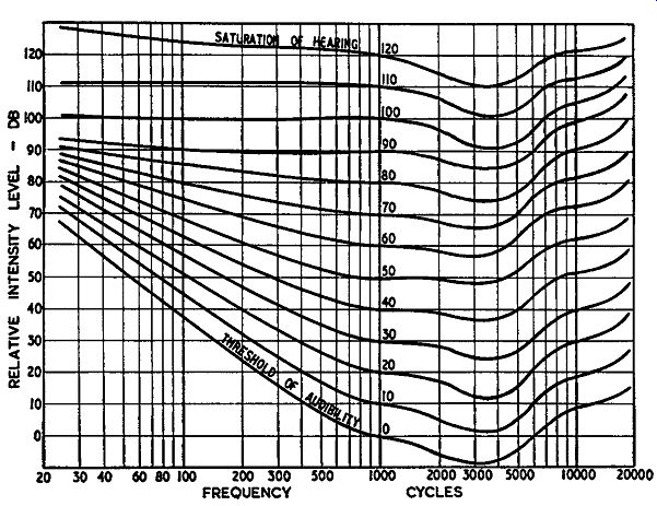
Fig. 901. Loudness sensation contours obtained by Fletcher and Munson.
The shape of these contours forms the basis of the discussion about requirements
for a loudness control.
Some have concluded that a loudness control needs to compensate for the average hearing characteristic of the human ear. This is a fallacy. Original sounds do not sound distorted because we do not wear a loudness control; they seem normal to us the way they are. So if a reproducing chain, from microphone through recording or transmission, playback or reception to the speaker reproduces all the component frequencies at our ears with an intensity identical to the original, it should give the best realism possible from this viewpoint, without loudness compensation.
The unnaturalness of reproduced sound occurs when the intensity of the reproduction is different from the original. Suppose it is 30 db lower. At 1,000 Hz this will reduce the sensation level by three of the curves in Fig. 901 (called a difference of 30 "phons" to avoid confusion with the intensity difference). But down at, say, 50 Hz (assuming the original level was on the "70" curve, representing 70 phons, which has a relative intensity level of about 83 db), reduction by the same intensity, 30 db, to 53 db, brings the sensation just above the 0-phon curve, which means it will only just be audible. So the 1,000-cycle tone will be reproduced at a sensation level a little over half the original (40/70), but the low frequency will almost have disappeared. In fact it will probably be drowned out by the middle frequencies being at such a higher sensation level.
So a loudness control, to correct for this change in level, should turn down the 1,000-cycle level by 30 db, but the 50-cycle level by only 11 or 12 db. This will change the apparent loudness at both points from 70 to 40 phons. Some compensation is also necessary at the high end (but not nearly so much) because the curves are almost parallel above 1,000 Hz. So a change in intensity level will produce an almost identical change in loudness sensation over this range.
Recordings are usually made at an intensity level in the region of 70 phons. If a musician plays a pianissimo passage, he drops the different frequencies by a similar apparent loudness because he judges sound by ear (since he is not reading a volume indicator!). So a quiet passage will automatically be compensated by the way the musician plays it. But a maximum level of 70 phons is high for most living rooms. An auditorium or studio has a reverberation characteristic that helps by "averaging out" the sound intensity so it does not seem unbearably loud as it will in our homes. The same loudness in a living room is too much, except for the enthusiast who thinks high fidelity is synonymous with high intensity.
To get a home listening level the music must be reproduced at about 55 phons (although this varies widely with taste!). Or, to use the music as a background for a get-together with friends, a level of about 40 phons will be plenty. However, turning the volume control down by whatever amount is desired makes the reproduction sound thin, due to deficiency in apparent bass. Thus the loudness control came to be advocated.
In any system there are two conflicting desirable objectives: versatility and simplicity. The protagonists of simplicity state that, if we have a normal tone control for bass and treble boost (as well as rolloff when desired) the loudness control only gives us another control that does the same thing.
It was argued that, since bass boost is the same as treble cut and vice versa (an over-simplification by modern standards!), only one control is needed, which might called a "balance control." It was also stated that separate equalization is unnecessary because tone controls can take care of this function. Advance in the quality of appreciation has proven these arguments fallacious. The educated ear can detect these subtle differences. So any self-respecting system now has an equalization switch or built-in equalization for the most-used characteristic, plus tone controls.
There seem to be two approaches as to whether we need a loudness control and, if so, whether it needs to be additional to the volume control or separate from it.
The first is to use a volume control and adjust the tone controls to suit the loudness at which the program is played. The disadvantage is shown in the curves available in a tone-control system. Very few tone controls will give the shape of frequency-compensation curve required to give correct adjustment for loudness.
If the control has an adjustment for frequency range and degree of boost at both ends of the response (four tone-control knobs), it will be possible (but quite complicated) to obtain correct adjustment for this compensation. With the simpler control that has one knob for bass and one for treble, the requirements for loudness compensation can conflict with those for other tone-control purposes.
The alternative approach uses a loudness control that produces correct compensation for loudness differences as listening level is changed and leaves the tone control to care for other deviations in balance. This approach postulates that, when the reproduced level is the same as the original sound, the loudness control should give level response. To achieve this, we also need a volume (or gain) control to compensate for differences in input level from various program sources-phono, radio or even discs from different companies.
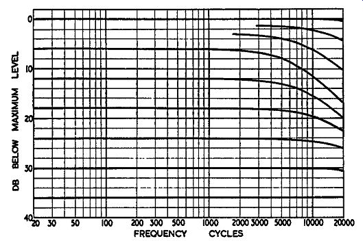
Fig. 902. The effect of a volume control in producing a high frequency
rolloff at some levels. The curves shown represent a 1 meg-ohm control
feeding into a grid input capacitance (total effective) of 100 uuf, or
equivalent combination.
To use this system properly, set the loudness control to a pre determined level, say 50 phons if this is the level at which you normally listen to programs. Then, with the program going into the amplifier, adjust the volume control to your normal listening level. Having set this level, adjust loudness, if desired, by the loudness control. The effect should be just that of changing loudness, without apparent change in quality or balance. This will work quite well and gives pleasant handling, but there is one more question. How do you know when you have the right combination of setting between loudness and volume control? Strictly speaking, you don't. This is a matter of individual judgment, which may be in error. But the method of control is easier to use, even if not ideal. If part of your loudness-control function is served by the bass control or vice versa ( once you have good balance established) the loudness control will give a better loudness adjustment than the other method because loudness differentials are similar over quite a range of loudness levels.
Thus we have two approaches. Of course, a volume control with good tone controls is preferable to a poorly designed loudness control-and some loudness controls do not produce anywhere near the right characteristics. But there is one method that is difficult to justify: a control with a switch that converts it from loudness to volume-control action. If a preamplifier is to be used exclusively with program material in which an input level of 1 mv at 1,000 Hz, for example, always corresponds to a loudness of original program of 70 phons, then no gain control is needed only a loudness control. If you intend only to replay a program at its original loudness, whatever its source, then you do not need a loudness control, only a volume (or gain) control to take care of differences in electrical level at the input that do not represent corresponding loudness differences. But a preamplifier is not likely to be required for one or the other of these requirements. If it is not to be worked under either exclusively--admittedly unlikely then both methods of adjustment should be available simultaneously.
It would seem that the only use for an amplifier with a switched loudness or volume control can be this: First, try the program using the loudness control. If the channel level at the input is correct for the gain of the preamplifier so loudness setting will correspond, you are in luck and can use the control as a loudness control. Otherwise, you must switch back to volume control and rely on the tone controls to compensate for loudness differences.
Such an arrangement would seem little better than no loudness control.
There is an effect that is occasionally confused with the requirement for a loudness control. Sometimes a volume control drastically reduces high and low frequencies when turned down.
The reduction in apparent low frequencies is due to the loudness contour difference effect. But the high-frequency loss is a real electrical loss. It is caused by using too high a value of potentiometer for the volume control, according to the input capacitance of the following stage (Fig. 902). When a volume control is at maximum, the source resistance of the preceding stage is coupled directly to the grid of the following stage. But as the volume control is turned down, some of the control resistance is interposed between the source and the following grid, causing increased rolloff due to its input capacitance.
The magnitude of the effect will depend on the input capacitance, which varies from tube to tube, and with operating conditions. But the effect can be minimized or eliminated by using a lower value of volume control. According to the input capacitance used, 100,000 to 250,000 ohms should be satisfactory. But in no circuit will a I-megohm or higher potentiometer be satisfactory.
Position in circuit
This brief review of loudness control operation will help us see what is required in a preamplifier which uses such a control.
The position of the control corresponding to, say, the 70-phon level, must always result in reproduction at a 70-phon level.
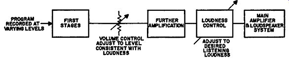
Fig. 903. The general arrangement of loudness and volume control in
an amplifier, showing how to operate the combination properly (see text).
Turning the control down 20 phons means that the reproduction should
likewise always be at the 50-phon level. Only in this way can the loudness
sound right at different settings-or in fact at any setting of the control.
As different recordings are made at varying intensities, even for the same dynamic level in the recording studio, this means some adjustment is necessary to make sure that the reproduction level corresponds to the setting of the loudness control. So the correct operation of loudness and volume control necessitates use of the volume control at some position in the circuit ahead of the loudness control. Fig. 903.
Circuits
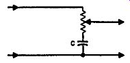
Fig. 904. The simplest modification to a volume control to convert it
into a rudimentary loudness control. The position of the progressive
bass emphasis is determined by the value of C, compared with the potentiometer
resistance.
Fig. 904 shows the simplest circuit that will produce a variable gain or level adjustment and at the same time alter the bass boost. Fig. 905 shows the family of characteristics for various settings of this control. The obvious deficiency is that it does not have an off position. At the bottom end, it has an indefinite 6-db-per-octave rolloff which gives muffled low-level reproduction.
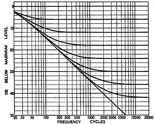
Fig. 905. Family of curves produced by the circuit of Fig. 904 at different
settings. This arrangement does produce the right variation of contour
with level.
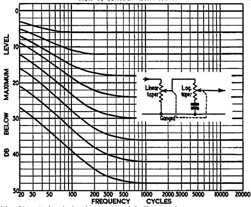
Fig. 906. A simple loudness control built round a two-gang potentiometer,
and the kind of response characteristics this circuit can give.
Fig. 907. A combined control using a tapped potentiometer. Typical values using a 100K potentiometer: R1, 75K; R2, 25K; R3, 3.6K; R4, 47K; C1, .1 uf; C2, .0015 µf. Other values in same proportions would produce similar responses.
Fig. 906 shows one circuit which overcomes this by using a ganged control. The first control, a linear potentiometer, does not have much effect--only 6 db--throughout the upper half of its rotation; most of the gain control in this part of the rotation is due to the second potentiometer, which uses a logarithmic taper. But in the lower part of the rotation the first stage of the control insures that it goes right down to an off position instead of producing a muffled effect.
An alternative method without two separate resistance elements, utilizes a single potentiometer with a fixed tapping. A separate resistor and capacitor are connected to this tapping point to produce the bass-boost effect. This circuit, however, limits consider ably the amount of boost achievable. The boost gets progressively greater as the volume is turned down until the slider reaches the tapping point. From here to the bottom of the control the boost remains constant. While this is an improvement on a control with no such compensation, it is far from adequate control for true loudness effect.
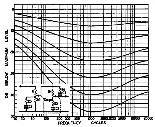
Fig. 908. A two-gang control giving very good loudness compensation.
The curves shown are for rotation over the upper half of the control
movement. The lower half will produce additional attenuation without
much further compensation. Typical values: R1-R2, 75 + 25 == 100K; R3,
3.6K; R4, 500K; R5, 22K; R6, 220K; CJ, .2 µf; C2, .015 µf; C3, 100 µµf.
So far we have not considered any compensation for the treble end of the response. Unless it is necessary to compensate for high frequency losses due to the volume-control effect only a small degree of compensation is needed here. But it does definitely improve the presence effect. A practical circuit combining the two kinds of control is shown in Fig. 907. This uses an additional resistance and capacitor to produce an ultimate of about 10-db lift to correspond with the low-frequency boosting effect.
However, none of these circuits provides adequate boost at the low end. This should get progressively more down to the low frequencies if it is to produce really high-fidelity low-level effects when turned down. To achieve this we really need a two-stage arrangement (Fig. 908). Here the tapped control gives quite a satisfactory additional boost at the extreme-low-frequency end.
The main boost is provided by the untapped potentiometer, padded out with an additional resistor to achieve the correct rate of change in combination with the tapped section. Variable high frequency response is achieved by using a capacitor and resistance to shunt the upper end of the second section.
Continuously variable or stepped
Many other loudness controls have been developed with varying degrees of accuracy and circuit complexity. There is one more question to consider: whether the loudness control needs to be continuous or whether certain fixed settings would be preferable.
Some loudness controls consist of a twenty-position, 2- or 3 pole switch, like those used for professional attenuators, into which separate networks are connected for each position to give an appropriate compensation, corresponding to the Fletcher Munson characteristic. This can produce a loudness control of extreme precision but also one that can be very expensive due to the large number of components.
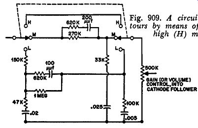
Fig. 909. A circuit for giving three definite contours by means of a
selector switch, identified as high (H) medium (M) and low (L).
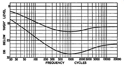
Fig. 910. The contours produced by the circuit of Fig. 909.
There is a good argument for using a switched control, in which compensation is provided only for three or four levels. On the basis of a normal recording level of about 70 phons, the upper position passes the signal through without any compensation whatever as the top position of a good loudness control does. The
middle position inserts about 14- or 15-db attenuation and a corresponding amount of compensation. A lower position inserts approximately 25 to 30 db of attenuation to give low-level re production and provides a corresponding degree of compensation.
This approach is based on the philosophy that most people usually want t9 listen at some specific order of level. Compensation is provided to suit these general orders of level. Finer adjustment can be achieved with the volume control and, if need be, slight adjustment of the tone control. Fig. 909 shows a schematic for this type and Fig. 910 gives typical curves. Choice here is a matter of individual preference rather than of engineering merit.
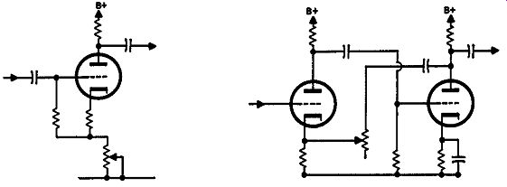
Fig. 911. A single stage feedback circuit that gives a degree of volume
control-but no "off" position.
Fig. 912. Using two stages gives a wider range of control, but involves design problems to maintain linearity.
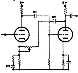
Fig. 913. The two stage arrangement can be modified to give deliberate
loudness contour variation.
Feedback types
A straight (uncompensated) volume control can be achieved by the use of adjustable negative feedback (Fig. 911). Here adjust able feedback in the cathode circuit varies the gain of the tube.
One disadvantage is that it does not provide an off position-only a limited range of gain control. It does have the advantage that negative feedback for the lower levels reduces distortion.
By using the feedback over two stages (Fig. 912) the range of the control can be increased somewhat. However, there is a problem here in producing a uniform flat response, due to the variation in feedback parameters. If these parameters are deliberately controlled (Fig. 913), a convenient form of loudness control is produced. Here the feedback capacitor C2 is responsible for the progressive bass boost as feedback is increased and gain reduced, while the small bypass capacitor C3 produces a progressive high frequency boost up to 6 or 10 db, by choice of suitable components.
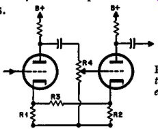
Fig. 914. This circuit uses positive and negative feedback, as explained
in the text, to extend the control range of the potentiometer; in this
case as a straight volume control.
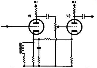
Fig. 915. A modification of the circuit of Fig. 914 to incorporate loudness
compensation functions. In this circuit the "bias for V1 is principally
determined by the resistance in series with the inductor (which may well
be its de resistance). The relationship between the remaining components
determines the degree of compensation, and the frequencies at which it
occurs.
Another feedback volume control (Fig. 914) uses positive and negative feedback. When the control is near its bottom end, R3, coupling the two cathodes, does not contribute any appreciable effect because the signal at the second cathode is considerably smaller than that at the first. However, R1 produces considerable degeneration in the first stage, maybe 6 to 12 db. As the slider is moved up the control to the top end, the signal at the second cathode increases and R3 produces positive feedback or regeneration, cancelling the negative feedback or degeneration in R1, due to the cathode current of the first stage. It may also provide regeneration beyond this cancellation, thus increasing the range of control provided by volume-control resistor R4 by as much as 20 db. The principal advantage is that it enables a wider range of gain control to be used with either a linear or semi-log potentiometer.
The only convenient way to make this circuit into a loudness control is by bypassing R11 with an additional inductor and resistance. By choice of a suitable component these can be incorporated into the one iron-cored coil. The circuit is shown in Fig. 915. The inductor and resistance provide a swing in the bass boost or rolloff in this case, while the capacitor and resistance do the same thing for the high end. With this arrangement the level response will probably be achieved somewhere below the top end of the control.