RECTIFIED ac for the plate supply of amplifier tubes can be obtained from high-vacuum rectifier tubes, from gas tubes (mercury vapor), from metal (selenium or copper oxide) rectifiers or from vibrators (for operation from low-voltage storage batteries such as for car radios). In all cases the rectified ac must be filtered and smoothed so that it is steady dc, otherwise hum, usually the second harmonic of the supply frequency, will be injected into the amplifier. Almost invariably high-vacuum rectifiers are used for domestic equipment, presumably on the score of cheapness, but metal rectifiers have much to commend them.
The operating conditions for rectifier tubes are given in some detail in tube manufacturers' handbooks and there is no point in repeating such information here. This section will be concerned with explaining the various types of rectifier circuits and considerations of filtering and smoothing. It was made clear when discussing output tetrodes in high-fidelity amplifiers that a stabilized plate and/or screen supply was essential for the best results, so methods of obtaining this are described.
Half-wave rectifier
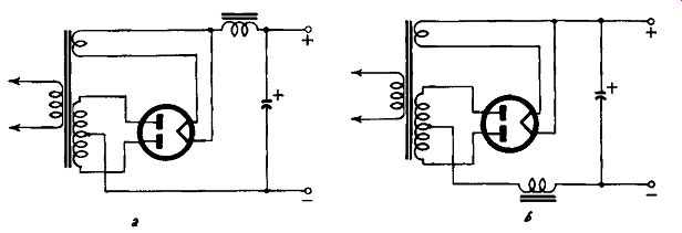
The simplest circuit is the half-wave rectifier, shown in Fig. 901; circuit a shows a thermionic rectifier, ca metal rectifier, both with a capacitive load. The waveform of the output of the rectifier tube is shown at b; that of the metal rectifier with capacitive load at d. With a resistive or inductive load the waveform is the same as that of the tube rectifier.
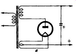
Fig. 901-a. Half-wave thermionic rectifier.
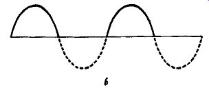
Fig. 901-b. Half-wave rectifier output waveform.
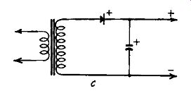
Fig. 901-c. Half-wave supply using metal rectifier.
Since half the sine wave input of the power line is suppressed, there is necessarily an interruption of the supply which must be smoothed out in the filtering system. Imperfect smoothing will result in a hum at the line frequency.
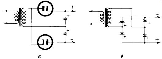
The rectified output can be made continuous (although varying between peak and mean voltage) by using two rectifiers in opposite phase. These are ordinarily combined in one envelope to form the usual full-wave rectifier, as shown in Fig. 902, where, again, circuits for thermionic and metal rectifiers are illustrated, together with the waveforms of the respective rectifiers. Imperfect smoothing, as mentioned earlier, will obviously result in hum at double the supply frequency. The higher the frequency of the ripple to be smoothed, the easier it is to smooth it, so full-wave rectification is preferred to half-wave in audio design.
Bridge rectifier
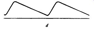
Fig. 901-d. Output waveform of metal rectifier with capacitive load.
All types of rectifiers have a stated maximum power output. If the current taken is reduced, the voltage output can be increased and vice versa. If the required power is beyond the resources of a given rectifier, then it must be duplicated or a larger type chosen. Connection can be made in parallel (as in the similar case of paralleled output tubes) or in bridge fashion.
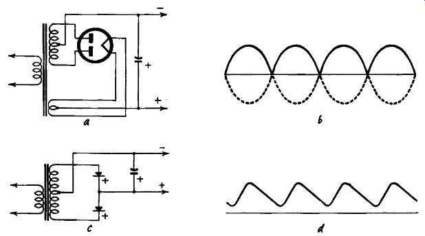
Fig. 902. Full wave rectifiers (a and c) and their output waveforms
(band d).
Bridge connections are shown in Fig. 903 for both thermionic and metal rectifiers. From an examination of Fig. 903 observe that four half-wave rectifier tubes must be used, the required connections being impossible with two full-wave units. Further more, three separate filament or heater windings must be provided in the power transformer. As this increases the cost of the trans former considerably, it is customary to use two full-wave rectifiers in parallel when one filament winding is all that is needed. With metal rectifiers bridge connection is widely used and very convenient, for the circuit arrangements of Fig. 904 can be arranged in a single stack of elements. The waveforms of the output of a bridge rectifier are identical with those of Fig. 902.
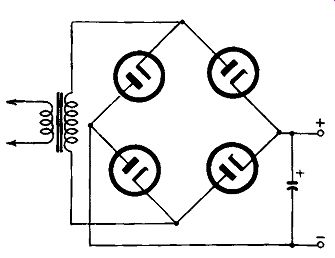
Fig. 903. Thermionic bridge rectifier.
Voltage doubler
The voltage-doubling arrangement is very convenient for high values of rectified volts because the transformer secondary need have only half the turns required for a half-wave, full-wave or bridge rectifier; but since the input volt-amperes to the rectifier must be the same, the current is double. Voltage-tripling or -quadrupling circuits are also available. Voltage-doubling circuits are shown in Fig. 905. Since the reservoir capacitors are in series their working voltage need be no greater than that required for ordinary rectifiers.
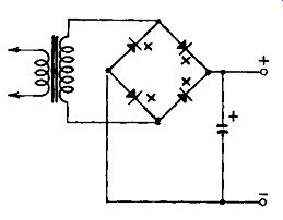
Fig. 904. Metal rectifier bridge connection.
Filters
Rectifiers work into a filter whose function is to smooth out the ripple on the rectified output voltage. The part of the filter directly connected to the rectifier can be either a capacitor or an inductor, these alternative methods being termed capacitor input or choke input respectively. The circuits of Figs. 901 to 905 show capacitor input arrangements with no further filtering. The choke input equivalent of Fig. 902 is given in Figs. 906-a, -b, where the choke can be connected in either the positive or negative leg.
Capacitor input filter
For capacitor input, the output voltage of the rectifier is a function of the capacitance of the input or "reservoir" capacitor. The actual voltage will, of course, also be governed by the current taken from the rectifier but, for a given current and power transformer secondary volts, the rectified volts will increase as the capacitance of the reservoir capacitor is increased. If this is increased too much the rectifier will be seriously overloaded during parts of the supply cycle.
Figs. 905-a,-b. Voltage-doubler circuits: a) using thermionic rectifiers;
b) using metal rectifiers.
With capacitor input, the ac volts applied to the rectifier, thermionic or metal, need never be greater and are usually slightly less than the de volts required. With a full-wave rectifier of the type shown in Fig. 902 the required voltage must be applied to each plate so the voltage across the center-tapped transformer secondary will be double that required for a half-wave or bridge rectifier and four times that needed in voltage doubler. But as the total volt-amperes is the same in all cases, the current will be proportionately reduced. The design of the transformer cannot, however, be undertaken without a knowledge of the value of the reservoir capacitor. The necessary information can be obtained from the data books of tube manufacturers, and, if data for metal rectifiers is not obtainable, it can be taken as similar to that for thermionic rectifiers.
Choke input filter
With choke input, the ac voltage to be applied to the rectifier is appreciably higher than the de voltage required. This seeming disadvantage is outweighed by the good voltage regulation of the choke-input system. This inductor has a minimum critical value according to the current demand (usually given for maximum rating in the tube manufacturers' data books) but beyond this, increase of the choke inductance produces less ripple in the rectified current; a choke of infinite inductance would produce ripple free current. The inductance of the choke is dependent on the amount of direct current passing through it and variation of inductance through fluctuations of current is restricted by using .a choke having a gap in the core. So-called "constant-inductance" chokes must necessarily have appreciable gaps, but a smaller gap
Figs. 906-a,-b. Choke-input filters: a) choke in the positive leg; b)
choke in the negative leg.
than would normally be necessary can also be used. The critical value of inductance required decreases as the load current rises, so the characteristics of a choke using a smaller-than-normal gap (one having an appreciable change of inductance with change of current) can be utilized. Such a component is usually called a swinging choke. It can be used only immediately after the rectifier; further chokes in the filtering and smoothing system should have nearer to "contant-inductance" characteristics to insure adequate smoothing for the varying currents resulting from the behavior of the output stage of the amplifier.
In class-AB2 and class-B amplifiers the conditions of minimum current are such that an unduly high value of inductance would be required, in which case it is customary to add a bleeder resistance to the load to keep the current at a figure large enough to enable a reasonable sized inductor to be used. Even with class-AB1 amplifiers using tetrodes, a bleeder potentiometer may be desirable for the screen supply, not only to permit a lighter rating of swinging choke inductance to be used, but to insure reasonable stability of the screen voltage, the variations in screen current then being negligible as compared with the steady current drawn by the bleeder.
Two-stage filter
The ripple-removing filter is generally of the inductance-capacitance type since heavy current through a resistor would cause a serious voltage drop. Except for the cheapest equipment, this...
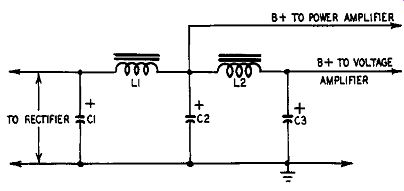
Fig. 907. Two-stage capacitor-input filter.
…would be two-stage (see Fig. 907). The first capacitor C1 must be rated to withstand the peak voltage of the rectifier and to avoid possible breakdown should be generous, with a test voltage three times the de working volts. C2 has only small ripple on it and so ...
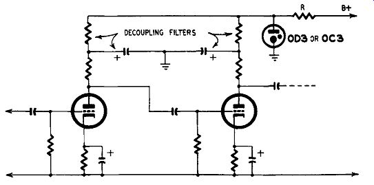
Fig. 908. Decoupling network using a V-R tube in place of capacitive
bypassing.
... the test voltage need be only double the de working volts (i.e. smoothed plate-supply voltage). If only for economy's sake, to avoid having two chokes of generous design to carry the whole plate current of the amplifier, the output stage could be fed from the first stage of the filter. It may even be desirable that it should be done this way, for it will be obvious that the impedance of the circuit C1-L1-C2 is common to all plate circuits; if all plate sup plies are drawn from the second stage the impedance of the section L2-C3 is added to the common impedance. This may give rise to low-frequency instability in the amplifier, usually prevented by decoupling circuits, so it is desirable to reduce the common impedance as much as possible. As two filter stages are essential for high-gain amplifiers, the best way out is to take the output plate supply from the first section of the filter. Yet hum must be avoided and adequate inductance and capacitance are necessary. Note that there are two resonant circuits in Fig. 907, C1-L1-C2 and C2 L2-C3. These must resonate at a frequency well below the supply frequency to avoid any undesirable resonance effects. Minimum values of inductance are:
For frequency ( hz) 25 50 60 100 120
L1 or L2 = 56 14 7 3.5 1.8
C1 + C2
X or
C1 X C2
where C is in µ.f and L is in henries.
C2 + C3
C2 X C3
These figures should be exceeded as far as the economics of the design will allow. The inductance obviously is taken at the full current passing through the chokes. As the current through L2 is generally quite low, it is quite feasible to have the inductance high, even as much as 100 henries. It is rarely desirable to have the inductance of L1 less than 15 to 20 henries if the equipment is capable of reproducing very low frequencies. With a single smoothing stage for the output tubes, C2 can very well be as great as 24 or 32 µ.f. C3 need rarely be more than 8 µf.
However, the audio designer must also consider various other factors such as physical size, price, availability, etc. In preamplifier stages taking low plate current, a third filter stage of the resistance-capacitance type can very well be added as additional smoothing for a sensitive part of the amplifier.
Decoupling filters
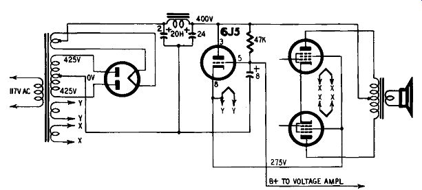
Fig. 909. Simple form of stabilized supply using a triode.
From what has already been said, this R-C filter may introduce instability through common impedance in the plate-supply circuit.
Also, if the whole amplifier has considerable gain, there may still be insufficient smoothing to eliminate all hum. The amplifier circuits so far shown have not included decoupling filters, simply on the score of simplicity of illustration. Fig. 908 shows the first two stages of a multistage amplifier with the decoupling filters included in the plates of the tubes. Resistor R in the plate-supply line can be considered as the filter resistor for the third filter section. Normally the tube end of this resistor would have a capacitor connected to ground as the low-impedance ac shunt. If instead of the capacitor a gas tube, such as the 0D3 or 0C3 is used, considerable benefits are secured. The tube acts as a voltage regulator since gas tubes have the property of maintaining a constant output voltage by varying their internal resistance as the input volts vary; it is therefore an almost perfect shunt to ground for ac, which in itself is a varying voltage. So although the gas tube is primarily a voltage regulator, it has the further merit of acting as a complete hum eliminator and a contributor to stability be cause of its very low impedance.
As mentioned in the section dealing with tetrode output stages, distortion is avoided if the plate and screen voltages can be stabilized. Actually the screen voltage is much more critical than the plate voltage, and a stabilized voltage supply can be obtained by using one (or two in series for voltages beyond the control capabilities of one) gas tube shunted across the supply lines. More refined control can be obtained by using triodes or pentodes in conjunction with gas tubes. It must be said, however, that the writer considers many of the stabilizing circuits somewhat complicated and puts forward a very simple circuit which he has used with great success for many years (see Fig. 909). This involves only a 6J5 tube and a few small components as extras but works extremely well. And if even this simple arrangement appears too much trouble, it can be taken as axiomatic that no high-fidelity amplifier can give its best unless at least part of the supply from the power unit is properly stabilized. Tubes must work under their optimum conditions, and, if voltages are all over the place as a result of the applied signal causing changes in current through the smoothing filters, precise performance is impossible.
Iron-cored inductor characteristics
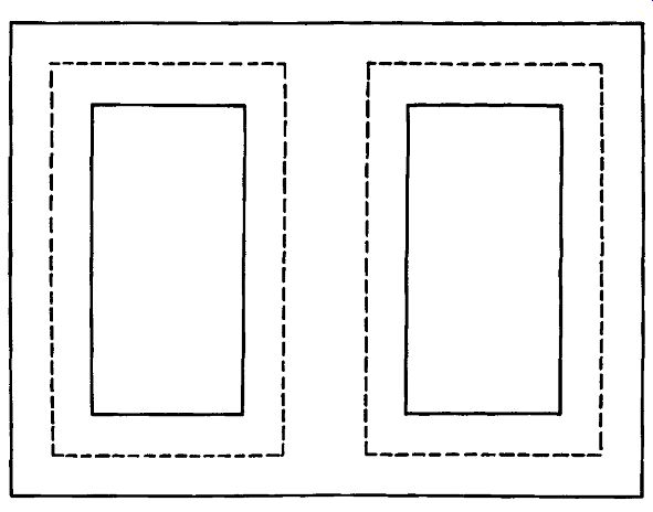
Fig. 910. Typical transformer or choke construction. The mean magnetic
path is shown by the dashed lines.
There is no technical difficulty in designing a choke, output transformer or power transformer to any given performance, but since the manufacture of these calls for skill and experience it is customary for the audio designer to acquire these components from specialist manufacturers. The designer should, however, have some knowledge of the properties and characteristics of these components to ensure a sound choice being made.
The inductance L of an iron-cored coil is given by the formula
L = 3.2 (n)2µa hy
…where n is the number of turns; ,-,, is the permeability of the core to ac; a is the effective cross-section of the coil in square inches and l is the length of the magnetic circuit in inches (shown as a dashed line in Fig. 910).
The permeability depends on the core material used, which, except for specially prepared molded cores, consists of a stack of iron alloy laminations, insulated on one side to reduce losses.
Laminations come in pairs, either as E's and I's or T's and U's.
The center section of the core should be twice the width of the ...
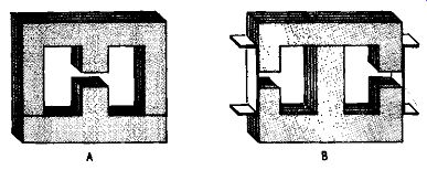
Fig. 911. Several possible arrangements of laminated-iron cores.
... two side limbs, a seemingly obvious requirement. Some laminations are produced which are badly designed in this respect.
If the choke (or of transformer, which is simply a choke with a secondary winding) carries no de the laminations are inter leaved, making for easier handling, and a push-pull output trans former can have the same arrangement and work satisfactorily if the output tubes are balanced for plate current.
It will be obvious that the size of the core has a bearing on the value of inductance produced by a given number of turns but an even greater effect on the size of wire required to get the same turns into the winding window available. A small core postulates a finer gauge of wire with a substantial increase in de resistance.
When a choke has to carry dc, the voltage drop due to a high resistance winding may not be acceptable. For ac considerations, the core must not be too small if substantial power is handled.
This is similar to the case of an output transformer which, apart from any de present, has to transform the ac power generated by the output stage. See Fig. 911.
For output as well as power transformers, the optimum core cross-section area in square inches A is given by:
A = V output in volt-amps 5.6
When de passes through a choke, or af transformer, the ac permeability falls. This could be overcome by increasing the size of the core, but the simplest way of increasing the inductance is to provide a gap in the core. This is achieved by placing a layer of insulating material between the two bunched pairs of the magnetic circuit. The determination of the optimum gap dimensions depends on the amount of dc passing through the winding; for currents up to about 2.5 ma in windings of about 1,000 turns little is gained by having a gapped core, but heavier currents demand it. Typical usage of gapped chokes is in the smoothing chokes of power supply units.