The problem of estimating the future performance of tubes is faced by almost everyone who works with them.
The engineer wants some assurance that he is choosing the right type to do the best job in some equipment he is designing. The maintenance engineer wants to know how long the tubes in his equipment will continue to function.
The service technician wants to convince his TV customers that certain tubes should be replaced before they fail, and the do-it-yourself individual wants to know if any of the tubes he has removed from his set are any good, and if so, which ones. The next two sections will deal with this rather universal problem and will explore some of the methods available for resolving it.
Tubes may be classified according to their various structural differences. When this is done, they will in advertently be roughly classified in accordance with their over-all reliability. In other words, some fairly depend able rules of thumb exist, based on experience alone, which can serve as a first approximation for estimating the service to be expected from certain classifications of tubes. Other modifying factors that may affect specific applications are discussed in succeeding paragraphs.
LIFE EXPECTANCY BY STRUCTURE
Generally speaking, if two tubes are designed to perform similar functions, the one having the larger envelope will prove to be the more reliable. All other things being equal, there appears to be a direct relationship between bulb size and the average life expectancy of tubes. This undoubtedly stems from the simple fact that the larger bulb runs cooler because its larger area permits greater dissipation of the heat generated within the tube. A striking example of this is the 6AQ5 and the 6V6GT, the former being a miniature version of the latter, but carrying the same ratings. The 6AQ5 has never been able to perform at these ratings and still turn in the same life figures as its larger forerunner.
Similarly, there appears to be a fairly good correlation between reliability and the size of the tube elements.
Tubes having larger plate structures and larger grids and cathodes are more reliable than miniaturized versions having the same general characteristics.
It naturally follows that tubes having the greatest spacing between elements are less prone to premature failures than those in which the spacings between elements are much less. This has to do particularly with grid-to-cathode spacings, and is not only due to the reduced insulation paths, but also to the fact that the nearer the grid is to the cathode, the hotter it will run and the more likely it is to become contaminated with the coating material on the cathode.
The length of the mount, or more precisely, the length to-height ratio seems to be important also. Here, the evidence seems to support the short, stubby structure over the long, thin structure. There are several reasons, but they all add up to the simple fact that the shorter mount is usually more rigid and permits less bending between the upper and lower mica supports.
Generally, it is also true that the more complex the tube becomes in terms of the total number of active elements, the more prone it is to a premature failure. Thus, the simplest tubes, which are the diodes, are generally the most reliable ones. This is, of course, modified by their usage as will be pointed out shortly. Next come the tri odes, followed by the pentodes, and finally the pentagrid converters. Actual field returns support these failure ratios, although the exact reason for them is not as clearly documented. It can be assumed that the laws of statistics certainly play some role in this situation. The probability of a short occurring, for example, must inevitably increase if the number of opportunities increases-and the more elements there are within a given structure, the more chances there are for a short to develop.
The same rule of thumb exists for multisection tubes, but not for exactly the same reasons. In a multisection tube, we usually have two or more completely separate, individual tubes. Yet, they are looked upon as a single tube. The chances of a failure occurring within a given envelope increases at some rate which is not simply the arithmetic sum of the number of units within the envelope. It is more nearly an exponential rate, largely due to the fact that if one section fails, the other section must inevitably be called a failure also, since they are inseparable. There is also the matter of interaction between the elements. One section may be operated so that it contributes to the failure of another section while suffering no serious malfunction itself. This is especially true of the nonsymmetrical multisection tubes.
A nonsymmetrical multisection tube is one in which the sections are not identical--for example, a triode and pentode within the same envelope. Due to differences in us age, one section will more than likely operate at a higher dissipation level than the other. When this is true, the normal processes of degradation which take place during life, such as gas evolution and metal evaporation, will not occur at uniform rates for each section. It is a natural phenomenon that these processes of degradation will affect the cooler section first. The lightly-loaded section usually suffers for the more heavily-loaded section. Failure occurs prematurely since neither would have failed for this reason had they been operated individually.
Although metal tubes are not much of a factor today, it is interesting to note that they have been, at least twice in the past, and that they are making a new bid for acceptance in a new, miniaturized form today. Historically, the metal receiving tubes of the '30's and the metal TV picture tubes of the '50's did not prove as reliable as their all-glass equivalents. Whether or not the latest attempts in the direction of metal-enclosed subminiatures will prove to be an exception to this rule remains to be seen.
LIFE EXPECTANCY BY APPLICATION
Just as there is a general relationship between tube structures and their life expectancy, so is there a fairly close relationship between tube applications and life expectancy. Naturally, there are many ways a tube may be used in a given service. Its actual life will depend upon whether the specific application is conservative or excessive for that class of service.
Nevertheless, certain types of service are known to enjoy better average life expectancies than others (Fig. 7-1). By recognizing that some forms of service are inherently more severe than others, and that a higher failure rate is to be expected from tubes in these services, a lot of imaginary problems can be ruled out before they get started. If the user knows that his 400-horsepower rolling palace is supposed to burn more gas than his neighbor's two-cycle scooter bike, there are apt to be less hard feelings than if he doesn't know it! Tube applications can be classified in several ways, but there are three main areas that affect their life most intimately. Of greatest importance are the three inseparable ones-voltage, current, and temperature. Tubes operated at low voltage and current densities will probably also run fairly cool. These are the tubes that seem to live forever. Conversely, tubes that operate at the other extreme will not live very long. Naturally, there are combi nations of conditions between these extremes, but the presence of any one of these three factors will inevitably shorten the life of any tube.
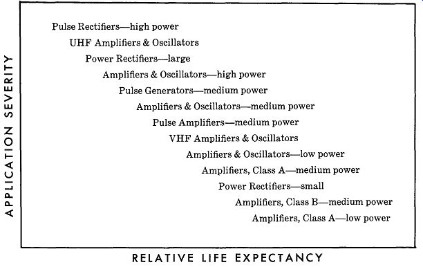
---------Fig. 7-1
Pulse Rectifiers-high power UHF Amplifiers & Oscillators Power Rectifiers-large Amplifiers & Oscillators-high power Pulse Generators-medium power Amplifiers & Oscillators-medium power Pulse Amplifiers-medium power VHF Amplifiers & Oscillators Amplifiers & Oscillators-low power Amplifiers, Class A-medium power
Power Rectifiers-small Amplifiers, Class B-medium power Amplifiers, Class A-low power
RELATIVE LIFE EXPECTANCY
---------------------
There is then the question of intermittent versus steady state operation. Once again, there are exceptions, but in general, tubes that are operated continuously, without interruption, are more inclined to give long, trouble-free service than those that are operated intermittently. This is because many of the reasons for sudden failure are the result of strains developed from heating and cooling.
A hot tube tends to clean up its own gas evolvement.
Most circuit-induced failures usually occur immediately after equipment is turned on after long periods of idleness. By not turning it off, these failures are avoided.
There is a special form of intermittent operation which is not always recognized for what it is and thus deserves some additional clarification. This is the type of service usually referred to as "pulse service." Multivibrators, blocking oscillators, or any tubes which amplify or pass signals developed by these devices are typical pulse circuits. One important characteristic of a pulse circuit is its duty cycle. This is the percentage of time it conducts compared to the total time the equipment is turned on.
Typical TV pulse tubes have duty cycles of less than 15 percent. This means that the tube is conducting for only 15 percent of the time and is cut off 85 percent of the time.
This is intermittent operation even though the tube never cools down between cycles. Tubes used in this manner, and not specifically designed for this type of service, will be affected by the formation of cathode interface resistance, which will lead to an earlier-than-normal loss of transconductance. Tubes intended for pulse operation are made and processed differently from those intended for DC or Class-A operation. When designed properly, they do not develop interface resistance.
A third general classification for the application of tubes may be made according to the frequency at which they operate. There is a fairly close parallel between frequency of operation and useful life. This is due, in part, to the fact that most tubes intended for use at very high frequencies are constructed differently from those in tended for use at lower frequencies. Thus, most high frequency tubes tend to be small, and to have very closely spaced elements. This is an inevitable compromise on the electronic laws that govern transit time, lead lengths, interelectrode capacities, etc. Nevertheless, tubes operated at high frequencies, even those not especially de signed with that purpose, do suffer from certain effects not so noticeable at the lower frequencies-and these effects do foreshorten tube life.
The normal amounts of gassing and insulation leakage which all tubes suffer from as time elapses have a more detrimental effect on their performance at higher frequencies than they do at some lower frequency. Thus, a tube may stop oscillating at 750 megacycles, yet be quite satisfactory as an oscillator at 300 megacycles. A given amount of gas current may have no ill effect upon a tube at 5 megacycles, yet may raise its noise output by enough to be quite unusable as an amplifier at 50 megacycles.
In the case of power tubes which are operated at the higher frequencies, a sort of compounding of these effects takes place. Because the internal losses are higher, these tubes tend to develop more heat as their frequency of operation is increased. This increased dissipation contributes to a more rapid evolution of gas and to the earlier formation of excessive leakage paths. Normally, tubes intended for operation as power amplifiers or oscillators at the higher frequencies are derated as frequency increases. This is an attempt to compensate for these natural effects. While this derating does result in their enjoying more nearly comparable life spans to tubes operated at some lower frequency, they are generally not the same.
Where several tubes of the same type are used in the same piece of apparatus, it is often possible to use those that are no longer satisfactory in the highest frequency stages in some other lower frequency stage. Many hours of additional satisfactory service may thus be obtained from them.
TESTS FOR INITIAL PERFORMANCE
One of the most common preoccupations of those who use tubes is the practice of pretesting tubes before using them in an endeavor to determine their ability to perform satisfactorily. There are many ways of pretesting tubes, but very few of those in common usage are worth the time spent in performing them. Unless conducted properly, most tube testing is about as ineffective in predicting any thing as reading tea leaves would be. Even when con ducted according to the best techniques known to those who have spent a major part of their lives studying tubes, the results are often disappointingly vague. Some tests correlate better than others. Some applications require a measurement of so many characteristics that correlation becomes almost impossible. One thing will become apparent, however, as we examine some of the specific tests which can be performed: there is no one test that gives very good correlation with any application. Even the simplest application usually requires that several readings be taken before an estimate of the tube's ability to perform satisfactorily can be made.
Let there be no mistake about one thing. Instruments are available for measuring every known characteristic of tubes, no matter how obscure or involved it may be.
These instruments (Fig. 7-2) are very complex and highly accurate in their specialized area of measurement. This is not the difficulty when it comes to predicting tube performance on the basis of measurement. The trouble lies in trying to relate the many measurements that can be made, and from them to preparing an accurate prediction of tube performance in a given piece of apparatus. No ma chine capable of performing this complex function exists; consequently, no exact method for measuring and predicting tube performance exists either. What is done is a compromise; imperfect as it may be, it serves the useful purpose of controlling uniformity and estimating actual performance to a reasonable degree-as long as the statistical approach is applied to many tubes and not to just one tube.
Testing for Gain
Perhaps the simplest test to correlate with actual performance is the one commonly associated with Class A amplifier gain. Assuming the frequency to be below 10 megacycles, transconductance gives a very good estimate of circuit gain or amplification, provided the test conditions are the same as those in the circuit. For example, if the tube is an IF amplifier operated with 100 volts on the screen, 250 volts on the plate, and -1 volt between grid and cathode, and these conditions are set up in the classic transconductance circuit, the reading will bear a close correlation to actual performance. It should be re membered that this is only a relative reading and is meaningful only when compared to several other readings taken on similar tubes under the same test conditions.
The tube having the highest transconductance should have the highest measured gain in the IF strip, provided all tubes have the same plate resistance. If they do not, the tube having the highest combined transconductance and the highest plate resistance will have the highest gain.
Power Output
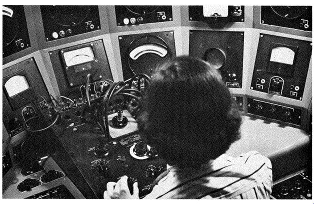
Fig. 7-2. Master tube bridge for measuring every known characteristic of tubes.
( Courtesy of CBS Electronics.)
There is no power-output test that correlates well with performance, except to operate the tube in a manner more or less identical to circuit conditions and to measure the true power output across the proper load. This can be done at one frequency, for example, 60 cycles; as far as the tube is concerned, it will prove to be quite accurate even at relatively high frequencies-say up to 60 megacycles. The load must be appropriate for the chosen test frequency, and the same current and voltage conditions that exist in the actual circuit must be used during the test. It is important that the drive voltage and, in some cases, the drive impedance also be the same. When these conditions are met, the correlation will be very close to 100 percent. At frequencies higher than 10 megacycles, RF loading effects, lead inductances, and interelectrode capacitances become important. Therefore, correlation will become progressively poorer as the frequency is raised.
AC Amplification
Voltage amplifiers or tubes having very high Mu are best tested in a circuit which simulates their AC and DC conditions, with the result being read as a simple ratio of voltage in versus voltage out. Mu can, of course, be read on a tube bridge, but this characteristic alone does not take into account many of the practical circuit conditions encountered and, therefore, correlates poorly. In measuring AC amplification, it is extremely important that the tube be tested with the same high-impedance grid resistor normally found in the circuit, and that the grid drive voltage remain safely below the effective grid bias level. This usually means a signal of 0.5 volt or less, in order to prevent grid clipping which produces a false reading. The output should be read as a simple AC voltage, using a high-impedance meter in the plate circuit.
It is important that the signal source have a relatively high impedance so that it simulates the normal stage preceding a voltage amplifier stage. It is interesting to note that when properly conducted, this is a very sensitive gas test, also, because even a very minute amount of gas will cause a nonsymmetrical loading of the input signal, thereby reducing its amplitude and consequently reducing the output signal. This same amount of gas will be un detected in so-called "gas" tests, but it will cause serious distortion during actual application of the tube.
Frequency Converters
Correlation is most difficult for converter tubes, especially those of the multigrid type. These are really pentodes with a triode built within the usual grid-to-cathode spacing. There are several characteristics you can measure, but when you put them all together, the results often don't agree with the actual performance measurements.
To begin with, you can ignore the pentode and measure the triode, which is usually measured for transconductance. Then you can separately measure the pentode for transconductance. It just so happens that there is a fair measure of correlation between these two measurements over a limited range of oscillator coil characteristics, and it usually goes in the inverse direction for the triode and directly for the pentode. The reasons are as follows : Since the triode is usually used as a self-excited oscillator, it is self-biased by means of its grid resistor. This bias also sets the operating point for the pentode since the oscillator grid is the number one grid, or the one nearest the cathode. Since the transconductance of the triode will determine the amount of feedback obtained from a given oscillator coil, and since this will control the amount of drive delivered to the number one grid, the higher the transconductance of the triode, the higher will its bias become and therefore the further will the pentode be biased toward cutoff. So, the pentode's effective trans conductance will be decreased by the high activity of the oscillator. But since the oscillator is self-biased and, there fore, more or less self-regulating, this relationship is valid only over a very narrow design range for the oscillator coil. Outside this range, the relationship may reverse.
Some mixer circuits use an additional characteristic of the pentagrid converter tube and thereby render correlation and measurement almost impossible. These circuits introduce regeneration, usually at the IF frequency, either by feeding back some plate circuit energy into the cathode circuit, or by using the screen grid as a partially active element and introducing the in-phase signal by means of a small tap on the IF coil primary. When this latter circuit is used, the transconductances of the screen grid, control grid, and triode grid all become interrelated in a complex manner. The result is that no reasonable correlation will exist between any of these measurements.
There are methods for testing pentagrid converters, using 60 cycles to drive both the number one and number three grids at the proper amplitude and in the proper phase, and then measuring the degree of cancellation in the output. This method, while useful for control purposes, is not very effective in correlating with actual application. About the only successful method of measuring pentagrid converters is in a circuit which duplicates the actual application, at least, insofar as the oscillator coil and grid resistor are concerned. The signal is introduced into the control grid circuit and the converted IF frequency is measured in the plate circuit. The relative magnitude of the two signals is expressed, in micromhos, as conversion transconductance. When the circuit elements are the same as those used in the actual equipment, the correlation is very nearly 100 percent.
Oscillators
Test measurements of oscillators are very often complicated by the fact that they are intended for use at high frequencies. Where an oscillator is to be used at low frequencies, two characteristics are important. Transconductance will determine whether the tube has enough gain to overcome circuit losses and hence sustain oscillations. If some sort of power output is important, then pulse emission may have to be measured. Pulse emission is not to be confused with ordinary DC emission, which is simply the short circuit DC current drawn from the cathode with all other elements connected together as a diode. It is usually conducted at less than 50 volts and was originally intended as a manufacturing process control.
Pulse-emission testing is performed with the individual tube elements properly isolated and connected to appropriate voltage sources. The tube is held in a cutoff condition by a large negative grid bias and is then driven into conduction for brief intervals by a grid driving signal.
If the tube is one where the grid normally swings positive, it will be driven momentarily into this positive grid region by the driving signal. The peak current drawn from the cathode may be very high under these conditions, but will not result in damage if the duration is kept very short.
Thus, the average, or RMS value may be only milliamperes, even though the peak value is amperes.
This method of testing permits a very complete analysis of cathode capabilities, although to be most easily interpreted, it should be read on a scope. A lack of peak emission capability is often the cause of poor oscillator or Class-C amplifier performance, especially as the frequency of operation is increased. Even though the cathode may show excellent DC emission, it may be incapable of sup plying current in sudden, short bursts as is required in oscillators or pulse tubes. This method of pulse-emission testing is essential in evaluating pulse oscillators or amplifiers also.
Another characteristic important to pulse oscillators, generally associated with timing circuits, is what is known as grid perveance. The diode slope of the grid-to cathode characteristic when the grid is positive is an important indicator of significant differences in tubes which, while normal in most other respects, tend to oscillate at the wrong, or at least at a different, frequency.
This characteristic will be measured in the positive grid region and at values of voltage usually less than three volts. By measuring the current to the grid when a + 1 volt is applied to it, the difference between those tubes which operate on frequency and those that do not can usually be distinguished.
Another important characteristic that needs to be measured when evaluating pulse tubes is cutoff. The negative voltage required to reduce the plate current to 50 micro-amperes or less, when the rated plate and screen voltages are applied, is usually what is defined as cutoff. Pulse tubes are supposed to operate very much like a switch.
They have two essential modes of operation, one of which is closed circuit, or on, and the other is open circuit, or off. It is essential that this cutoff characteristic be read with the full potentials applied to the plate and screen electrodes. Many tubes which cut off normally at low an ode voltages, do not cut off well at their operating potentials. When this happens, the "switch" is leaky, and circuits such as horizontal-sweep amplifiers in TV will not function properly. This is a frequent cause for the loss of high voltage, even though there is a reasonable amount of sweep. Failure to cut off properly will have little effect upon the conduction time, and cannot be evaluated by any test which measures the tube in a conducting condition.
Diodes and Rectifiers
Detector diodes have at least two important characteristics, one of which is the diode perveance already mentioned in connection with the grid of pulse tubes. Diode perveance is simply the slope of the rectification curve.
The most significant part of this curve is in the 0-to-3 volt region. The second characteristic is closely associated with the first, but must be separately measured. It is known as initial velocity voltage, or contact potential.
This is the voltage which will be read across a large value of resistance ( one megohm or greater) when connected between the diode plate and its cathode. It should be read on a high impedance voltmeter.
Initial velocity voltage is a negative potential, so it opposes any positive potential applied to the diode plate.
It has a great effect upon the diode curve in the low voltage region. Initial velocity voltage is sometimes used as the bias for several other tubes and, therefore, its actual value may have an indirect effect on the over-all performance of a given piece of equipment.
High-power diodes, such as damper diodes, are some times used to rectify large pulse currents. In such applications, the principal characteristic to be evaluated is pulse emission. Again it should be emphasized that there is no correlation between DC emission and pulse emission.
Defective damper tubes which cause compression on the left side of the picture often will be found to have normal DC emission but a much reduced pulse emission. These same tubes are quite prone to arcing, especially when initial power is applied.
Power rectifiers would seem like very simple tubes to test; compared to some other types, they are. For all practical purposes, they can be tested under load and the voltage output taken as a figure of merit. While this gives assurance that the tube can rectify and that the tube voltage drop has not risen to a serious level, it does not take into account a rectifier tube's weakest link so to speak. Rectifiers must withstand rather high inverse voltages during the nonconducting half of each cycle. During these periods, great damage can occur to the tube and its associated equipment if a certain condition is present. This condition is back emission from the plate. Back emission may be present initially as a result of ineffective process control, or it may develop with use or age. In either event, tubes with high back emission are not good risks. They may arc at any time, or they may rapidly lose peak emission capabilities. Back emission is read as a current flowing away from the plate when it is highly negative with respect to the cathode.
PREDICTING LIFE
The question is often asked, "Is there any method for predicting the life of a tube based on initial readings?" The answer is almost a flat "No." True, there are some characteristics, such as an excessive gas, which some will interpret as a sure sign of early failure. This, however, is not always true. It depends upon what gas is present.
Some forms of gas are normal; others clear up during use; still others cause cathode poisoning. To say that the presence of gas will provide any indication of life expectancy is pretty unrealistic.
Such things as back emission and grid emission are sometimes pointed out as sure signs of early failure, but again, this is not always true either. Back emission, if caused by initial processing, often clears up by itself, and there is at least one very popular transmitting tube that won't function properly unless it has a certain amount of grid emission right from the start! Without grid emission, tubes of this type can't pass the military or the customer's acceptance specifications! There is no single measurement of an initial nature which is of any real value in predicting life. The next section deals with various techniques the trained observer can use to isolate those tubes which have degenerated and are no longer a good risk from a life expectancy point of view. These are not initial tests, and they are not "one shot" procedures, but they are rather effective if properly conducted.