In the preceding sections, we have discussed tubes in a broad, general manner, dealing with those aspects which are common to the vast majority of those in use. In this section, we will take up some of the special-purpose tubes that require individual treatment because of certain un usual characteristics which they possess.
FILAMENTARY TUBES
Filamentary tubes require certain special considerations if they are to provide the maximum useful life of which they are capable. One of the most important of these concerns the way they are mounted. Filaments are generally hung or mounted, in suspension, between some mechanical point on the top mica and the stiff wires in the base. They depend upon tension to keep them taut.
When heated, the filament naturally stretches and, as a result, may sag against some other electrode within the tube.
Most filamentary tubes have a specified mounting position which is usually base down. This provides maximum assurance that filament sagging will not cause a short.
Certain rectifier tubes may be horizontally mounted if the planes of the filaments and the major axis of the plates are so oriented that they lie vertically. There is a standard relationship between the plane of the tube elements and the base so that mounting specifications may read as, for example, in the case of the 5U4G, "horizontal operation is permissible if pins 1 and 4 are in a vertical plane." Due to differences in manufacturing techniques, the actual position of the mount with reference to the base pins may vary considerably among manufacturers. The tolerance on this specification is quite broad and in some cases, it will be found that the tubes are mounted in such a position that their filaments can sag against the plates, causing pre mature arcing and early failures. Where large numbers of tubes are involved, it may pay the user to orient the sockets so that they coincide with the construction of some one manufacturer's tubes and then to insist on using only that brand, or tubes which are physically identical to them, in that equipment. A real improvement in life will result if this precaution is taken.
Another consideration when using filamentary tubes is the matter of their rapid warm-up time. This can be either an advantage or a disadvantage, depending upon the circumstances. In many applications, such as mobile operations, filamentary tubes permit complete shutdown during standby. This gives them a substantial advantage in power economy and increases their useful life since they can be ready for instant operation without the needless burning of filaments that are not actually in use.
This same feature may give rise to undesirable effects when filamentary tubes are used in conjunction with indirectly-heated tubes. These latter types have a much longer warm-up time; therefore, some circuits may be under full power when they are not fully biased or otherwise properly loaded, during this warm-up period. This is a potential cause for other tube failures and it should be suspected wherever filamentary- and indirectly-heated tubes are used in the same equipment.
LOW-VOLTAGE TUBES
The new low-voltage tubes which are designed to be used with transistors in hybrid equipment are very much like their higher voltage counterparts in most respects.
However, they differ in two respects that are important to be familiar with if they are to give their best possible service. The first of these has to do with testing or using them in circuits which subject them to more than their 30-volt maximum rating.
Much of the success these tubes enjoy over conventional tubes when operated at the very low anode potential of 12 volts is due to special cathode processing. In other words, they are so activated a very large space charge is produced. This space charge provides the reservoir for the low-velocity electrons which make the relatively remarkable trans-conductances of the tubes possible.
If these tubes are subjected to higher-than-rated anode potentials, even for a few moments, this delicate cathode condition is upset and its capacity to deliver current at low voltages is impaired. This causes a drop in transconductance as well as a shift in other characteristics that are essential to their operation. So, it must be stated quite emphatically that these low-voltage tubes must never be tested or operated at any voltage which exceeds their maximum ratings--usually 30 volts.
One other consideration is important if they are to give maximum satisfaction. Only one type of bias circuit works well with these tubes and, fortunately, it is the cheapest and simplest to achieve from a circuit standpoint. This circuit provides contact potential or grid-leak bias. The grid circuit should be returned to the cathode through a large resistor of several megohms and the cathode should then be grounded.
PHOTOTUBES
Most phototubes are of the photoemissive variety; that is, they have a cathode like most other vacuum tubes, only this cathode is not heated to make it give off electrons.
Instead, it is energized by light which passes into the tube and illuminates the cathode. Electrons are released from the cathode when the photons of light energy strike it, each photon releasing one electron. Thus, the electron emission is proportional to the light intensity on the cathode.
In many respects, the phototube behaves very much like a temperature-limited diode, inasmuch as changes in plate voltage have very little effect upon the cathode current.
This is because the anode draws away practically every free electron as soon as it is emitted from the cathode surface and no space charge exists. The only way that the anode current can be increased is by increasing the number of photons arriving at the cathode, and this, of course, means a more intense light source.
The cathode of a photoemissive tube is usually a semi cylinder of metal which has been coated with a photo sensitive substance. The anode is quite often a small rod extending across the open side of this semi-cylinder. The "plate," as it would be called if this were a diode, is made as small as mechanical considerations will permit so that it casts as little shadow as possible on the much larger cathode surface. The cathode is made large so that as much surface can be present for illumination as possible.
In spite of this fact, the phototube's output is exceedingly small, usually only a few microamperes.
Phototubes are made with different responses to different colors of light. Some can "see" better in red light, and some are best suited for use where the light is more blue. Most light sources which are of an incandescent nature produce a reddish-yellow light, whereas the "cold" sources, such as fluorescent lamps, produce a bluish light.
There are two broad classes of phototubes-high vacuum and gas. Gas is introduced into certain types of phototubes to increase their sensitivity. This produces a phenomenon called "gas amplification." Gas amplification results when electrons from the photoemissive cathode collide with the gas atoms and knock off additional electrons which are then added to the total anode current.
This effect can produce about a 10:1 increase in current sensitivity for a given amount of light energy.
Gas phototubes have some disadvantages to offset their increased sensitivity; namely, they are less linear than the high-vacuum types and have frequency limitations.
It takes a definite amount of time for a gas to ionize or de-ionize. Above a certain frequency, these tubes lose sensitivity because they can't ionize rapidly enough and they then act more like the high-vacuum phototubes. This frequency is in the middle or upper audio region so that although gas phototubes are used in such apparatus as moving picture projectors, they require frequency compensation to maintain uniform output across the audio spectrum.
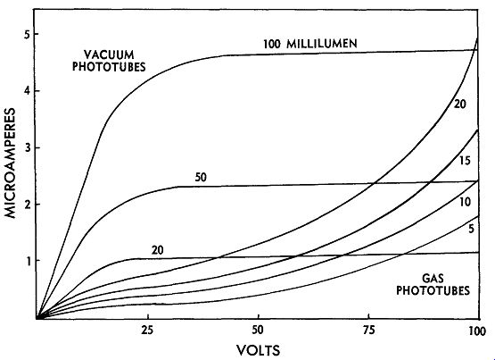
Fig. 9-1. Comparison curves of vacuum and gas phototubes.
Vacuum-type phototubes have characteristics very much like a temperature-limited diode as shown in Fig. 9-1.
This illustrates the fact that above a certain minimum voltage, further increases in plate voltage have no effect upon the cathode current. If voltages are increased beyond the 100-volt point, cathode damage will probably result, therefore, operation is generally limited to about 90 volts.
Gas phototubes show this same characteristic at plate voltage levels below the ionization point. But as soon as ionization commences, the current rises rapidly with an increase in plate voltage. If the plate voltage is increased far enough, the gas will break into a glow discharge form of ionization and damage to the photocathode will follow, so it is not recommended that they be operated in this condition. The voltage at which most gas phototubes will break into a glow discharge is in the vicinity of 125 to 150 volts, so a maximum rating of about 90 volts is also placed on the gas phototubes.
Since the useful current from a phototube is generally in microamperes, it is most important that all socket and wiring leakages be kept at a minimum. Sockets and insulation should be of the best and all forms of moisture should be kept away from them. In most cases, the tube and socket, as well as all associated wiring, should be shielded to prevent electrostatic pickup.
The source of light used to illuminate the phototube is not important as long as its general color temperature matches that of the phototube being used. The use of an optical system which spreads the light over as much of the cathode as possible is desirable, both as a means for increasing initial sensitivity and for increasing the over all life of the tube. If the light is concentrated in a small spot, there will be a loss of initial sensitivity and that portion of the cathode will become inactive prematurely.
Phototubes can be damaged by excessive illumination even when there is no plate voltage. Very high levels of illumination, such as direct sunlight, can cause a loss of sensitivity which will usually be restored after sufficient "rest" in a darkened condition.
Testing phototubes is very simple. Certain visual signs indicate whether the cathode has become poisoned due to air leaking into the bulb. The blue-sensitive cathodes turn a sooty black, while the red-sensitive types develop a mottled, or spotty, appearance. Placing the tube in series with a sensitive microammeter and a 90-volt battery and exposing the cathode to light, will demonstrate whether it is working or not. Exact sensitivities cannot be measured, of course, without a calibrated light source. But if the tube reacts to light, the only other defect it can have is a loss of sensitivity. This can be confirmed by substituting a new tube in the equipment. If this is inconvenient, the questionable tube can be tested on the bench and its output compared to that of a new tube under the same lighting conditions.
VOLTAGE-REGULATOR TUBES
Voltage-regulator tubes are constructed, in some respects, very similar to phototubes. They generally have a cylindrical cathode which is usually coated or treated in a special manner. The anode is a wire rod running through the middle of the cathode. The bulb is filled with some kind of gas.
Voltage-regulator tubes of this type depend upon the phenomenon in a gas-filled tube known as the glow discharge. When a voltage is placed between the anode and cathode of such a tube, current will not flow until the voltage is raised to a certain critical value known as the starting voltage. When this point is reached, there is a sudden flow of current accompanied by the appearance of a small glow area on the inside of the cathode cylinder.
The voltage across the tube drops considerably to a value known as the regulated value, and remains there even though the source voltage is increased further. The only change that takes place as the source voltage is raised is that more current flows through the tube. As the current through the tube increases, the glow area on the cathode also increases until it covers the entire inner surface of the cylinder. When this point is reached, the tube is said to be saturated. If the source voltage is further increased, the voltage across the tube will start to rise again. The tube is no longer in a regulated state and operation out side this region will damage the characteristics of the tube.
Voltage regulators of this type are used as shunt regulators; that is, the tube and the load are in parallel, and both are in series with a common dropping resistor from the voltage source. The value of this resistor is chosen so that at minimum load current, the voltage-regulator current is at, or near, its saturation value. When the load current increases, the voltage-regulator tube current will decrease by an equal amount and the voltage across the common series resistor will remain unchanged. This insures that the voltage across the load will remain unchanged also. If the range of current drawn by the load exceeds that of the voltage-regulator tube, which is generally from about 5 to 30 milliamperes, the tube will extinguish and the voltage will go out of control.
Voltage regulators have certain undesirable characteristics which sometimes interfere with their satisfactory operation. A knowledge of these characteristics can do much to help the user recognize them and eliminate their effects. Fig. 9-2 illustrates one of these characteristics. The small discontinuity in the curve is what is sometimes called a "pip." It is a small departure from the otherwise smooth regulation curve. As current through the tube is varied, it will sometimes be noted that the voltage goes through a discrete shift at some fixed current point. Portions of this curve may actually have a negative resistance slope. Operation at one of these points may result in oscillation in the controlled equipment. This may be at a very slow rate, in which it is known as motor boating, or it may take place at some rate which produces an RF disturbance.
The appearance of these "pips" may occur at any time in the life of the voltage-regulator tube. They are unstable and may appear at different current levels at various times. They are caused by the sudden jumping of a small portion of the glow area as it expands or contracts due to current changes through the tube. When there is a large unsaturated area of the cathode, there are more places for the glow area to jump to and so these pips are more likely to occur when the tube is operated in the lower current region of its range. Operation nearer to saturation lessens the opportunity for this type of in stability to occur.
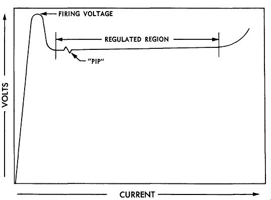
Fig. 9-2. Operating curve of voltage-regulator tubes.
Another form of instability is repeat starting. Two problems here are closely related. First, there is the matter of reliable starting every time the voltage is applied; and second, there is the matter of returning to the same regulating point each time the tube is started. The voltage-regulator tube has to be started by a considerably higher voltage than the one at which it is designed to regulate. If the starting voltage is too low, starting will be irregular.
Providing enough voltage to guarantee the tube fires vigorously is another way of also insuring that this tube will regulate at the same voltage each time it is fired.
Failure to provide this extra voltage contributes to irregular starting. This, in turn, produces an erratic repeating in the regulation point. Both problems can be materially decreased by introducing a minute amount of radioactive material into the tube. This is done in some military or industrial voltage regulators (such as the 6626 and 6627) which are quite similar to the 0A2 and 0B2.
Voltage-regulator tubes are sometimes operated in series in order to get two voltages that are regulated, one of which exceeds the ratings of a single regulator tube.
Certain problems sometimes develop when this is done, although with precautions, there is no reason why they cannot be operated in this manner.
The load current drawn from the point between the two tubes must be added to the load current drawn from the higher voltage point. This combined value must not exceed the maximum rating of either one of the tubes that are in series. Starting problems may be encountered unless resistors are placed across the tubes to insure the proper distribution of voltage when they are first turned on. If this precaution is not taken, the leakage current through the tubes will determine the voltage across them. If one tube differs significantly, and it may because this is not a controlled characteristic, one tube will start operating and drop the voltage so low that the second tube cannot start. Their leakage resistance will vary on life also, so two tubes which fire initially without any divider resistors may still get into trouble after they have been used for some hours.
Voltage-regulator tubes should never be overloaded even for very brief moments. When this occurs, there will be a shift upwards in their regulation characteristic which will then gradually drift back to normal. This shift in its regulation characteristic will take place even though the overload is only momentary and its effect will continue for some time after it is removed.
Voltage-regulator tubes of the glow-discharge type should never be operated on AC voltages, or where the polarity of the voltage is opposite to that normally applied to the tubes. In other words, voltage-regulator tubes are polarized just like electrolytics, or semiconductors.
Operating them so that reverse currents will flow through them will destroy their operating characteristics and they will become simply gas diodes.
THYRATRONS
Thyratrons are one of the most unfamiliar tubes to most people in electronics; that is, unless they have had some experience with them. They are a gas tube, featuring very high current carrying abilities. They may be designed as triodes and, in a few cases, as pentodes. In spite of their superficial similarity to vacuum tubes, they are really very different. These differences can be summed up in the following manner. The thyratron is a high current, low-voltage tube compared with most vacuum tubes which are essentially high-voltage, low-current devices. The voltage drop across a thyratron is much lower than that across a vacuum tube and, therefore, the ohmic losses are much lower, making them much more efficient for handling large amounts of power. The vacuum tube is an amplifier whose plate current is always under the control of its grid. The thyratron is more like a relay which is triggered off by the grid, but which must be reset by some other means. The grid loses all control over plate current once conduction has started. The current carriers in a vacuum tube are electrons, whereas in a thyratron they are ions.
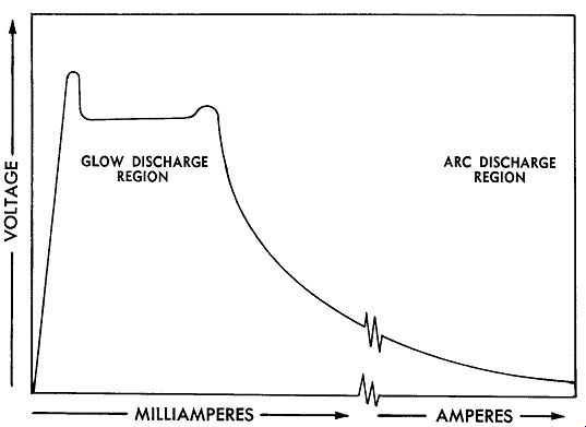
Fig. 9-3. A curve showing the glow-discharge and arc-discharge regions of
voltage-regulator tubes.
In discussing voltage-regulator tubes, the glow-discharge phenomenon was discussed. If a tube is in a glow discharge condition and the current is increased beyond the saturation point, the voltage across the tube will rise.
If current through the tube is increased still further, a point will be reached where the voltage drops suddenly and the current rises sharply. The entire interior of the tube will then glow, and it is then said to be in the arc-discharge region. This is illustrated in Fig. 9-3. If the current is increased still further, it will rise into the ampere region while the voltage drop across the tube remains very low and substantially unchanged. This is the region in which thyratrons and gas rectifiers work.
In the arc discharge, conditions are very different from those existing in a vacuum tube. Current conduction is entirely by means of ions. Electrons released by the cathode are merely used as bullets to bombard the gas atoms and provide more ions. Once initiated, the arc can neither be controlled in amplitude, nor stopped by the grid. If a negative voltage is applied to the grid, it will attract positive ions which will form a shield around it and thereby cancel its effect. Similarly, if a positive voltage is applied to the grid, negative electrons will be attracted, neutralizing the effect of the grid upon the arc discharge.
The grid of a thyratron serves only one purpose-to determine the conditions under which the tube will fire.
For every value of grid voltage, there is a corresponding value of plate voltage that will just fire the tube. This is known as the "critical characteristic" for the tube and is illustrated in Fig. 9-4. The curve is shown as an area rather than as a single line because of variations in this characteristic due to temperature, aging, and other factors which will be discussed. The critical characteristic may lie completely within the negative-control region; or it may lie partly or entirely within the positive-control region.
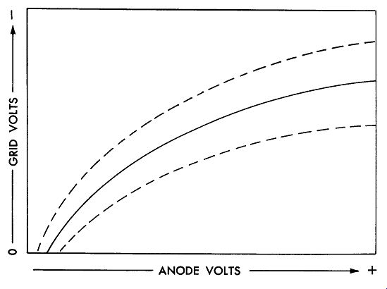
Fig. 9-4. Critical characteristic curve of a thyratron.
Most thyratrons are triodes; however, a few have an additional element known as a screen grid. One purpose of the screen grid is to reduce the current drawn by the grid. By placing the screen grid at cathode potential, the control grid is shielded from much of the ionic current.
This raises control-grid impedance so that this type of thyratron can be used directly with such high impedance devices as phototubes.
The particular type of gas used in a thyratron makes quite a difference in its individual characteristics. Three types of gases are normally used-hydrogen, the inert gases (neon, argon, and xenon), and mercury vapor.
Occasionally, combinations of two or more gases will be used to produce a compromise of characteristics. Generally speaking, the lighter gases are less temperature sensitive, require less warm-up waiting, and will operate at higher frequencies. Mercury vapor, on the other hand, permits higher current and voltage ratings. That is why mercury vapor is used in most of the heavy duty thyratrons.
Ionization and Deionization Time
As mentioned earlier, a thyratron operates by ionic conduction rather than by current conduction between its anode and cathode. Ions are atoms which have lost or gained an electron, so they carry either a positive or a negative charge. Electrons are much smaller than ions and are almost weightless. Ions, on the other hand, are large and heavy. The simple laws of mass and energy apply to these particles of matter just as they do to much larger particles. Electrons can be easily stopped or started, but not the heavier ions. It takes time to get them moving, and like any other heavy body, once they are moving, they cannot be stopped instantly.
Ionization is started when a few electrons from the cathode start moving rapidly toward the anode under the effects of the anode potential. These electrons act like bullets and soon collide with the bigger gas atoms in the space between the cathode and the plate. Electrons are knocked out of these atoms and they become ions. Because they are no longer neutrally charged, but now have a positive charge, they begin to move away from the positively charged plate. As these ions gather speed, they run into more atoms and, as a result, additional ions are formed. Thus, a chain reaction gets underway and soon the entire space is filled with ions and electrons moving rapidly toward the plate and the cathode. This is the condition within the arc discharge when complete ionization has taken place.
When the anode voltage is removed, these ions keep right on going for awhile. With no accelerating force to supply the electron bullets needed to make new ions, the old ions begin to recapture their lost electrons. They then become neutral again and start to slow down. Eventually, all stray electrons have recombined with an ion and the gas is said to be deionized. This is the process which must take place each time a thyratron fires and before it can fire again.
Since weight obviously governs the acceleration and deceleration of atoms in a gas, the lighter the gas, the less time it will take to ionize and de-ionize. For this reason, hydrogen thyratrons have the shortest ionization and de-ionization time, and mercury vapor has the longest.
Temperature also influences the ionization time. Again, the lighter gases are much less affected. Mercury vapor is especially sensitive because, as the temperature rises, more mercury is vaporized and the gas becomes more and more crowded with mercury atoms. The electrons and atoms thus collide more frequently and have greater difficulty acquiring enough velocity to produce ions. This slows down both the ionization and deionization processes.
Although the lighter gases are little affected by temperature, they do suffer from a phenomenon known as "gas cleanup." This is a reduction in gas pressure due to the combining of the gas with the elements of the tube itself, which eventually makes the tube unusable. This is the most common cause of failure in this type of thyratron.
Gas cleanup can be greatly increased or decreased by certain circuit conditions. When the current passing through the tube is very high just before the anode voltage is switched off, and when there is a large and sudden increase in the inverse anode potential immediately after the interruption, gas cleanup proceeds at a very rapid rate. This can be greatly retarded by observing certain precautions in circuit designs. Small reactive elements are connected in series with the anodes, tending to delay the rise rate of the inverse voltage. This will give greatly prolonged tube life.
Waiting Time
Another important precaution which must be observed with thyratrons is the matter of "waiting time." This is the length of time after the tube filament is turned on before anode potential may be applied. When a thyratron is first turned on, its cathode is cold. If anode voltage is applied at this time, nothing will happen because there are no electrons to start the ionizing process. As the cathode heats, some electrons will become available, but they will be immediately drawn toward the anode. As ions form, they will start moving in the direction of the cathode, and will meet with little opposition because the space is relatively free of other fast moving particles. By the time they reach the cathode, they will be traveling rather fast. Unless there is a large cloud of free electrons immediately surrounding the cathode to slow them down, they will crash into the cathode surface with sufficient force to destroy its emitting surface in a fraction of a second.
In order to prevent this sudden destruction of thyratrons, the heater must be turned on before the anode voltage is applied and sufficient time must be allowed for the cathode to reach full operating temperature. The rare gas thyratrons require less waiting time than do the mercury vapor types. In the case of the latter types, enough time must be allowed to permit the condensed mercury to evaporate. This requires that the bulb temperature itself must be raised to the vapor point of mercury at its coldest point.
Before installing mercury-vapor thyratrons for the first time, it is a good idea to hold them base downward and then to swing them in a wide arc several times. This is to make certain that all of the liquid mercury is in the base of the tube and that none of it has lodged on insulators or other supporting members of the tube where it may cause flash-over and damage to the equipment or the tubes. During shipment, the mercury scatters all through the tube, so it is necessary to take this precaution to avoid unnecessary arcing and sputtering. When these thyratrons are taken out of service and are to be stored, they should be left standing base down, so that when re installed they will operate properly.