Although no industry standards have been established, it is generally agreed that high-fidelity reproduction entails a frequency response that is flat within ±1 dB from 20 Hz to 20 kHz, approximately, and with a harmonic-distortion figure of less than 1 percent at maximum rated power output. We will find that harmonic-distortion (HD) and intermodulation-distortion (IM) values usually have the same order of magnitude. However, there are certain types of system defects that cause IM distortion to increase much more rapidly than harmonic distortion as the power output is increased. Various types of distortion and pertinent measurement techniques are explained subsequently. An AM tuner is a refined version of a conventional AM radio receiver, but without an audio amplifier and speaker. A hi-fi AM tuner differs from an ordinary AM tuner primarily in its greater bandwidth; a hi-fi unit also has certain minor refinements. In most cases, a hi-fi AM tuner is provided as a section of a hi-fi am/fm receiver (see Fig. 1-1). Few hi-fi AM tuners are individually merchandised because there is seldom more than one hi-fi AM broadcast station in a given locality.
Most current-model hi-fi AM tuners are solid state, although many tube-type tuners are still in use. Solid state design is usually on a transistor-for-tube basis, except for systems employing IC packages. Printed circuit construction is generally utilized. The super heterodyne configuration is universal, although design details vary considerably. A typical arrangement utilizes four transistors and a diode detector; two IF stages are used, with no RF amplification (no pre-selection). In economy-type designs, we may find that a single transistor does double duty by operating as an oscillator and converter. Integrated circuitry is used in the IF section by some manufacturers. Deluxe AM tuners are provided with at least one stage of pre-selection to improve selectivity and image rejection. Common trouble symptoms caused by defects in hi-fi AM tuners are as follows:
1. Dead tuner.
2. Weak output.
3. Distorted output.
4. Incorrect dial indication.
5. Intermittent operation.
6. External interference.
7. Poor selectivity.
8. Drifting off-frequency.
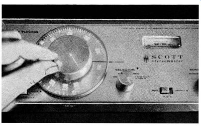
Fig. 1-1. Typical hi-fi am/fm tuner.
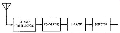
Fig. 1-2. Block diagram of a typical AM tuner.
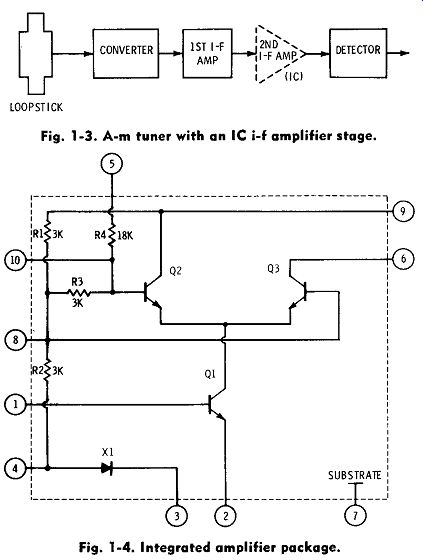
Fig. 1-3. AM tuner with an IC IF amplifier stage.
Fig. 1-4. Integrated amplifier package.
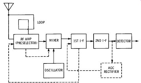
Fig. 1-5. Block diagram of an elaborate AM tuner.
GENERAL DISCUSSION
A block diagram of a typical AM tuner is shown in Fig. 1-2. This arrangement employs a preselector stage (RF amplifier), a converter, an IF stage, and a diode detector. The tuning range is from 530 to 1620 kHz; no short-wave bands are provided. Note that a converter stage has a single transistor (or tube) that does double duty as an oscillator and mixer. On the other hand, some AM tuners use two transistors in this section-one transistor operates as an oscillator, and the other operates as a mixer. An external antenna is utilized in the arrangement of Fig. 1-2. This circuit is resonated by means of a tuned loopstick; an external antenna is not required if the prevailing signal strength is comparatively high. The gain of this type of tuner is not as great as in designs that have two IF stages and no preselector stage. On the other hand, a preselector stage minimizes the possibility of image interference.
Another arrangement for an AM tuner is shown in Fig. 1-3. It includes two transistors, an integrated circuit, and a diode detector. No preselector is provided, and the converter transistor is driven directly by a loopstick antenna. Since ample system gain is available, no provision is made for connection of an external antenna. The second IF stage employs an integrated circuit instead of a conventional transistor. An integrated circuit (IC) includes semiconductor devices and resistors, as exemplified in Fig. 1-4. An IC package may also include fixed capacitors; we will find that all IF IC packages are connected externally to tuned coils or transformers. A diode detector in an AM tuner often does double duty as a signal detector and agc rectifier; in deluxe designs, however, a separate agc rectifier diode is provided.
Fig. 1-5 shows a block diagram for an elaborate AM tuner. This arrangement employs five transistors, a diode detector, and a diode agc rectifier. Reception is provided by a built-in loop, which may be supplemented by an external antenna, if desired. The incoming signal is stepped up by a preselector stage, followed by a mixer-oscillator section for frequency conversion. Note that the first IF stage is agc-controlled; this transistor does double duty in that it provides IF amplification and also operates as an amplifier for the age current. Thus, amplified age current is applied to the rf-amplifier transistor. The mixer transistor is biased by age current that has been amplified through the rf-amplifier transistor.
Transistor Versus Tube-Type Tuners
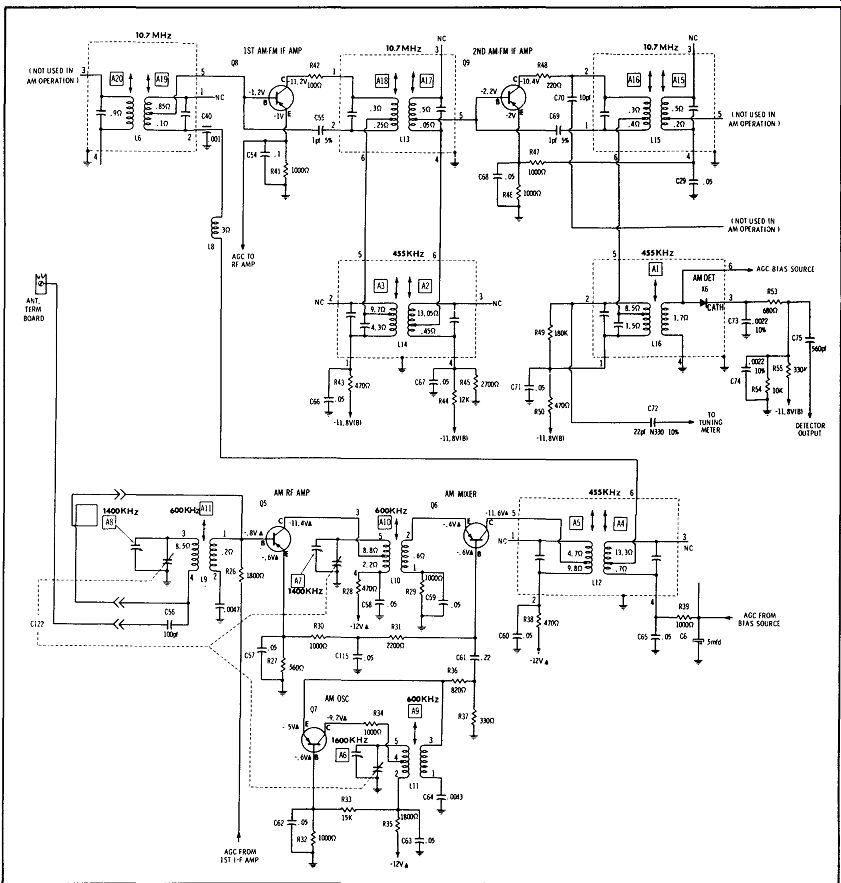
Fig. 1-6. Partial schematic of a transistor AM tuner.
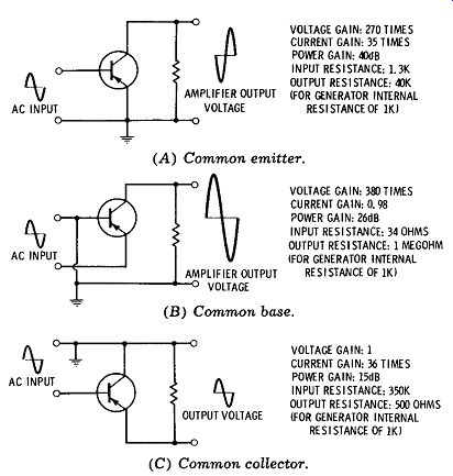
Fig. 1-7. Transistor circuit parameters. (A) Common emitter. (B) Common base.
(C) Common collector.
Transistors provide several advantages in high fidelity systems, among which we may note their small size, comparatively low power consumption, reliability, and absence of microphonics. Transistors are basically low-impedance devices and are relatively immune to pickup of stray fields from power supplies or other ac circuitry. Since a transistor has no filament or heater, it cannot develop internal hum.
Fig. 1-6 shows a schematic for a transistor AM tuner.
It consists of an RF amplifier, local oscillator, mixer, two stages of IF amplification, and a diode detector.
Agc bias current is applied to the bases of the RF amplifier, mixer, and first IF transistors. This agc bias current is introduced at the base of the first IF transistor; in turn, stepped-up age bias current is fed from the emitter of the first IF transistor through a switching section to the base of the RF amplifier transistor. Stepped-up age bias current is then applied from the emitter of the RF amplifier transistor to the base of the mixer transistor.
The second IF transistor in Fig. 1-6 operates constantly at maximum gain. As is customary in combination receivers, AM and fm transformers are operated in series (see L13/L14 and L15/L16). This series mode of operation is feasible because the intermediate frequencies are widely different in AM and fm operation. Thus, the impedance of a 10.7-MHz winding is so small in 455-kHz operation that the winding "looks like" a short-circuit. The transistors operate in the common-emitter (CE) configuration, with the exception of the oscillator and mixer transistors, which operate in the common-base (CB) con figuration. Note that so far as DC current amplification in the age system is concerned, the first IF transistor and the rf-amplifier transistor operate in the common-collector (CC) configuration. Fig. 1-7 shows the basic configurations and their relative performance characteristics.
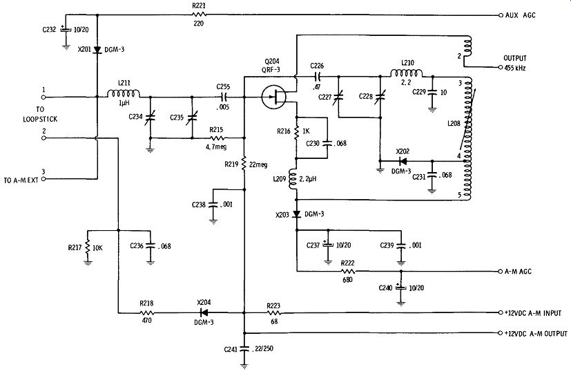
Fig. 1-8. Input section of an AM tuner using an FET.
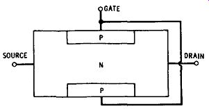
Fig. 1-9. N-channel
junction FET.
In addition to junction transistors and IC pack ages, we also find field effect transistors (FETs) in some AM tuners, as exemplified in Fig. 1-8. An FET is similar to a vacuum tube in that it has an extremely high input impedance. As shown in Fig. 1-9, a field-effect transistor has three electrodes, called the drain, the gate, and the source; these are comparable respectively to the plate, grid, and cathode of a vacuum tube. An n-channel junction FET is exemplified in Fig. 1-9; a positive voltage is applied to the drain, and a negative control voltage is applied to the gate. When the gate voltage is zero, there is current from the source to the drain, as shown in Fig. 1-10. However, an increasing negative voltage on the gate reduces current because of the restricting action of the depletion layer. In normal operation, the gate is reverse-biased, so that the operation is quite similar to that of a triode tube. A p-channel FET operates in the same manner, except that the bias voltages are reversed. This is the same distinction that is observed in pnp and npn junction transistors.
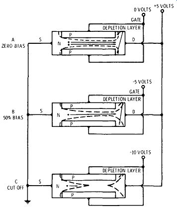
Fig. 1-10. Effect of bias on an FET.
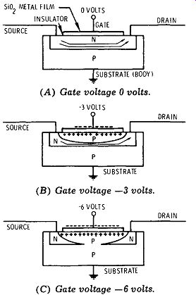
Fig. 1-11. N-channel depletion MOSFET.
Another type of FET, called the MOSFET, is designed so that at zero gate voltage, drain-current conduction either will or will not occur. If a MOSFET permits current at zero gate voltage, it is called a depletion type; on the other hand, if current is stopped at zero gate voltage, it is called an enhancement type. Fig. 1-11 shows the cross-section of a depletion-mode MOSFET (n-channel version). Note that it has an additional connection called the substrate, which is usually connected to ground. "Channel" terminology derives from the fact that when the device is conducting, a channel of n-type material occurs between the n-type drain and the source. The basis of MOSFET operation is the capacitance formed by the metal gate, the silicon-dioxide insulator, and the silicon semiconductor.
Since an ideal capacitor conducts no direct current, the gate electrode has zero leakage current whether a positive or a negative signal voltage is applied. On the other hand, the grid of a triode tube draws current when driven positive. When the gate voltage is zero, as shown in Fig. 1-11A, the existing n-channel conducts electrons from the source to the drain. If a negative gate voltage is applied, the MOS capacitor charges. This causes holes to be drawn toward electrons on the gate, thus forcing electrons out of then channel, as shown in Fig. 1-llB. Because the channel is now smaller, there is less current from source to drain. If sufficient negative voltage is applied to the gate, enough electrons are forced out of the channel to produce pinch-off, as shown in Fig. 1-11C. An npn junction is formed, but it does not conduct current because the pn junction is reverse-biased: The enhancement type of MOSFET (Fig. 1-12) operates in an opposite manner. When the gate voltage is zero, there is no current-conducting channel.
On the other hand, when the gate is positive, electrons are drawn toward the gate, which sets up an n-channel. There is then current from source to drain in accordance with the value of positive gate voltage that is applied. Since the input impedance to the gate is extremely high, static electricity from strong stray fields can build up enough voltage to damage an FET when it is not connected into a circuit. Therefore, the leads are usually short-circuited until the FET is connected into its circuit. Most hi-fi assemblies employ printed or plated circuits; a spectacle loupe such as is illustrated in Fig. 1-13 is helpful for inspecting connections, and also in localizing defects such as cracks in PC conductors.
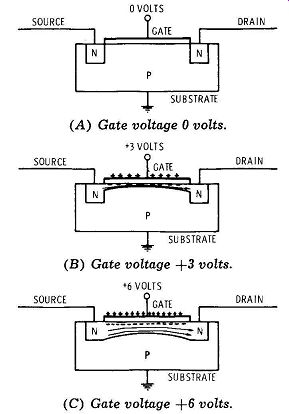
Fig. 1-12. N-channel enhancement MOSFET.
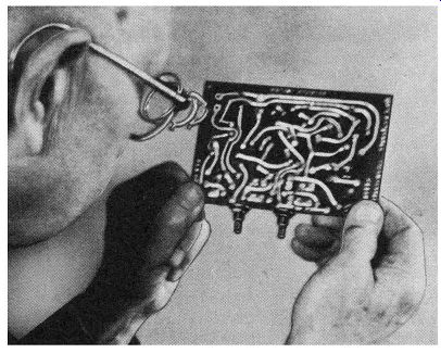
Fig. 1-13. Spectacle loupe aids inspection of PC boards.
Next, let us consider the tube-type AM tuner con figuration shown in Fig. 1-14. This arrangement em ploys a stage of pre-selection (RF amplifier), a converter, a stage of IF amplification, and a diode detector. A bandwidth (bandpass) switch is provided, which operates in the rf-amplifier input and output circuits. This switch provides a choice of an audio-frequency bandwidth of either 7 kHz or 14 kHz. Although an af range of 7 kHz does not provide hi-fi response, narrow-band reception is desirable for tuning in weak or distant stations with a minimum of interference. On the other hand, an af bandwidth of 14 kHz provides the maximum available fidelity from hi-fi AM broadcast stations. When wide-band reception is utilized on conventional AM station signals, a 10 kHz beat note is developed; this beat note results from the fact that the stations have carrier allocations at 10-kHz intervals. Such 10-kHz beat notes are trapped by a high-Q filter (see T5-C7 in Fig. 1-14). The RF bandpass in Fig. 1-14 is controlled by switching resistance into or out of the tuned circuits. Thus, a 27-ohm resistor, R204, can be switched into the RF grid-input circuit; also, an 18-ohm resistor, R210, can be effectively switched (unbypassed) in the RF plate-output circuit. Note that an af band width of 7 kHz corresponds to an RF bandpass of 14 kHz, and an af bandwidth of 14 kHz corresponds to an RF bandpass of 28 kHz. In other words, the RF amplifier processes both upper and lower sidebands in an RF signal. We measure bandpass values between the 70. 7 percent amplitude points on the frequency response curve, as shown in Fig. 1-15. The way in which signal voltage and RF bandpass change with values of circuit resistance is seen in Fig. 1-16 for a basic example. A leaky capacitor can change the circuit resistance.
Technician apprentices often suppose that the selectivity of a tuner depends entirely upon its band pass. However, selectivity also depends to an appreciable extent upon the steepness of the frequency response curve. For example, if the bandpass is correct, but a tuner has a 50 percent response at the carrier frequency of an adjacent-channel station, it is obvious that objectionable interference will result.
An ideal response curve would be rectangular ( see Fig. 1-17). Although the ideal response cannot be obtained in practice, it can be approximated by suit able tuner design and correct alignment of the tuned circuits. The use of a double-tuned transformer with suitable coupling provides a double-humped response that approaches a flat-topped response, as seen in Fig. 1-18. The comparative steepness of response curves for a single tuned circuit and a tuned trans former (two identical, coupled, tuned circuits) is shown in Fig. 1-19. Troubles in tuned circuits are analyzed with the aid of a signal generator.
Automatic Volume Control
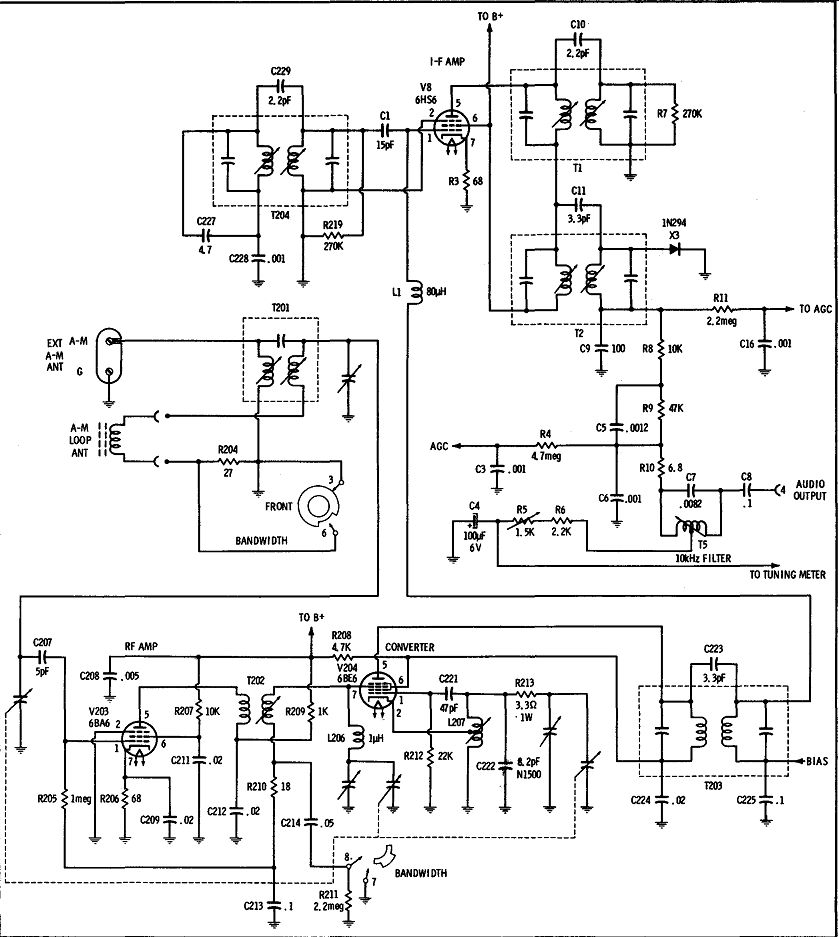
Fig. 1-14. Tube-type AM tuner configuration.
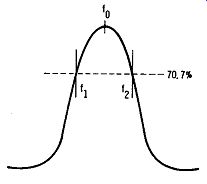
Fig. 1-15. Bandpass is defined as f2 - f1 hertz.
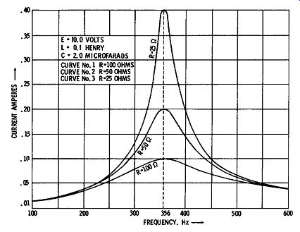
Fig. 1-16. Three frequency-response curves for an LCR series-resonant circuit.
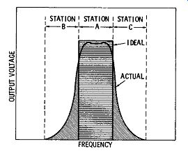
Fig. 1-17. Selectivity depends on the steepness of the frequency-response
curve.
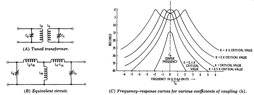
Fig. 1-18. Increased bandwidth is obtained by coupling two tuned circuits.
(A) Tuned transformer. (B) Equivalent circuit. (C) Frequency-Response curves
for various coefficients of coupling (k).
Automatic volume or gain control (avc or agc) denotes an arrangement for maintaining the output from an AM tuner at a comparatively constant level, in spite of variation in strength of an incoming signal.
The basic age circuit comprises a signal rectifier and low-pass filter; this signal rectifier is very often a diode that does double duty as a detector. An RC low-pass filter is always used because of its economy and because it serves the purpose as effectively as an LR or LCR filter. The output from this low-pass filter is a DC voltage ( or DC current), which is applied to the grid of a controlled tube, or to the base of a transistor. Functionally, the low-pass filter permits the DC output to change level when the incoming signal varies in strength, but prevents the DC output from changing as the modulation envelope of the signal rises and falls. That is, the time constant of the RC filter is chosen sufficiently long that the filter cannot respond to the short rise-and-fall intervals in the modulation envelope. Defects in age filter components produce distinctive trouble symptoms.
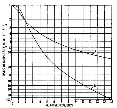
Fig. 1-19. Skirt of frequency-response curve.
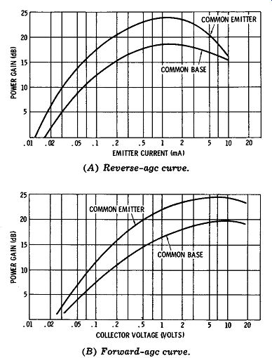
Fig. 1-20. Typical age characteristic curves. (A) Reverse-age curve. (B)
Forward-age curve.
An agc circuit normally supplies zero current to a controlled tube, since a grid is effectively an open circuit. Thus, the gain of the tube is controlled by the value of the agc voltage. Reverse agc is always utilized; in other words, the agc voltage becomes more negative as the signal strength increases. On the other hand, the gain of a transistor is controlled primarily by variation of bias current; that is, the base of a transistor draws DC current from the age line. Since the input resistance of the base is very low, a very small change in voltage produces a large change in current; this is one of the reasons that we characterize a transistor as a current-operated device. Also, any change in base current is multiplied by the beta value of the transistor in the collector circuit. This is another one of the reasons for regarding a transistor as a current-operated device.
Transistors differ from tubes in that they may be controlled either by reverse age, or by forward age.
When reverse agc is used, an increase in signal strength results in reduction of the base current. However, when forward agc is used, an increase in signal strength results in an increase of base current.
Some types of transistors are controlled to best ad vantage by reverse agc; others provide better control with forward age. In either case, the designer em ploys the mode that gives the more gradual cutoff characteristic. A sharp cutoff characteristic is undesirable because it curves rapidly and may give rise to cross-modulation interference. Whenever forward agc is used, we will find a substantial amount of resistance present in the collector circuit. This series resistance is required because forward-age action entails transistor saturation, and saturation takes place at very low collector voltage. In other words, when the base current is very high, the collector current is also very high. In turn, a large voltage drop is developed across the series resistance in the collector circuit, causing the collector-emitter voltage to fall to a very low value. Normal age characteristics are shown in Fig. 1-20.
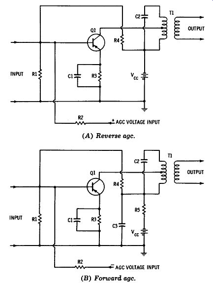
Fig. 1-21. Schematics of age circuits. (A) Reverse agc. (B) Forward agc.
Basic examples of reverse-age and forward-age arrangements are shown in Fig. 1-21. Note that a series resistor, R5, is included in the collector circuit of the forward-age arrangement. In Fig. 1-22, we see an IF stage with a detector that does double duty as an agc rectifier. The agc current is filtered by R1 and C2; as the signal strength increases, the base current decreases-that is, reverse agc is employed in this example. Conventional transistors are triode devices, and many of them require neutralization to avoid instability due to regeneration or oscillation.
Thus, signal voltage is fed back in reverse phase to the base of Q1 from T2 via neutralizing capacitor C5.
It is easy to confuse neutralizing trouble with age trouble, because defects in a neutralizing circuit are associated with large changes in gain. To anticipate subsequent discussion, age trouble causes little or no change in bandpass, whereas neutralizing trouble causes a large change in bandpass.
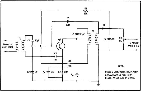
Fig. 1-22. I-f stage and detector, with age and neutralizing circuits.
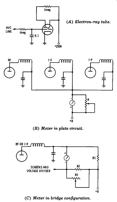
Fig. 1-23. Tuning-indicator arrangements. (A) Electron-ray tube. (B) Meter
in plate circuit. (C) Meter in bridge configuration.
Tuning Indicators
A tuning indicator is provided on nearly all hi-fi AM tuners; it indicates when the unit is tuned exactly to a station carrier. Thus, a tuning indicator assists nontechnical persons in avoiding distortion due to sideband cutting. Technicians also find tuning indicators useful during alignment procedures. A tuning indicator may be some type of electron-ray tube, or a panel meter. We find electron-ray tubes mounted near the tuning scale, or alternatively, a miniature electron-ray tube may do double duty as a pointer on the tuning scale. An electron-ray (eye) tube is ordinarily energized from the age line; occasionally, a stage of DC amplification may be provided for optimum sensitivity on weak signals. Tuning meters are also energized from the age line, although the meter is occasionally connected into the plate or screen circuit of an age-controlled tube (see Fig. 1-23). If a zero-center or zero-left reference is utilized, the meter is connected into a bridge circuit with a zero-adjustment potentiometer.
Signal Sources for Troubleshooting
Preliminary troubleshooting of an AM tuner often requires the localization of a dead stage. This can be done by means of either signal-tracing or signal substitution techniques. In either method, it is desirable to have a controllable source of modulated RF signal. An economy-type AM generator is suitable, inasmuch as we are not concerned with accurate frequency or signal-level measurements. Even a simple noise generator or harmonic oscillator will serve the purpose. If signal injection is utilized, the tuning meter will serve as an indicator; however, if the AM tuner does not have a tuning meter, we can connect a DC voltmeter to the age line. Signal injection is started at the detector input, and proceeds back step by step until the dead stage is located. Note that a dead local oscillator does not show up in a test made with a noise generator or harmonic oscillator. For this reason, tests with an AM generator are sometimes more conclusive. In signal-tracing tests, we apply the signal at the antenna-input terminals, and check its progress through the AM tuner step by step with a suitable indicator. An oscilloscope used with a low-capacitance probe is the most useful type of indicator.
Signal-tracing and signal-substitution tests will sometimes pinpoint a defective component-however, this type of test often serves only to localize the defective section. DC voltage measurements are usually made to close in on the defective component.
Resistance measurements and continuity checks are also helpful in various situations. After a defective component is replaced, and the hi-fi tuner is apparently operating normally, two basic proof-of-performance tests should then be made. First, the frequency response can be checked as indicated in Fig. 1-24. An accurate test requires a good-quality signal generator capable of hi-fi external modulation; a good-quality audio oscillator is also required that has good waveform and flat output over its en tire range. If the AM tuner has true hi-fi frequency response, the ac VTVM reading will not vary by more than 1 dB over the range from 20 Hz to 20 kHz.
It is customary to use 30 percent modulation in this test.
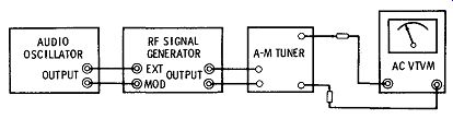
Fig. 1-24. Check of frequency response.
Unsatisfactory frequency response can be caused by several types of defects. For example, one or more of the RF or IF tuned circuits may be misaligned. In such a case, careful realignment in accordance with the tuner service data will correct the frequency response. However, capacitor defects can cause poor frequency response also, although the alignment is correct. For example, a defective neutralizing or by pass capacitor can seriously affect the frequency response. Again, if the detector load resistor increases in value, the high-frequency response will be impaired. In tube-type tuners, a small coupling capacitance may be provided between primary and secondary of the IF transformers (see C223 and C11 in Fig. 1-14). If one of these capacitors becomes defective, the bandwidth will be seriously impaired.
Next, we should note that a hi-fi AM tuner requires a separate test for harmonic distortion. In other words, frequency response is not related to harmonic distortion. Harmonic distortion can be measured with the test setup shown in Fig. 1-25.
The basic test is made with the audio oscillator set to a frequency of 1 kHz, and with an output level that modulates the signal generator 30 percent. A fairly high output is customarily used from the signal generator, such as 100,000 µV. If the AM tuner is operating properly, its harmonic distortion will be well below 1 percent. Note that if your RF signal generator does not have a meter to indicate modulation percentage, you can feed the generator output into a scope, and evaluate the screen pattern, as exemplified in Fig. 1-26. Since the ratio of B - A to B + A is equal to 0.65 in this example, the modulation percentage is 65 percent. A harmonic-distortion meter is illustrated in Fig. 1-29.
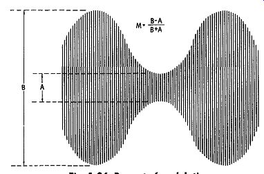
Fig. 1-26. Percent of modulation.
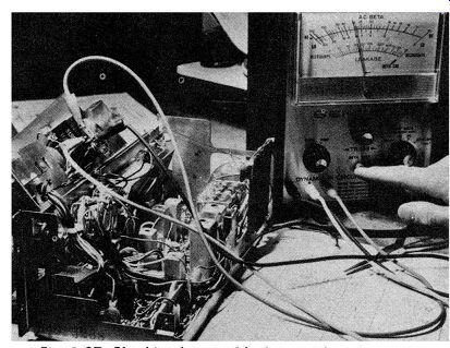
Fig. 1-27. Checking beta and leakage with an in-circuit transistor tester.
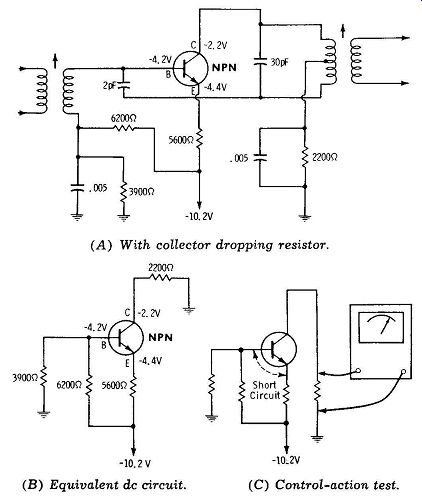
Fig. 1-28. Transistor quick-check with voltmeter. (A) With collector dropping
resistor.
(B) Equivalent DC circuit. (C) Control-action test.
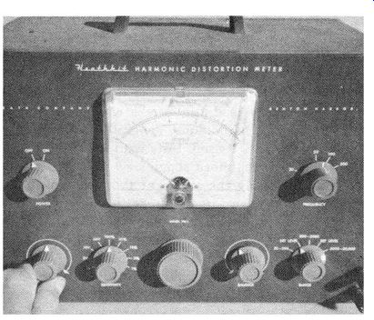
Fig. 1-29. Harmonic-distortion meter.
In case a harmonic-distortion test shows that objectionable distortion is present, we look for defects that can cause nonlinear operation. Incorrect bias voltages are suspected first, and are often caused by leaky capacitors. Defective transistors can also cause excessive harmonic distortion. In most situations, abnormal terminal voltages are produced by transistor defects. However, if the normal DC voltage values are not known, an in-circuit transistor tester will give a useful preliminary test (see Fig. 1-27). In many cases, a simple control-action check can be made with a voltmeter to determine if a transistor is in good operating condition. With reference to Fig. 1-28, a resistor is present in series with the collector circuit. We connect a DC voltmeter across the collector resistor, and short-circuit the base and emitter terminals. If control action is normal, the voltmeter reading drops to zero.
TROUBLESHOOTING PROCEDURE
As noted previously, the technician is usually concerned with an am/fm stereo combination. Fig. 1-30 shows a block diagram of a typical chassis. If AM reproduction is defective, but fm reproduction is normal, we know that the trouble will be found in the AM converter or detector section. On the other hand, if both AM and fm reception are defective, the trouble will be found in the IF or audio sections. In case the phono operation is also defective, we know that the trouble is located in the audio section. however, if phono operation is normal, with both AM and fm operation faulty, it is evident that the trouble is located in the first or second IF section. A dead stage is easily localized by signal-injection tests at the bases of the transistors with a noise generator, harmonic oscillator, or modulated-RF generator. Apprentice technicians should be reminded to make certain that a series capacitor is included in the "hot" lead from a signal source, to prevent DC drain-off from transistors under test.
Weak stages are localized to best advantage by means of stage-gain measurements. A DC voltmeter is connected at the detector output, and a generator signal is injected at the bases of successive transistors. The age line must be clamped to obtain accurate output-voltage indications. In the case of IF stages, a comparative check is sufficient; that is, inject the IF signal at the detector input and note the voltmeter reading-then inject the IF signal at the base of the second IF stage and observe the increase in volt meter reading. Finally, inject the IF signal at the base of the first IF stage and again observe the increase in voltmeter reading. The ratios of the successive readings should be in the same order of magnitude. A significantly low ratio points to a weak stage. The gain of an RF stage is not quite as great as that of an IF stage in normal operation, and the gain of a converter stage is about half as much.
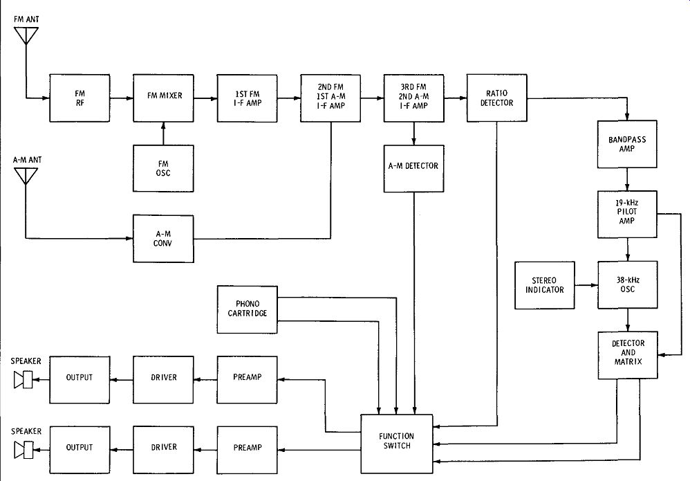
Fig. 1-30. Block diagram of a typical am/fm stereo chassis.
Distortion is most likely to occur in a high-level stage, such as the last IF amplifier. However, regeneration can cause distortion in low-level stages. In some cases, distortion is the result of high-level ripple on the B+ line. The detector stage occasionally produces distortion if a load resistor increases greatly in value. If regeneration is present, the distortion will increase at low values of age override voltage.
The reason for this response is that the beta of a transistor or the mu of a tube increases when the age voltage is reduced. In turn, regeneration and distortion are increased. To localize a regenerative stage, it is advantageous to check the bandwidth step-by-step with a signal generator; the tuning meter may be used as an indicator, as noted previously. We start by injecting the signal at the base of the last IF transistor, and noting the 70.7 percent frequencies. Then we proceed to the next-to-the-last stage, and so on. A regenerative stage shows up as subnormal bandwidth between the 70.7 percent frequencies.
Intermittent troubleshooting is often the most time-consuming and baffling type of job that must be confronted by the technician. An intermittent is a trouble condition that is not continuously present, but switches in and out or varies in degree from time to time. Thermal intermittents are actuated by heat; for example, a thermally intermittent resistor may change value suddenly when its temperature passes a certain critical level. Another thermally intermit tent resistor may change value smoothly but rapidly as its temperature increases. Defective components in this category can be localized to best advantage by varying their temperature with a heat lamp followed by a spray coolant.
In a puzzling troubleshooting situation, the value of a thorough visual inspection cannot be overemphasized; there is always a tendency for the highly skilled technician to overlook the obvious possibilities, such as a broken conductor inside an insulated lead, or frayed insulation on interconnecting leads.
Cracked PC conductors and cold-soldered connections (Fig. 1-13) are common causes of intermittent operation. Line cords should be checked, particularly in installations that employ long extension cords. Since the voltage drop produced by an extension cord aggravates any line-voltage fluctuation that occurs, monitoring should be done at the AM tuner-not at the power outlet. If the supply voltage fluctuates sufficiently, the local oscillator can "drop out" mysteriously when a refrigerator starts up, or when a disposal unit is turned on.
Other common troublemakers are worn switches, erratic controls, incompletely inserted plugs, defective capacitors, overheated power transformers, poorly grounded coil shields, loosely mounted PC boards, and failing rectifiers. Experienced technicians know that it is easy to overlook the soldering of a connection after a component has been replaced and its connecting wires inserted in eyelets or hooked around lugs. Mechanical intermittents of this general type can often be localized by "tapping" procedures.
In most cases, the intermittent condition becomes increasingly responsive when the trouble area is approached. Case histories show that an AM transformer can develop leakage or a short-circuit between windings, or a winding can become intermit tent. Try pushing on the IF transformer terminals, and press against the shield can while listening to the signal output. In most cases, a defective trans former tunes broadly, and several turns of the core will be required to change the signal level noticeably.
As a general rule, transistors are very long-lived, and tend to fail catastrophically. However, there are also the exceptions that prove the rule. For example, all experienced technicians can recall an occasional encounter with an intermittent transistor. The intermittent often develops as an "on-or-off" switching action. Again, an intermittent transistor can fluctuate between normal operation and weak operation.
A defective transistor in the IF section can produce regeneration and can masquerade as a defective neutralizing capacitor. If stations can be tuned in only at the high or at the low end of the band, the oscillator transistor is a ready suspect. Nearly all transistor defects are associated with changed values of terminal voltage. Technician apprentices may discover that a transistor trouble symptom can be "cured" by operating the circuit with more or less overvoltage. However, it is very poor practice to "troubleshoot" a circuit by providing excessive operating voltage; an imminent catastrophic failure can be anticipated under these conditions.
Troubleshooting an interference symptom requires an accurate AM generator and starts with a check of the overall frequency-response curve for the tuner. Sometimes you will find that interference is the result of "cockpit trouble" in which a semi-technical customer has attempted to align the tuner by ear. In such case, it is only necessary to follow the alignment procedure specified in the receiver service data. However, the majority of interference symptoms will be tracked down to defective components such as leaky or open capacitors, shorted coil turns or layers, a damaged built-in antenna, and so on.
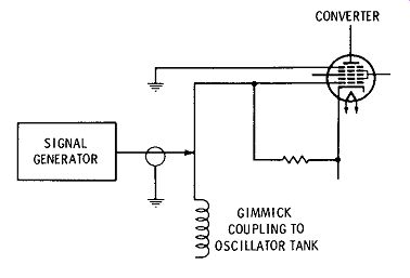
Fig. 1-31. Substituting signal generator output for the local oscillator
signal.
ANALYSIS OF COMMON SYMPTOMS
An analysis of the common trouble symptoms listed earlier in this Section is presented in this section.
1. Dead Tuner
Any defect that completely stops the signal will result in a "dead tuner" symptom. It is sometimes helpful to evaluate the noise level of the system with the volume control turned to maximum. For example, the noise level will be higher if the RF stage is dead, than if the last IF stage is dead. In the case of a tube-type tuner, the tubes should be checked first.
Possible causes of a dead AM tuner are as follows:
a. Defective or erratic function switch (see Fig. 1-30).
b. Oscillator drop-out.
Check by substituting a generator signal, as shown in Fig. 1-31.
c. Shorted capacitor, such as C73 in Fig. 1-6.
d. Open capacitor, such as C75 in Fig. 1-6.
e. Leaky capacitor, such as C69 in Fig. 1-6.
f. Defective transistor; make control-action test, measure DC terminal voltages, or use in-circuit transistor checker.
g. Break in PC wiring; make voltage measurements and continuity checks of suspected conductors.
As noted previously, preliminary localization of a dead stage is made on the basis of signal-tracing or signal-substitution tests. If the entire tuner is dead, the trouble is most likely to be found in the detector stage-for example, X6 in Fig. 1-6 might be open or shorted. This type of trouble will show up in signal injection tests, and is easily confirmed by signal tracing tests.
2. Weak Output
Weak output in AM reception, with normal output in fm reception, points to specific areas of circuitry in a tuner. For example, if an AM transformer winding is defective or misaligned, fm reception remains unaffected. Similarly, a defect in the AM detector section will affect AM reception only. On the other hand, collector leakage in an IF transistor will cause weak output on both AM and fm functions.
Possible causes of weak output are:
a. Defective capacitor, such as C59 in Fig. 1-6.
b. Misaligned rf, i-f, or oscillator tuned circuits.
c. Diode with poor front-to-back ratio (X6 in Fig. 1-6).
d. Leaky capacitor; e.g., C73 in Fig. 1-6.
e. Defective IF transformer (tuned circuits cannot be aligned properly) .
f. Transistor with collector leakage; make control action test, measure DC terminal voltages, or use in-circuit transistor checker.
g. Incorrect age bias (tuner operates properly with over-ride bias); check for defective capacitors in age section.
3. Distorted Output
It was pointed out previously that distortion can be caused by poor frequency response, by nonlinear operation, or by both defects. Incorrect frequency response is the most likely source of distortion in an AM tuner. This may be due to a component defect or to misalignment. Nonlinear operation is usually associated with other defects, such as weak or noisy output.
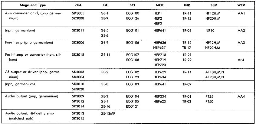
Table 1-1. General Replacement Transistors RCA Radio Corporation of America
INR International Rectifier GE General Electric Company SEM Semitronics
Corp.
SYL Sylvania WTV Workman Electronics Products, Inc.
MOT Motorola
Possible causes of distorted output are:
a. Defective neutralizing capacitor (see C55 and C59, Fig. 1-6).
b. Resistor greatly increased in value, such as R55 in Fig. 1-6.
c. Deteriorated detector diode (X6 in Fig. 1-6).
d. Failing transistor; measure terminal voltages.
e. Incorrect replacement transistor (see Table 1-1 for examples of standard rf, i-f, and audio types).
f. Fault in age system, such as open C6 in Fig. 1-6.
4. Incorrect Dial Indication In all superheterodyne receivers, the dial indication is determined by the local-oscillator frequency.
The reason for this is that most of the selectivity is provided by the IF amplifier. Since the incoming signal frequency is unchanged by the receiver tuning, and the IF amplifier responds to a fixed frequency, the signal can be passed only when the local oscillator is tuned to a frequency that produces the correct beat frequency. In turn, if the dial indication is in correct, either the local oscillator is at fault, or the dial assembly is defective in some manner that causes incorrect pointer location.
Possible causes of incorrect dial indication are as follows:
a. Dial-cord stringing incorrect, slack, or loose.
See receiver service data.
b. Dial plate incorrectly mounted or shifting in position.
c. Local oscillator incorrectly aligned. Check the tracking per receiver service data.
d. Defective capacitor in oscillator section.
e. Shorted turns or other defect in oscillator transformer.
f. Incorrect type of replacement transistor in oscillator circuit.
g. Incorrect type of replacement tuning capacitor.
Tracking is a technical term that denotes the ability of a receiver to maintain correct resonant frequencies in the rf, oscillator, and mixer circuits, at any point on the tuning dial. Dial-tracking refers to the ability of the system to indicate correct frequency values on the tuning dial when the receiver is in correct alignment. Therefore, we start by checking the alignment of the tuned circuits, as specified in the receiver service data. After the trimmers and slugs have been properly adjusted, we then turn to dial-tracking considerations, and any mechanical faults that might be involved.
5. Intermittent Operation
Whenever an intermittent "ties up" an AM tuner on the bench, the most useful approach is to monitor the operation of the various circuit sections for a suitable length of time. Specialized monitoring instruments can be employed, or conventional meters and scopes will serve the purpose. It is advisable to energize the tuner with a steady signal from an AM generator and to monitor the outputs at the RF amplifier, mixer, IF amplifier, and detector with VTVMs or scopes. In turn, when the intermittent occurs, informative data is provided without disturbing the circuits-next, the monitoring instruments can be connected at various points in the defective section, to close in on the defective component.
Possible causes of intermittent operation in an AM tuner are:
a. Local oscillator "drop-out" due to low supply voltage or a defective transistor.
b. Mechanical intermittent such as a poor connection; can often be localized by tapping.
c. Microscopic break in PC wiring; shows up clearly when the PC board is flexed slightly up and down.
d. Thermally intermittent resistor or transistor; localize by using a heat lamp, followed by a spray coolant.
e. Intermittent capacitor; monitoring procedures will pinpoint.
f. Marginal defect in tuned coil or transformer; tap with a tuning rod or pencil; press assembly gently from side to side; press terminals while observing output from the tuner.
g. Broken conductor inside an insulated lead; flex lead while monitoring.
h. Frayed insulation, permitting intermittent short circuit.
i. Plug not fully inserted into receptacle.
6. External Interference
External interference is sometimes due to "cockpit trouble"; that is, if the customer connects the AM tuner to an excessively high and long external antenna, it may be impossible to prevent powerful local stations "feeding through" when the receiver is tuned to a weak station. There is particular need for restricting the antenna signal level when no pre-selection is provided in an AM tuner. In any case, the experienced technician will determine the prevailing conditions in the given locality, and whether all the receivers in the area might be affected by external interference. Antenna trap circuits may need to be provided. When an interference complaint is legitimate, the trouble will usually be a result of poor alignment, or a component failure that disturbs alignment.
Possible causes of external interference in AM tuner operation are:
a. Previous sloppy alignment job; check alignment adjustments carefully per receiver service data.
b. Defective capacitor, such as C58 in Fig. 1-6.
c. Incorrect replacement loop antenna.
d. Defective RF or IF transformer; shows up as in ability to tune, or as an abnormally broad peak.
e. Incorrect replacement type of RF transformer.
f. Defect in agc section that causes tuner to operate at maximum gain regardless of the incoming signal level.
7. Poor Selectivity
Poor selectivity is generally due to the same defects or mis-adjustments that were noted under
Topic 6. In addition, poor selectivity sometimes is the result of a defective IC in systems such as shown in Fig. 1-3.
When a defect develops in an IC, we can usually con firm the suspicion by means of DC voltage measurements at the package terminals. This procedure is helpful in distinguishing between a defective IF transformer and a defective IC package.
8. Drifting Off Frequency
Off-frequency drift can occur in any section of an AM tuner; however, it is most common in the local oscillator section. The frequency of oscillation is affected by the condition of components other than coils and capacitors; for example, a deteriorating transistor can cause frequency drift. A leaky capacitor may cause frequency drift as the leakage resistance fluctuates. Bias variation on a transistor due to capacitor leakage or resistor instability often causes frequency drift. This is the result of the extremely high value of Q in an oscillatory feedback circuit.
Possible causes of off-frequency drift in an AM tuner are:
a. Leaky capacitor, such as C62 in Fig. 1-6.
b. Deteriorating oscillator transistor.
c. Unstable resistor--e.g., R32 in Fig. 1-6.
d. Marginal defect in oscillator coil.
e. Mechanical defect in tuning assembly.
f. Operation of tuner in poor location, such as a patio exposed to fog or mist.