Mechanical combination locks abound--as do ideas for electronic ones. Unfortunately, electronic designs we've seen are either too simple (and of limited use) or too complex --and beyond the average hobbyist. Here's something that's in between these two extremes.

DIGGING THROUGH THE files produced a wealth of ideas for locks--most of them impractical for the constraints imposed on the project application. Tossing ideas around the office threw up some fascinating techniques ... But we had to get a simple project together.
The simplest method is to connect several rotary switches in series to apply power to a solenoid-operated door lock when you dial up the right switch position on each. This has the advantage of extreme simplicity and a reasonable number of possible combinations. Problem is, if you leave that combination set on the switches then security is compromised because somebody, less trust worthy than your good self, may just take notice, Tch, tch.
What was needed was some technique that was self-cancelling or did not reveal the combination once it was 'dialed up.' It occurred to us that the rotary numerical combination lock, such as on safes (you know--spin the dial, 13 left, 37 right, 21 left), did not reveal the complete combination once the lock was opened.
Having digested that little principle the next thing was to work out how to do it electronically --and in a simple way.
The rotary numerical combination locks operate by successively unlatching a mechanical 'circuit'. When the last combination is dialed the bolt is released. How to do this electronically?
LATCHING CIRCUITS
A number of 'latches' connected in series and operated in sequence such that power is applied to a solenoid lock when the last latch is selected will be an electronic equivalent to the mechanical combination lock. Next problem --the electronic latch. This can be made up in a number of ways. Relays can be connected to latch on when energized. But they're relatively expensive. Digital logic gates can also be connected to make a latch.
When a silicon controlled rectifier (SCR) has a voltage applied to the gate it will conduct and remain 'on' until the anode-cathode voltage falls to zero. That's a latching operation. SCR's are cheap and readily available and will handle the current required to operate a solenoid lock and for these reasons were chosen for the latches in this project.
To dial a sequence of numbers, providing the required combination, we first considered a multi-bank, multi-position switch. That turned out to be mechanically awkward and expensive. Suitable switches are also difficult for the average hobbyist to obtain. Two, 12-position, single-pole rotary switches were eventually chosen. They are an 'off-the-shelf' item obtainable from many component outlets.
Dialing three pairs of numbers in sequence on the switches simulates the operation of a rotary numerical combination lock --almost. This provides over 1.7 million combinations! RESETTING That solves the combination problem and the latch problem, but how do you reset the SCRs once you've operated the lock? Simple --turn off the power source.
A switch could be used to momentarily disconnect the supply, 'unlatching' the SCRs, resetting the solenoid lock to await its next use.
What if you forget to push the button? Tch, tch, tsc ...
It seems a peculiarity of human nature that it is easy to memorize a sequence of numbers but very difficult to remember to reset a button or lock.
A simple timer operating a relay can do the job for you. Accordingly, the project has a timer incorporated.
The project is designed to operate from a battery. No current is drawn until the START button is operated.
Current will only be drawn from the supply for the 25 seconds duration of the timer.
Mains operation, from a small transformer and rectifier is possible but a battery standby circuit should be included in case of mains power failure.
SOLENOID LOCKS
There are two basic types. solenoid operated striker plates (i.e.. that are fixed in the door jamb) and solenoid operated bolts (attach to the door itself). We recommend you use a solenoid operated striker plate. Firstly, as they are fixed in the door jamb it is an easy matter to conceal all wiring. Secondly they may be used with existing dead-latching mortise locks. Solenoid operated bolt locks are made to fix on the door itself and require a flexible lead run across the door at the hinged side.
Solenoid operated striker plates or bolt locks are available from specialist locksmiths.
As the project operates from a 12 volt supply, a 12 volt version was used.
For new installations the key barrel of a lock may be dispensed with. In existing locks, the key mechanism may be disabled if you wish.
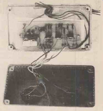
----------Interior of the lock. A diecast box provides a rugged and
safe housing.

--------This
shows how the connection of wires A to C and A' to C' determine the combination
of the lock. The above table shows the connection pattern for the combination
4-1, 1-11, 8-4 which can be seen by looking at the switch contact numbers
corresponding to A, A', B, B', C and C'. TABLE 1

------- Fig. 1 The circuit diagram, SW1, SW2 and PB 1 have to
be operated in the correct sequence before the lock will open. Any deviation
in sequence will result in the lock remaining secure.
---------------
How It Works
An 'initial' code is dialed on SW-1 and SW-2, 4 and 1 in this case. The gate of SCR1 will be forward biased via R5, SW-1, SW-2 and D2, SCR1 turns on, charging C2 to 12 volts.
The push-button PB1 is then pressed. This applies 12 volts from the cathode of SCR1 to the junction of R1/R2. Capacitor C1 will quickly charge to 12 V Q1 and Q2 will turn on, operating the relay RLA. The circuit involving Q1, Q2, R1, R2, C1 and the relay is a 25-second timer. The relay will drop out after about 25 seconds as C I will slowly discharge via RI, R2 and the input impedance of Q1, Q2, which is very high. The' rest of the sequence must be completed within 25 seconds to operate the lock for when RLA drops out, the circuit is 'reset'.
When PB1 is pressed and RLA operates, the relay contacts, RLA1, will then transfer the 12 V supply from the anode of SCR I to the anode of SCR2. SCR1 will turn off. C2 will then commence to discharge via R7, falling to a volt or so within 10 seconds. The next code sequence must be dialed within this period, otherwise you will have to return to the 'initial' code.
The second code is then dialed on SW-1 and SW-2, in this case 1 and 11. The gate of SCR-2 will then be forward biased via SW-1 and SW-2, the current it draws will discharge C2. SCR2 will then turn on, applying 12V to the anode of SCR3.
The third code is then dialed on SW-1 and SW-2, in this case 8 and 4. The gate of SCR3 will then be forward biased via R10, turning SCR3 on, energizing the solenoid lock. At the end of the 25-second delay, the relay will drop out, resetting the circuit.
An external connection socket, SK 1 is provided to enable power to be supplied to the lock should the circuit fail or the batteries run flat.
No current is drawn by the circuit until the operating sequence is commenced.
Diode DI suppresses operating transients from the coil of the relay and D2 prevents possible spurious triggering of SCR2 and SCR3 via the gate of SCR1 when the latter is turned on.
The circuit is protected from spurious triggering by bypass capacitors C3 and C8 and the SCR gate resistors, R6, R8 and R11.
-------

------ (top) The printed circuit board and solenoid striker plate we
used. Naturally any type of solenoid lock can be protected using this
system.
------ (above) A simple lock using three rotary switches. If you forget to move them off the combination after opening the lock, you'll reveal it.
----- (above right) PCB artwork shown full size.

Fig. 2 The component overlay. See Table 1 and the circuit diagram
for an explanation of the lettered AC pins. ----------
Parts List
RESISTORS
(ALL 1/4 W, 5%) R1 2M7 R2 470k R3 1k R4 100R R5 1M R6 100R R7 560R R8 1k R9 100R
CAPACITORS
C1, 2 10u 25V tantalum C3-8 1
On greencap
SEMICONDUCTORS
SCR1-3 C106Y1 or C106D1 Q1, 2 BC107, BC108, BC109 or BC 549 or equivalent D1 1N914 D2 1 N4007
MISCELLANEOUS
SW1, 2 1 pole 12 way rotary
PB1 miniature push to make
RLA1 single-pole change-over 1 2V 180 ohm coil, 240V/5A contacts
SKi DIN 5-pin or similar
Solenoid-operated lock (see text), 12V battery, pcb. diecast case.
----------------
CONSTRUCTION
The relay and all minor components are mounted on a printed circuit board. For convenience, and to avoid wiring errors, this method of construction is recommended.
Commence by putting all the resistors and capacitors on the board. Take note of the orientation of the tantalum capacitors. Next mount the transistors, diodes and SCRs --take note of lead orientation, carefully follow the component overlay diagram. Mount the relay last.
All external connections are made via pc pins inserted in the appropriate holes on the board. To avoid wiring errors, follow a sequence of wiring the connection from each pin, step by step.
Wiring a 'code" on the switches is a fairly simple process. Using the table below, allocate switch position pairs for SW1 and SW2 for each code in the three-step sequence necessary to open the lock.
For example, the code sequence of switch position pairs as shown in the diagram is 4-1, 1-1 1, 8-4. These are respectively shown connected to pc pins A-A', B-13", INSTALLATION
As this will very much depend on individual circum stances, we can only give you general guidelines.
Firstly, there must be no externally exposed, or visible, wiring. The switches should be mounted such that their shafts protrude from the surface behind which the circuitry is mounted, without the shaft securing nuts being accessible. File a flat on the shafts so that you have a permanent 'location' point for knob grub screws.
Better still, use collet knobs.
The external power/connection socket should be placed in a concealed location, known and accessible only to yourself, or those entrusted with the combination.
OPERATION
1. Dial the 'initial' code. As illustrated in the circuit, turn SW1 to 4 and SW2 to 1 .
2. Press the push button, PB1 .
3. Dial the second code. As illustrated, turn SW1 to 1 and SW2 to 1 1 . You have less than 10 seconds to do this.
4. Dial the third code. Turn SW1 to 8 and SW2 to 4, as illustrated.
5. The solenoid lock will release.
6. Twenty-five seconds after operating PB1, the circuit will reset and the lock will return to its latched condition.
---------------
Buylines
There should be no problems in obtaining any of the components used in the Combination Lock.
(adapted from: Hobby Electronics magazine, Sept. 1979)
Also see:
Thyristors: The Great Gate Story