Thyristors often seem to be the poor relation as far as electronic components go, especially these days with new digital ICs appearing almost daily. We would like to dispel/ any rumors here and now, the thyristor is alive and well, doing things that only they can do. Ian Sinclair looks at this versatile semi-conductor and a few of its unique features.
IF YOUR ELECTRONICS interests are in Hi-Fi, or short wave reception, chances are you'll never have any need to use a thyristor. There's an awful lot of other branches of electronics, though, in which these devices are extremely useful, so let's take a look at how the thyristor works, what it does, and the sort of circuits that are used.
Unlike the ordinary transistor, a thyristor has four layers of semi-conductor material (Fig. 1). Connections are made to the outer layers of this sandwich, and these are called the anode and the cathode connection. One of the middle layers is also connected to a terminal, called the gate.

Fig. 1. Four-layer arrangement (a) and the thyristor symbol (b).

Fig. 2. Two-transistor equivalent (a) as layers, (b) as separate transistors.
How does it work? Imagine the four layers split up as shown in Fig. 2a. This now looks like two transistors (Fig. 2b) connected in series one a PNP type, and the other NPN. More important, there are connections from the collector of the PNP to the base of the NPN, and from the collector of the NPN to the base of the PNP--that means 100% positive feedback. Using this transistor arrangement as a guide, let's see what we would expect to happen as voltages are applied. One thing has to be added though--the connection to the electrode which behaves like the gate has a bit of resistance in series (Fig. 3), and that makes quite a difference.
With the emitter of the PNP transistor positive and the emitter of the NPN negative, no current will flow when the gate" voltage is low. Since the "gate" connection is to the base of an NPN transistor, no current will start to flow until the voltage on the box is something like 0.5 V positive to the emitter of the NPN transistor. With the base of this transistor at the same voltage as the emitter', then, there's no conduction in either transistor. Either transistor? Well, you see, the collector of the NPN transistor will be at supply voltage when no current flows, and that keeps the PNP type shut off--a PNP transistor doesn't conduct until its base voltage is less than its emitter voltage. Fig. 3 shows a "load" resistor dotted; there's no resistor deliberately placed there but leakage through the semiconductor serves the same purpose.

Fig. 3. The equivalent circuit, with gate resistance added.
GATE RESISTANCE
When the base input voltage rises to around 0.5 V, then, the NPN transistor conducts, its collector voltage drops, making the PNP transistor conduct, and current flows from the emitter of the PNP transistor all the way to the emitter of the NPN one.
This is where the resistance at the "gate" input comes in. When the transistors conduct, the collector voltage of the PNP transistor goes high, keeping the base voltage of the NPN one high. If the input voltage goes low now, some of the current from the PNP transistor will flow through the input resistor, but the base of the NPN transistor will still be kept high enough to ensure that current keeps flowing. This is why the thyristor doesn't shut off. In fact, small thyristors can be shut off if the supply voltage is low by taking the gate voltage negative, so that the voltage at the base of the NPN transistor drops below 0.5 V.
PEAK CURRENT
There aren't two separate transistors, of course, so what do we look for when we select a thyristor? One obvious factor is the maximum voltage which we can use across the thyristor when it is switched off. This ranges from around 15 V to over 800 V according to the type that is chosen. Note, though, that these voltages are peak, so that if you want to use a thyristor with 240 V AC you need a 400 V type to hold off the peak AC voltage.
The next thing to look for is the peak current rating.
Many manufacturers quote I_Tsm--meaning the peak current flowing for a once-only pulse when the thyristor is triggered on. The repetitive peak current (on every cycle) is symbolized as ITRM, and is quite a bit less.
The gate trigger current, in milliamps, is labeled IGT and is usually measured at 25 deg C --it gets less at higher temperatures. The maximum value for reliable triggering is usually quoted, ranging from about 200 uA for a small thyristor to 30 mA or more for a large one. The actual trigger current is often a lot less--I have triggered a small thyristor at 8 uA.
VoT, as the letters suggest, means the gate voltage (maximum) which will ensure triggering. This ranges from 0.8 V for a small thyristor to 1.5 V for a large one --once again most samples will trigger at lower values.
Finally, the quantity IN is the holding current--at any greater value of current between anode and cathode, the thyristor is guaranteed to keep conducting once triggered. Values range from 5 mA to 40 mA, and, as usual, most samples will stay conducting with quite a bit less.

Fig. 4. A crowbar protection circuit.
The thyristor therefore behaves like a diode --but only when the voltage at the gate has set the layers of semiconductor conducting. With the gate connected, to the cathode, a thyristor is simply an open circuit, no current can flow in either direction unless, of course, the voltage ratings of the thyristor are exceeded. When the gate voltage is increased sufficiently above the cathode voltage--about 0.5 V or so--the thyristor will suddenly become conducting, provided the anode is positive relative to the cathode. In this state, the thyristor is said to be triggered. If the anode voltage is zero or negative, or if the gate voltage is too low, no triggering takes place, and the thyristor remains non-conducting.
Let's look now at a circuit which makes use of what we know already about the thyristor. Fig. 4 shows what is called a crowbar circuit--it's designed to shut off the power to a circuit very quickly.
This is a thyristor which is normally non-conducting, with its gate connected to zero volts through RI and to the positive supply through ZD1, a zener diode. You're not too certain about a zener diode? Well, it's a diode which is used reverse biased, but because of its construction it will suddenly conduct at some voltage, usually in the range 2.7 V to 33 V, which is decided when the diode is made. In this circuit, the diode has been selected so that it breaks down at 5.6 V.

Fig. 5. Burglar alarm basic circuit--the bell cannot be connected directly
to the thyristor because each stroke of a bell interrupts the current;
this would shut off the thyristor.
FAST FUSE
Now the normal voltage output of this circuit is 5.0 V, and it's intended to supply a lot of IC's whose supply voltage must not rise much above 5.6 V. What happens if the voltage does get too high? Simple --ZD 1 conducts and triggers the thyristor. The thyristor can then con duct, shorting out the power supply and causing the fuse to blow. Once the fuse has blown, there's no voltage in the circuit, and the thyristor instantly resets, ready to resume protection duty when the fault that caused the trouble is sorted out.
Now it may look a bit daft using a thyristor to blow a fuse, but it has two important advantages. The most obvious one is the fuses don't blow just because the voltage rises, so that the fuse doesn't protect the circuit against excessive voltage, it only protects the power supply against excessive current. The other point is that a fuse takes some time to blow, several milliseconds.
That may not sound like a long time, but several hundred pounds worth of IC's can be destroyed in only a thousandth of that time. The thyristor operates faster, getting the voltage down as soon as it reaches danger level, and blowing the fuse so that some attention is called for. The name-crowbar-circuit is a good one--the action is pretty much the same as that of putting a crowbar across the supply voltage!
To change output voltage, just switch in another zener diode! The output is not easy to smooth to an acceptable standard for most electronics equipment, but is ideal for battery charging or running lights or motors.
The main application for thyristors, however, is the control of lamps or motors, using the gate to control at what part of the wave the thyristor switches on. Fig. 10 shows how this operates when the supply to the thyristor is a full-wave rectified voltage. If the thyristor is turned on at the start of each wave, the output is at full power--the average value of voltage of such a wave is equal to 63% of peak voltage. If the thyristor is turned on at a later part of the wave, the average value of voltage of the output wave is less, down to nearly zero if the thyristor is switched on very late. This is, incidentally, one of two methods of control, the other will be discussed later.
TRIGGERING
The problem now is to trigger the thyristor at the correct part of each cycle. One simple method is to use a capacitor and resistor to delay the rise of voltage at the gate. Fig. 11 shows the simplest type of circuit possible, a capacitor connected across the gate, and a resistor feeding the capacitor from the rectifier supply. As the supply voltage rises from zero, following the shape of a half-wave of AC, the voltage across the capacitor will rise much more slowly, so that the gate voltage does not rise high enough to trigger the thyristor until the supply voltage is quite a bit above zero. We can alter the time (after the wave starts from zero) at which the thyristor fires by altering the time constant of the firing circuit.
Unless we discharge the capacitor again, however, the thyristor may fire too soon on the next wave, so that D1 is used to ensure that the capacitor discharges when the supply voltage drops at the end of the wave.

Fig. 11. Simple CR low voltage phase control. Because of the time that
C1 takes to charge, the voltage at the gate reaches trigger level some time
after the input voltage starts to rise.
The delay can be adjusted by altering the setting of RV1. D1 discharge C1 when the input voltage drops to zero again.
One snag of this simple circuit is that the current passing through the charging resistor may not be enough to fire the thyristor, if the resistor is a large value and the thyristor gate needs a large (1 mA or so) current.
Most small thyristors will fire with a gate current of a few uA, but the larger types may need quite a bit more.
A method of overcoming this is the trigger diode --a device which is non-conducting until a few volts are applied between anode and cathode (Fig. 12), and which then becomes fully conducting, with only a small voltage drop. Using such a trigger diode, the voltage across the capacitor (Fig. 11) builds up until the voltage across D2 is enough to breakdown the trigger diode.

Fig. 12. Trigger diode. (A) symbol (b) characteristic

Fig. 13. Using a transistor for triggering a low-voltage circuit.
LOW VOLTAGE
With the diode fully conducting, the voltage at the gate is more than enough to trigger the thyristor, and gate current is provided by discharging C1 rather than by the small current through R1.
A version of this basic circuit suitable for low voltage supplies is illustrated in Fig. 13. A transistor takes the place of the trigger diode making use of the principle that a transistor will pass a large current from collector to emitter when a small current passes from base to emitter. The capacitor C1 is connected to the base of Q1, so that base current will start to flow when the capacitor has charged to about 0.5 V. The base current causes collector current, so that the emitter voltage rises along with the base voltage. When the emitter voltage rises to about 0.5 V (the base will by this time be at about 1.0 V), the thyristor fires.

Fig. 14. Using an AC load and a bridge rectifier circuit. The thyristor
circuits of Figs. 11 or 13 can be used if the voltage is low.

Fig. 15. Mains-voltage power control. All parts of the circuit can be at
a dangerous voltage.
If the load is AC operated (such as a shaded-pole motor, for example) the circuits used so far do not appear useful because they are based on rectified AC. However, the circuit is still a circuit, whether a rectifier is used or not, and the load can just as easily be connected in the AC part of the circuit (Fig. 14). In this example, the firing of the thyristor completes the circuit, so switching the current on. The change of position of the load from the DC to the AC side of the circuit does not alter the action of the thyristor.
So far, all the circuits we have looked at have been low voltage circuits, for which ordinary low voltage components and construction methods are suitable.
Many thyristor and triac control circuits, however, make use of AC mains voltages, for which a number of special precautions need to be observed. One essential point is electrical safety. In a mains circuit, the thyristor is.
connected between the load and one of the mains leads, usually neutral. Since the gate must have a fairly low resistance to the cathode, this means that all the electrodes of the thyristor are connected to mains, and any firing circuit of the simple type will also be connected to the mains.
Great care must therefore be taken when these mains voltage circuits are isolated from any low voltage circuits and that no mains voltage points can be touched. In the simple power control circuit of Fig. 15, for example, widely used for electric drill or light bulb control, the potentiometer control knob must be well insulated--one useful method is to use a potentiometer with a plastic shaft, with the circuit fitted into a plastic box.
Particular care has to be taken when a heat-sink is needed for the thyristor because the insulators which serve well for mounting power transistors to heat sinks are not good enough for mains voltages. A mains-operated thyristor should never use a metal box as a heat sink --if cooling is needed, the thyristor should be mounted on a finned heatsink mounted on substantial insulators inside a ventilated box.

Fig. 16. Isolating the firing circuit from the thyristor. (a) Using a pulse
transformer. (b) Using an optoisolator. With either device, the insulation
between the circuits can be good enough to withstand several thousand volts.
ISOLATION
Several applications of mains-voltage thyristors and triacs involve driving the gate with signals from low voltage equipment --typical applications include disco lights. There are two safe ways of isolating the thyristors from the low voltage equipment--pulse transformers.
Now applications for thyristors such as the crowbar circuit are very useful, but they represent only a fraction of the possible uses. Fig. 5 shows in outline, for example, how a thyristor could be used in a burglar alarm circuit--the point is that the bell will keep on ringing once the thyristor has been triggered, until the power is cut off. Some care is needed, incidentally, in the uses of this circuit. Small thyristors need very little gate current to trigger them, around 1 uA, so that a long lead attached to the gate of a thyristor will pick-up any electrical disturbance (next door washing machine, for example) unless a resistor is connected between gate and cathode. Once again, we are making use of the thyristor as a device which can be switched on by a small and brief change of voltage, but which cannot be switched off the same way. Anything that behaves in this way is called a latching device. Now we can connect up relays so that they will latch, but a thyristor is self-latching--this type of behavior is built in to the thyristor.
NEGATIVE PULSE
Suppose we want the thyristor to stop conducting? it happens, some small thyristors will switch off when the gate voltage is pulsed negative, but this is not a reliable way of switching off. Switching off, as far as most thyristors are concerned must be done by reducing the voltage between anode and cathode to a very low value. Once this minimum value, the minimum holding voltage, has been reached, current stops. Unless the gate voltage is kept high, the current will not start to flow again when the anode returns to a positive voltage.

Fig. 6. Simple low-voltage light-switch circuit.
One obvious way to do this, of course, is to interrupt the supply momentarily, as shown in the low voltage lamp circuit of Fig. 6. A less simple method consists of discharging a capacitor at the anode of the thyristor, as shown in Fig. 7. In this circuit, the thyristor is triggered by the action of the push button switch--note the 1-k resistor (R2) which prevents the gate from being triggered by stray radiated pulses. Once the thyristor has been triggered on, there is a low-resistance conducting path between anode and cathode, so that the voltage across the thyristor is low, not much above the minimum holding voltage at which the thyristor switches off.
The switch-off method uses a large-value capacitor C1 which charges up when the thyristor conducts. During the time that the thyristor conducts, the capacitor has one plate at supply voltage and the other at the low voltage of the thyristor anode. When the OFF switch is momentarily depressed, the plate of the capacitor which was at supply voltage is suddenly connected to Zero volts. The other plate will follow it, dropping from about 0.2 V to a negative voltage for a few milliseconds. This is time enough to allow the electrons and holes in the N and P layers of the thyristor to clear and the thyristor becomes non-conducting. By the time the capacitor has re-charged through the load, the thyristor is off.

Fig. 7. Using a capacitor to switch off a thyristor.
Fig. 8. A two-thyristor switching circuit. The capacitor C1 is connected so that when one thyristor switches on, the other is forced off.
BACK TO BACK
This method works well when the load has a fairly high resistance (such as a low voltage lamp) and when a large value capacitance can be used. The capacitor should be a paper or plastic type, because electrolytics do not take too well to having their plates at reverse polarity, which will happen if the OFF switch is kept closed while the capacitor re-charges through the load. A variation of this method uses two thyristors switching each other (Fig. 8).
Thyristors really come into their own, however, when they can be used with a supply which passes through zero volts at regular intervals. An alternating voltage fits this specification nicely, but a rectified unsmoothed supply is even better. The reason is that a thyristor will pass current in one direction only, so that to cope with AC we need two thyristors, or the ready-made two thyristor device known as the Triac.
Using an unsmoothed rectified supply ensures that the thyristor will turn off each time the voltage reaches zero (or a fraction of a volt above zero). We don't need any special switch-off circuit, but on the other hand we have lost that rather useful latching action. To keep the thyristor conducting we must either keep a current flowing into the gate, or apply a pulse each time the anode voltage starts to rise.
Fig. 9. A simple voltage regulating circuit. If this is used as a better
charger (for lead-acid batteries only), C2 can be omitted.
A very simple circuit making use of this principle is shown in Fig. 9. This is a voltage adjuster; which enables you to obtain several switched values of DC voltage from a transformer without using toppings. It's particularly useful for lead-acid (car or motorbike) battery charging, as the voltage is so easy to charge. The principle is that the zener diode, which may be one of several selected by a switch, applies a steady voltage, equal to the zener diode voltage, to the gate of the thyristor. At the anode of the thyristor, the waveform is a full-wave-wave rectified wave from the bridge rectifier.
The cathode of the thyristor is connected to the reservoir capacitor C2, a large value electrolytic rated at the full peak voltage of the transformer secondary.
To see what happens, imagine that the peak voltage of the rectified wave is 25 V and that we have a 1 5 V zener diode. When the circuit is first switched on, capacitor C2 is uncharged, so that the cathode voltage of THI is zero. When the voltage at the anode starts to rise, the thyristor will not conduct right away, because C1 has to be charged up first. As C1 charges, however, TH1 will switch on, so that current flows, charging C2 to the full peak voltage.

Fig. 10. Phase control of a wave. The average voltage at the output depends
on how late in the cycle the thyristor is triggered.
LOADING
Now if there is no load resistor connected across C2, the thyristor will not conduct again even if it is triggered because the anode voltage will not be any higher than the cathode voltage. Any normal power supply is used with a load, however, so that we can assume that the voltage across C2 will drop quite a bit between the time of the first voltage peak and the next one. If the voltage across C2 is higher than the zener diode voltage, though, the thyristor will not trigger, and the next voltage pulse does not cause the thyristor to conduct.
This continues until the output voltage drops to less than the voltage of the zener diode. When this happens, the thyristor will start to conduct whenever the anode voltage is higher than the cathode voltage, and the reservoir capacitor C2 will once again be charged to the full peak voltage. The thyristor will conduct every now and again; enough to keep the average voltage at the output fairly steady at around the zener diode voltage, and opto-isolators, illustrated in Fig. 16. Pulse transformers can be obtained which have insulation guaranteed to 4 kV, but which will fire even a large thyristor when a pulse is applied to the primary. Opto-isolation provide smaller output powers, but can be used to trigger a small thyristor which then fires the main thyristor. Great care must always be taken with disco light equipment, because faulty insulation in such equipment is responsible for an increasing yearly total of deaths caused by electrocution.
The other type of problem which is encountered when thyristors are used with mains voltages is that of radio frequency interference (RFI). When a thyristor switches on suddenly at or near the peak of a wave, a large pulse of current flows, and the steep-sided wave is very rich in harmonics. Such a wave is radiated easily from all the wiring around the thyristor, and interferes badly with radio, particularly on the lower frequencies. The long wave radio-4 transmissions, in particular are badly affected by thyristors in TV receivers, in light dimmers, drill speed controllers and other thyristor power circuits.

Fig. 17. Reducing radio-frequency interference (RFI).
Complete elimination of RFI is difficult, but a considerable reduction in interference is possible if RF chokes and filter capacitors are fitted into the circuit (Fig. 1 7).
These generally consist of inductors constructed with several turns of insulated wire (typically about 40 turns) on a ferrite rod, with 0.01 uF capacitors to earth on each side of the inductor.
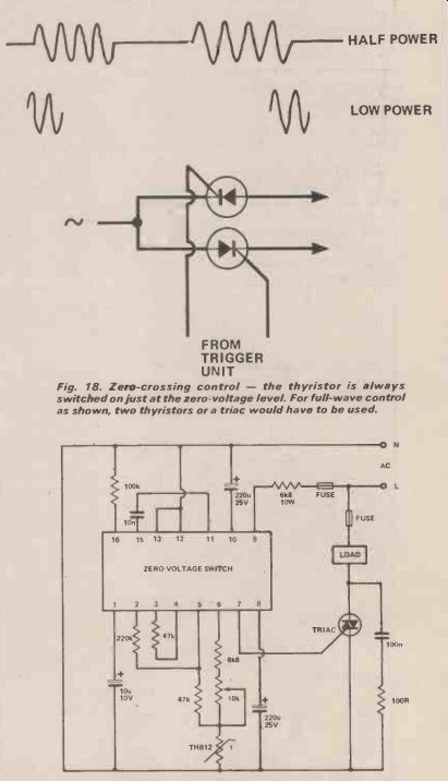
Fig. 18. Zero-crossing control--the thyristor is always switched on just
at the zero-voltage level. For full-wave control as shown, two thyristors
or a triac would have to be used.
Fig. 19. A zero-crossing switch circuit used for temperature control. Note that all points can be live. (Courtesy of RS Components Ltd).
ZERO VOLTAGE CROSSING
A different approach to the problem of interference, and to thyristor control, is the zero voltage crossing control system. This can be used only when the load has a lot of energy storage, such as a large heater, because the idea is to switch the thyristor on when the wave is at zero volts, to keep the thyristor on for several cycles, and then to keep the thyristor off for another few cycles. In this way (Fig. 18) the power can be controlled by varying the ratio of the number of "on" cycles to the number of-off-cycles. Obviously, this is useless for loads such as lights or drill motors, but for loads such as heaters which do not charge noticeably when power is removed for several cycles this method has a number of advantages.
For one thing, since there are no sudden switch-on pulses, greater amounts of power can be switched.
Because the switching occurs at the zero crossing points of the wave, there is no RFI. The only penalty is a more complex circuit due to the need to generate a pulse when the wave passes through zero, and to time a number of cycles on and another number off. Fortunately, integrated circuit zero-voltage crossing controllers can be obtained from Feranti and from Plessey among other manufacturers. Fig. 19 shows the circuitry used with a zero-crossing type of circuit controlling a triac. In general, triacs are used on purely AC circuits, with thyristors being used on DC or rectified AC supplies.
When very large amounts of power are to be controlled, thyristor bridges can be used when no triac of suitable power rating is available.
(adapted from: Hobby Electronics magazine, Sept. 1979)
Also see: