| Home | Audio mag. | Stereo Review mag. | High Fidelity mag. | AE/AA mag. |
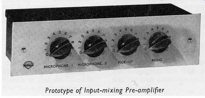
It may often be desirable to use several signal sources with an amplifying unit which has provision for only one input signal. The circuit described in this section is capable of handling four input signals and of supplying a mixed output voltage suitable for driving a single-input amplifier. Two of the input channels of the mixer are suitable for microphone signals, a third for a radio or equalized-tape input and a fourth for crystal pick-up signals.
The circuit as it stands provides an output voltage of 40mV and was intended to be used with the version of the 10W amplifier in which the tone-control network is disconnected, described in Section 6.
With a simple modification to the output stage, the mixer will provide an output voltage of up to 800mV.
CIRCUIT DESCRIPTION
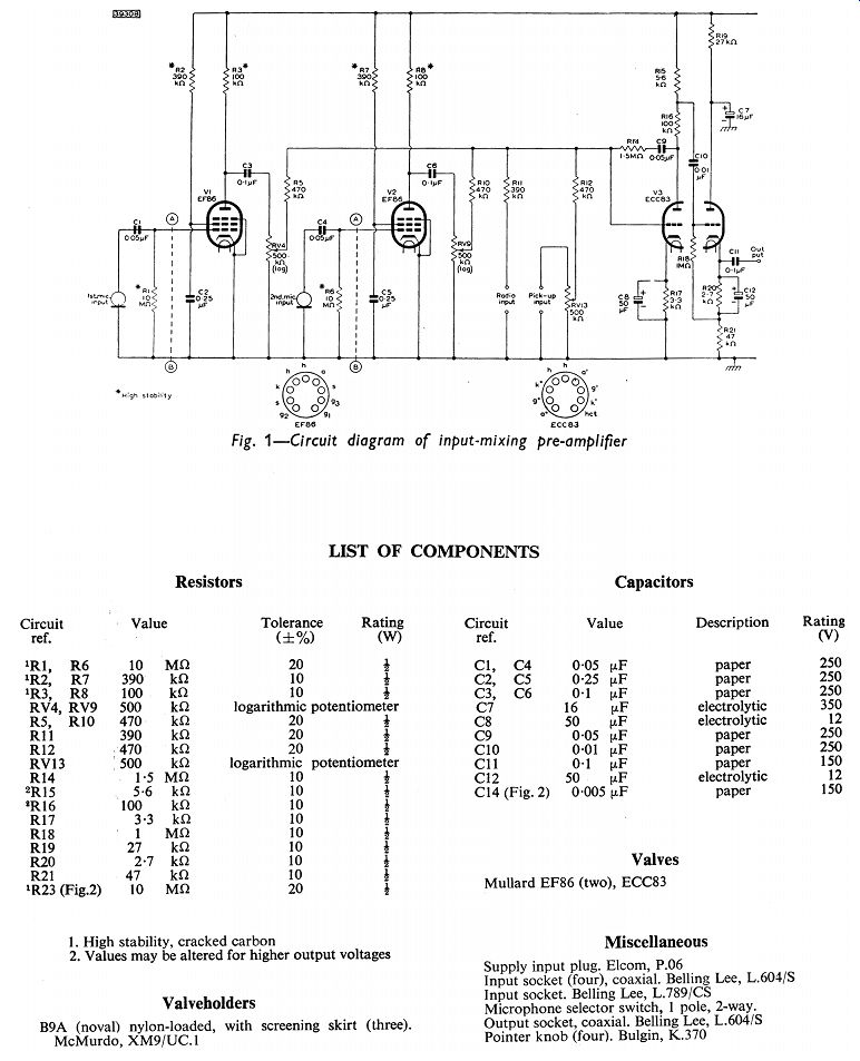
Both microphone input stages of the input mixing circuit are identical. Each is equipped with the Mullard low-noise pentode, type EF86, operating with grid-current bias obtained by means of the high-value grid resistor R1.
The internal impedance of a crystal microphone is predominantly capacitive, and the capacitance is of the order of 2000pF. Therefore, to avoid loss in terminal voltage at low audio frequencies, the microphone should be connected to a high-impedance input stage. If a low value of resistance of 1.5 M-O is chosen for R1, for example, the combination of the series capacitive elements of the microphone, the grid-circuit capacitance C1 and the grid resistance R1 will result in a loss of about one-third of the output voltage from the microphone at a frequency of 100Hz. Consequently, a value of 10M-O has been selected for R1 to provide the high-impedance input for the crystal microphone and to prevent the loss of bass output voltage.
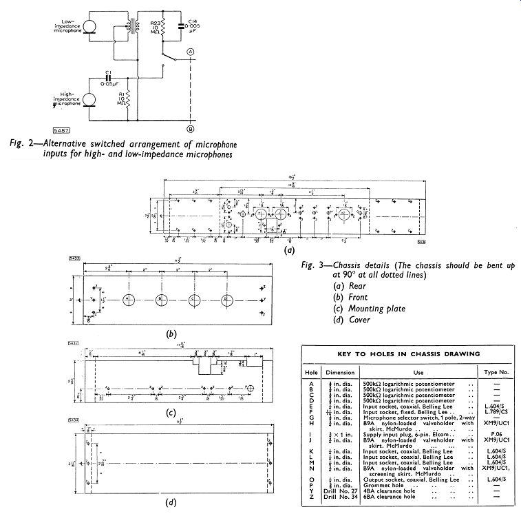
If it is required to use a low-impedance microphone such as a moving-coil or ribbon type, the mixer can be made suitable by using a step-up transformer in the grid circuit of either EF86. A switched arrangement for low- and high-impedance microphones is shown in Fig. 2. The connections marked A and B in Fig. 2 should replace those similarly marked in Fig. 1. The output leads of the microphone transformer should be made as short as possible to avoid hum pick-up and loss in treble response.
The output from each microphone input stage is RC coupled to the grid of one half of the Mullard high-µ double triode, type ECC83.
The radio and pick-up input stages are also connected to this grid by way of the resistors R11 and R12, RV13. This half of the ECC83 is arranged as a voltage-amplifying stage.
-----------
The potentiometers RV4, RV9 and RV13 serve for the adjustment of signal level and the mixing of the microphone and pick-up input channels. Adjustment for the fourth channel will be achieved by means of the gain control incorporated in the radio unit used at the radio input terminals. (If it is required, control of the radio input can be achieved by connecting a potentiometer to the radio input socket in the way that RV13 is joined to the pick-up socket.)
The values of the resistors R5, R10, R11 and R12 have been chosen so that, in combination with the potentiometers RV4, RV9 and RV13, they reduce any interaction between the channels considerably. These fixed resistors also ensure that the grid of the ECC83 will not be short-circuited when any one of the potentiometers is set at a minimum.
The output stage of the mixer unit is suitable as it is shown in Fig. 1 for use with the control-less version of the 10W amplifier. The circuit has been arranged so that the sensitivity at the microphone inputs is 3mV for an output voltage of 40mV, and this is sufficient for crystal microphones. The sensitivities of the other input stages, for the same output voltage, are 230mV and 250mV for the radio and pick-up terminals respectively.
-----------
Feedback is taken from the anode to the grid of the first half of the ECC83 by way of the components R14 and C9. The purpose of this is to provide a low -impedance at the grid and hence minimize the loss in response at treble frequencies caused by Miller effect between the anode and the grid of the triode.
The output voltage is obtained from the second half of the ECC83 which has been connected as a cathode follower. This type of connection provides a low output impedance which, in Fig. 1, has the approximate value of 600?. Because of this low impedance, little, if any, attenuation of high notes will occur as a result of cable capacitance if a long cable is required between the mixer unit and the main amplifier. The input impedance of the main amplifier must be
-------------
-----------
------------- Tbl 1, 2 greater than 100k-oto ensure that the bass frequencies will not be attenuated by the coupling capacitor C11.
The h.t. current taken by the mixer circuit is 5mA at 190V. The value of the smoothing resistor depends on the power amplifier used, and appropriate values are given in Table 1. The l.t. current drawn by the unit is 0.7A at 6.3V.
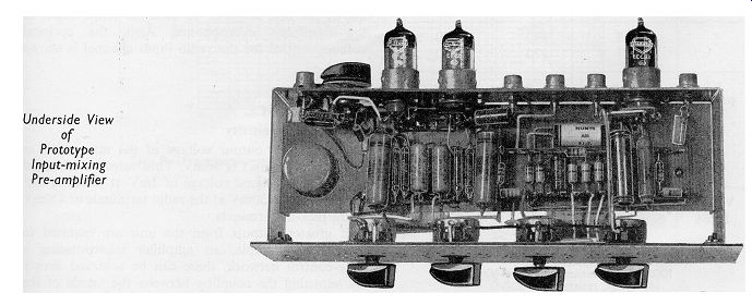
CONSTRUCTION AND ASSEMBLY
Chassis details of the input-mixing pre-amplifier are given in Fig. 3.
Space has been left in the chassis for the transformer (Fig. 2)
necessary for converting the high-impedance microphone input into one suitable for low-impedance microphones. Space has also been provided for the optional volume control for the radio input channel.
The chassis is made up of five separate pieces of 16 s.w.g. aluminum sheet. The dimensions (in inches) of these pieces are as follows:
(a) Front panel 11 1/2 X 3
(b) Rear panel 18 1/2 x 2 1/2
(c) Mounting strip 11 11/16 x 2 5/8
(d) Cover plate (two) 11 1/2 x 3 11/16
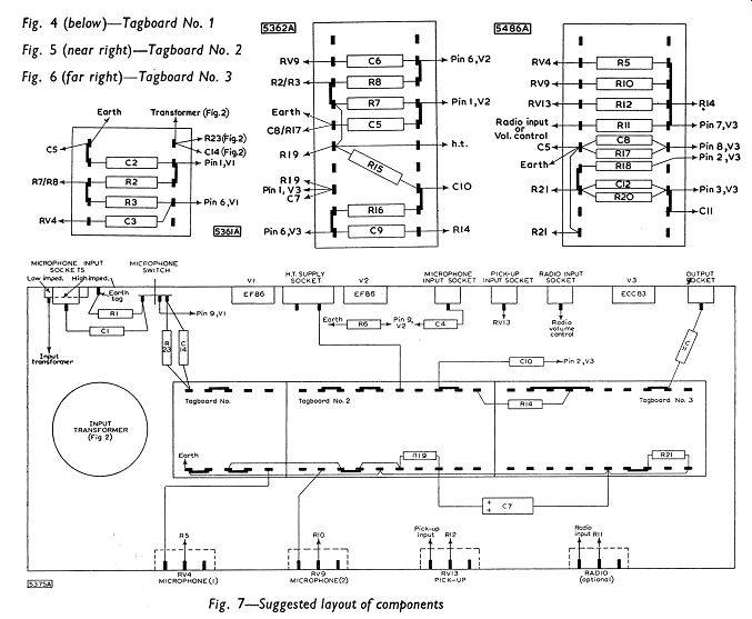
A suggested layout for the components of the four-channel pre-amplifier is given in Fig. 7. The arrangement of the components on the tagboard is shown in Figs. 4, 5 and 6. The first stage of the pre-amplifier has been modified in this layout to incorporate the facilities for low-impedance microphones. The transformer is included, and a switching arrangement allows the first stage to be used for either high- or low-impedance microphones. Also, the optional volume control for the radio input channel is shown in Fig. 7.
PERFORMANCE
Output and Sensitivity
The maximum output voltage of the mixer unit as it is drawn in Fig. l is 40mV. This output is obtained with an input signal voltage of 3mV at either microphone socket, 230mV at the radio terminals or 250mV at the pick-up terminals.
If greater outputs from the unit are required to drive, for example, an amplifier incorporating a tone-control network, these can be achieved simply by adjusting the coupling between the anode of the first triode of the ECC83 and the grid of the second. If the capacitor C10 is joined directly to the anode of the first triode, an output of 800mV will be available. Intermediate values of output voltage can be achieved by altering the values of R15 and R16. If, for example, R15 and R16 were each 47k-o, the output voltage of the unit would be about 400mV.
If the required output voltage from Fig. 1 had been obtained by attenuating the output voltage from the cathode load in the final stage, the low output impedance resulting from the cathode-follower action would have been lost.
Frequency Response
The response curve of the mixer unit, measured between the microphone socket and the output terminals is shown in Fig. 8. The curve is flat to within +3dB, relative to the response level at 1KHz, from 20Hz to 20KHz. The response curve measured between either the radio or the pick-up socket and the output terminals is shown also in Fig. 8. Because the EF86 stages are not included for this second position of measurement, the bass response is slightly extended and the curve is flat to within ±2dB, compared with the 1 KHz level, from 15Hz to 20KHz.
Hum and Noise
Measurements of hum and noise were made with 100k-oresistors connected across the microphone and pickup terminals and with the potentiometers fully advanced. These arrangements simulate a reasonable practical condition. The mixer was connected to a 10W amplifier and measurements were made across a 15-ohm load resistor.
The voltage measured in this way was 38mV.
The full output of the amplifier is 10W which corresponds to a voltage. of 12.3V across the 15 -ohm load resistor. Consequently the hum and noise level is 50dB below 10W. The background level of the power amplifier alone is better than 70dB below 10W, so the figure of 50dB must be attributed to hum and noise in the mixer unit.
D.C. CONDITIONS
The d.c. voltages at points in the equipment should be tested with reference to Table 2. The results shown in this table were obtained with an Avometer No. 8.
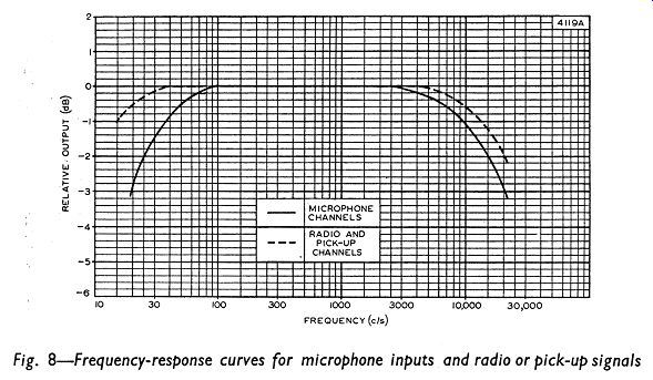
Fig. 8
--------