| Home | Audio mag. | Stereo Review mag. | High Fidelity mag. | AE/AA mag. |
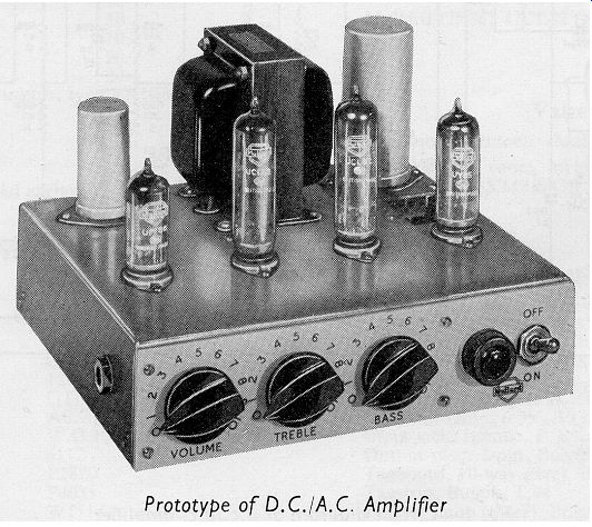
The circuit described in, this section is intended primarily for those who require high-quality audio reproduction but who are limited to, or are likely to encounter, d.c. mains supplies. The amplifier can be arranged to accommodate any speaker impedance without the need for rewiring if an output transformer having a tapped secondary winding is fitted. The absence of a mains transformer means that the unit is much smaller than other amplifiers of comparable output power.
The equipment operates in the range of mains voltage (a.c. or d.c.) of from 200 to 250V, and the maximum output power available is between 7 and 8W at low distortion. Negative feedback of 21dB is used to improve the performance of the complete amplifier, but even with this high value of feedback, the sensitivity of the circuit is high enough (200mV) to allow its use with most types of crystal pick-up head or with FM radio tuner units.
Four Mullard B9A (noval) valve (tube) s - types UF86, UCL82 (two) and UY85 - are used in the amplifier. The heaters of these valve (tube) s (rated at 100mA) are connected in a series chain. Because of this and the high a.c. voltages appearing at some of the heaters when the unit is operating on a.c. mains, the standard of performance in respect of hum pick-up is necessarily a little below that to be attained with equipment such as the 10 or 20W amplifier. But the performance is still very good and, as satisfactory results have been obtained with a variety of makes of crystal pick-up head, the d.c./a.c. amplifier should satisfy most of the demands for equipment of this nature.
------------
CIRCUIT DESCRIPTION
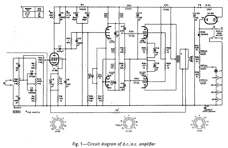
The circuit diagram for the d.c./a.c. amplifier is given in Fig. 1.
The input stage of the amplifier incorporates the Mullard high-gain, low-noise pentode, type UF86, used as a voltage amplifier. In the second stage of the equipment, the triode sections of two triode-pentodes, type UCL82, form a phase-splitter. This provides the drive for the pentode sections of the two UCL82 which operate as a self-biased, push-pull output stage with a nominal anode-to-cathode voltage of 200V.
Negative voltage feedback is used to improve the performance of the complete amplifier. It decreases distortion, improves the frequency response and reduces the output resistance.
The power supply of the amplifier uses the Mullard half-wave rectifier, type UY85. The rectifier output is RC smoothed, and the anodes of the push-pull pentodes are fed from the reservoir capacitor C20 through the center-tapped primary winding of the output transformer.
Tone-control Circuit
The passive network comprising the tone-control circuit in this equipment is identical with that of the 10W amplifier described in Section 6. It will provide all the control necessary for normal usage.
Pick-up of hum voltages in the tone-control network is minimized by enclosing all the control components in a metal screening box. This box is isolated from the chassis by a sheet of paxolin and is held at the negative h.t. potential. The cases and spindles of the potentiometers are connected to this screening box. The chassis should not be connected to an earth point.
Details of the tone control are given in the circuit diagram in Fig. 1.
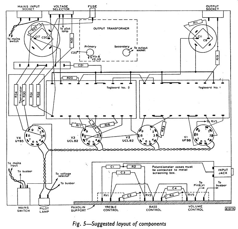
The treble and bass controls are RV1 and RV3 respectively. RV5 is the volume control. The arrangement of the components within the metal screening box is given in Fig. 5.
Input Stage
The UF86 in the first stage of the amplifier is connected to the neutral end of the series heater chain. In this way, there is a minimum transfer of hum voltage from the heater to the control grid of the valve (tube) . To obtain a low level of noise in the amplifier, high-stability components should be used for the resistors R6, R7 and R9 in the anode, cathode and screen-grid circuits of the UF86.
Instability in the amplifier can result from the large amount of negative feedback introduced into the cathode circuit of the UF86. It can also occur because of the impedance that exists between the chassis and the busbar which serves as the negative return line of the amplifier. The following precautions are taken to prevent any possibility of instability.
The simplest method is to reduce the loop gain of the amplifier. To do this at high audio frequencies, the capacitor C6 is connected to bypass the anode load resistor R6. To reduce the loop gain at bass frequencies, the parallel combination of R10 and C10 is included in the coupling circuit between the first and second stages of the equipment. This method of coupling results in resistive attenuation at the low audio frequencies, so that the phase shift is limited. In addition, the busbar is connected to the chassis by way of the capacitor C21.
Phase-splitting Stage
The triode sections of the two UCL82 form an anode-follower phase-splitting stage. Such an arrangement has been chosen because of the large amount of negative feedback that occurs between the anode and grid of V3A. This can be used to counteract the large hum voltages transferred, with an a.c. mains supply, to the grid of V3A as a result of running the heater of V3 some 62V above the neutral voltage level.
The balance between the output voltages from the triodes of this stage is controlled by the values chosen for the resistors R14, R16 and R17.
If resistors which deviate from the nominal values by the extreme of the 5 % tolerance range are used for R16 and R17, the resulting lack of balance should not be more than 4 %.
Output Stage
The pentode sections of the UCL82 are used in a push-pull output stage. Normal pentode loading is used so that maximum output power is obtained with any h.t. voltage. The valve (tube) s operate under the following class AB conditions:
Anode-to-cathode voltage 200V
Screen-to-cathode voltage 200V
Cathode circuit resistance (each pentode) 390 ohm
Anode-to-anode load 6k-o
Quiescent anode current 2x35mA
Rectifier Stage
The resistor R34 is included in the cathode circuit of the UY85 to limit surge currents through the valve (tube) . The fuse FS, rated at 150mA, is also included in the h.t. circuit.
Heater Circuit
The heaters of the four valve (tube) s used in the amplifier are connected in series. The UF86 in the input stage (which has the highest gain) is connected to the neutral side of the mains supply.
The nominal drop in voltage across the four heaters in series is 150V. The difference between this and a mains voltage in the range 200 to 250V is taken up by the following components connected in the heater circuit: the Varite thermistor R30 (type VA1010) used for surge suppression; the resistors R31 (470 ohm), R32 (120 ohm) and R33 (120 ohm) used to provide tapping points for the ranges of mains voltage; the pilot lamp LP used as an indicator. The components R30, R31 and R32 are mounted under a ventilation hole cut in the chassis.
This allows dissipation of the heat developed in these resistors.
Negative Feedback
The amount of feedback taken from the secondary winding of the transformer to the cathode circuit of the UF86, is 21dB. The output resistance with this feedback is 0.9?, measured at the 15? output terminals. This gives an adequate damping factor of about 17.
Fig. 1
CONSTRUCTION AND ASSEMBLY
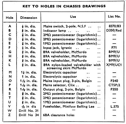
Chassis details for the d.c./a.c. amplifier are given in Fig. 2. The two metal pieces of the chassis should be cut from 16 s.w.g. aluminum sheet and the insulator from paxolin sheet, 1 /16in. thick. The dimensions (in inches) of these pieces are:
Main chassis 12 x 11 Screening box 6 3/8 x 4 7/8 Insulator 5 5/8 x 1 7/8
The arrangements of the components on the tag-boards is given in Figs. 3 and 4 and a suggested layout of the components in the chassis is shown in Fig. 5.
In all d.c./a.c. equipment, certain precautions must be taken to prevent constructors and users receiving electrical shocks. This possibility of shocks arises because the amplifier can inadvertently be connected wrongly to the mains supply. If the polarity of the mains connection is incorrect, several components will become ‘live'.
In this amplifier, the chassis is insulated electrically from the internal components and wiring except for a single connection, by way of C21, between the chassis and the busbar return line of the amplifier.
(This connection is required for reasons of stability.)
The amplifier itself should be contained in a well-ventilated insulating box. If this is not possible then at least the ventilation hole and the electrolytic capacitors on the top of the chassis must be protected to prevent people touching them. The potentiometers should be fitted with knobs which prevent any contact with the bare spindles and which have no protruding grub screws.
To prevent hum pick-up, there are no isolating capacitors in the input circuit. For this reason great care must be taken when connecting auxiliary equipment to the amplifier. It is essential that no exposed metal parts are connected to either side of the input circuit of the amplifier. Earth connections in associated equipment should be dispensed with, as there is a risk that one side of the mains may become connected to them. They are also likely to cause hum trouble.
It should also be borne in mind that the speaker leads are connected to the busbar, and because of an incorrect mains connection this may become ‘live'. Thus the metal parts of the loudspeaker should be inaccessible.
----
PERFORMANCE
The performance data given in this section have been obtained from measurements made on a prototype amplifier using a typical output transformer. Except for the relationship between output power and mains voltage, all the data have been obtained with an a.c. mains voltage of 240V. The measurements have been made with a sine-wave input signal.
Output Power
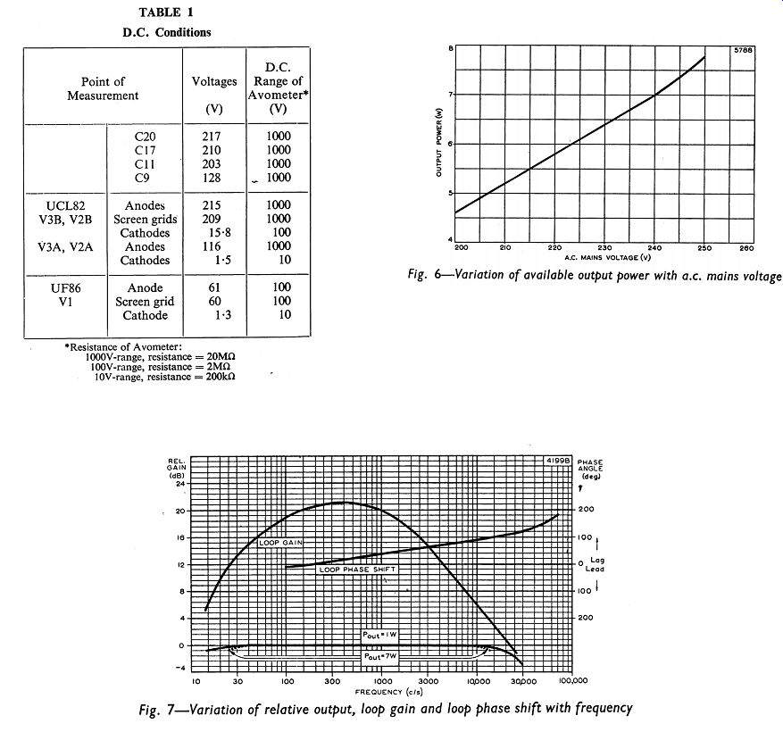
The variation of obtainable output power with mains voltage is shown in Fig. 6. It can be seen that the rated output of 7W at an input frequency of 1- khz is obtainable with an a.c. mains voltage of 240V.
The maximum output for a mains voltage of 250V is 8W. When a d.c. mains supply is used, the output power will be lower because less h.t. voltage will be available.
Distortion
The total harmonic distortion, measured at 400Hz, is about 0.5 % for an output of 7W. For an output of 3W, the distortion is 0.2 %.
Intermodulation distortion was measured at 40Hz and l0KHz, the amplitude of the low-frequency signal being four times that of the high-frequency signal. At an equivalent output power of 7W, the intermodulation distortion is 2 %. At an equivalent power of 3W, the…
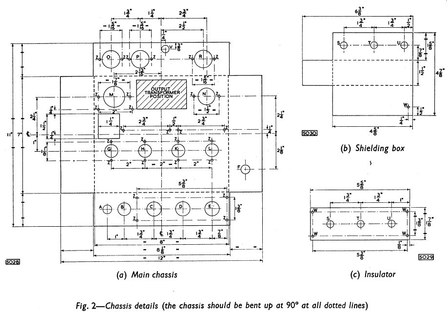
Fig. 2
…distortion is 1 %. The stipulated equivalent output power is the power that would be obtained from a single sine-wave input of amplitude equal to the peak value of the combined low- and high-frequency inputs. The distortion is expressed in r.m.s. terms as the percentage of the intermodulation products relative to the higher frequency.
The magnitude of the beat-note distortion was found to be negligible in the prototype amplifier.
-----------
Frequency Response and Stability
The frequency-response, loop-gain and phase-shift characteristics for the prototype amplifier are given in Fig. 7.
At the full rated output of 7W, the response curve is flat to within ±1dB (relative to the output level at 1- khz) for frequencies ranging from 15Hz to 14KHz.
The phase shift in the feedback loop is only 117° at a frequency of 22KHz when the loop gain is unity. Consequently, the amplifier has a stability margin at high frequencies of 63°. The phase-shift characteristic below 100Hz is not given in Fig. 7. Nevertheless, adequate stability at low frequencies has been achieved in the amplifier.
Tone Controls
The treble tone-control potentiometer RV1 gives continuously variable control from +10dB to -10dB at 10KHz, and the bass potentiometer RV3 gives such control from +8dB to -5dB at 100Hz.
Sensitivity
The input voltage required for the amplifier (including the tone-control network) to give the rated output of 7W is 200mV. This is enough to allow its use with most types of crystal pick-up head or FM tuner unit.
-----------------
------------------
Fig. 5
Hum and Noise
In several copies of the prototype used with a.c. mains supplies, the hum and noise level, with the volume control set to zero, was always better than 60dB below 7W. This is not as good as the level normally achieved with present-day high-quality audio equipment. But the level is still very satisfactory, and can be considered good if the limitations set by the series heater chain and the associated high alternating potentials with a.c. mains operation are borne in mind.
D.C. CONDITIONS
The d.c. voltages at points in the equipment should be tested with reference to Table 1. The results shown in this table were obtained using an Avometer No. 8.
-----------
---------- Fig. 6-7