The name electron-coupled oscillator (ECO) is derived from the way the oscillation in the plate tank circuit is supported or replenished by fluctuations in the electrons streaming through the tube. Upon reflection we will realize that the name electron coupling does not describe something unique to this circuit, since the oscillation in any plate tank circuit is likewise replenished by fluctuations in the electron stream.
Figs. 1 and 2 show the operation of the electron-coupled oscillator for each half-cycle. Inspection of the circuit will reveal a Hartley-type oscillator between the grid and cathode. Since the Hartley oscillator was covered in detail in Section 3, its mode of operation will be reviewed only briefly here. The necessary components of an electron-coupled oscillator include:
C1-Grid tank capacitor.
L1-Grid tank inductor (used as an autotransformer).
R1-Grid-leak bias resistor.
C2-Grid coupling capacitor.
V1-Tetrode vacuum tube.
C3-Screen-grid bypass or filter capacitor.
R2-Variable resistor used for adjusting the screen-grid bias voltage.
C4-Plate tank capacitor.
L2-Plate tank inductor.
M1-Power-supply or other voltage source.
These components form convenient combinations:
C1 and L1 form a tuned oscillatory circuit.
C2 and R1 form a conventional RC filter with a long time constant.
C3 and the upper part of R2 form another long time-constant RC filter.
C4 and L2 form a second tuned oscillatory circuit.
The currents at work in this circuit include:
1. Grid tank current ( dotted blue).
2. Feedback current (dotted green).
3. Plate and screen-grid currents (solid red).
4. Grid-leak bias current (solid green).
5. Screen-grid "biasing" current (dotted red), which might also be considered a voltage-divider current.
6. Plate-tank oscillating current (solid blue).
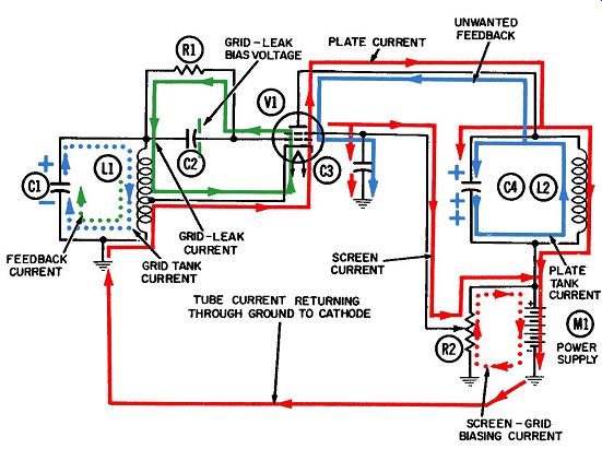
Fig. 1. Operation of the electron-coupled oscillator-positive half-cycle.
The grid tank current (dotted blue line in Figs. 1 and 2), oscillates between
the upper and lower plates of capacitor C1 through inductor L1, alternately
driving the grid negative and positive. To keep the tank current oscillating,
it is periodically replenished or strengthened by the feedback current (dotted
green line). The latter in turn is driven by the plate current through the
lower portion of inductor L1.
Fig. 1 depicts the positive half-cycle of operation. Grid tank electrons are amassed on the lower plate of capacitor C1, making the upper plate positive--and also the control grid, since it is coupled to the top of the tank through capacitor C2. A pulse of plate current is released through the tube and arrives at the top of the tuned tank (L2-C4) at the moment its voltage is least positive (depicted by the single plus sign on the upper plate of C4 in Fig. 1). Being composed of negative electrons, the plate current pulse lowers the already low positive voltage and thereby replenishes the oscillation in the plate tank.
Some of the current exits from the tube at the screen grid and flows through the upper portion of potentiometer R2, through the power supply to ground, and back to the cathode.
Another current leaves the tube at the control grid in the form of grid-leak current, shown by the solid green lines. This occurs only once each cycle, when the control-grid voltage becomes momentarily positive. Because of the high resistance of grid resistor R1, these electrons cannot immediately return to the cathode, but will accumulate on the right plate of grid capacitor C2, building up the negative grid-leak bias voltage. Through out the entire cycle, there has been a slow and continuing drain of electrons back to the cathode, through the grid resistor and the upper portion of L1.
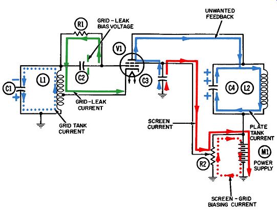
Fig. 2. Operation
of the electron-coupled oscillator-negative half-cycle.
As with plate and screen currents, a closed path back to the cathode must be available. Otherwise, enough electrons will accumulate on the grid capacitor and on the grid itself that the flow of tube current will be cut off entirely (known as "grid blocking") . Fig. 1 also shows a feedback current (dotted green line)
flowing in the grid tank. This current is produced by the auto transformer action of the inductor. (For a fuller treatment of the phase relationships between the grid-tank, plate, and feed back currents, refer to the Section on the Hartley oscillator.) This electron-coupled oscillator is a special tuned-plate-tuned grid configuration. Its distinguishing feature is that the grid and plate oscillations are isolated from each other by the screen grid.
Hence, there can be no feedback from plate to grid. An unwanted feedback current (solid blue line in Figs. 1 and 2) flows from the top of the plate tank and back to the plate, where it is coupled into the screen-grid circuit by interelectrode capacitance. In the screen circuit we see it being bypassed harmlessly to ground through capacitor C3.
There is nothing mysterious about this coupling from plate to screen by means of interelectrode capacitance, nor about the bypassing the feedback to ground. The same electrical principle is employed for both-namely, the natural ability of a capacitor (including two objects having a capacitance toward each other) to pass an alternating current. Fig. 1 shows a half-cycle of this unwanted feedback current flowing from the plate tank to the plate, from the screen grid to the upper plate of capacitor C3, and finally from the lower plate of C3 to ground. In the negative half-cycle of operation of Fig. 2, these directions are reversed.
You may wonder why feedback from the plate tank is unwanted in this circuit; in others such as the crystal or TPTG, the continuance of the oscillation depends directly on feedback between the output (plate) and input (grid) circuits. Obviously, the reason is the Hartley oscillator in the grid circuit. As explained in Section 3, it needs no feedback from the plate, since it generates its own between the cathode and grid circuits.
One of the virtues of an electron-coupled oscillator circuit is its frequency stability, made possible by the isolation between the load circuit (plate tank) and the basic oscillation in the grid tank.
The oscillating current in the plate tank is generated for the sole purpose of getting it to perform some useful function. But in order to do so, it must first be coupled out of this circuit and into another one. One way is by transformer coupling between L2 and another inductor (not shown). Another is to connect the coupling circuit directly to the normal output point at the top junction of C4 and L2. Whichever means is used, it is inevitable that a new current will flow in the coupling circuit. Driven by the current/voltage combination in the plate tank, it will have the same frequency as, and its strength will be proportional to, the plate tank oscillation driving it. Thus, it constitutes a load on the plate tank oscillation and both weakens and detunes it. The detuning can perhaps be better visualized by considering the frequency formula: f= 1/2 pi LC and then recognizing that the proximity of additional coupling components-whether they be capacitors, inductors, resistors, or any combination-will change the effective values of L and C, and consequently the frequency.
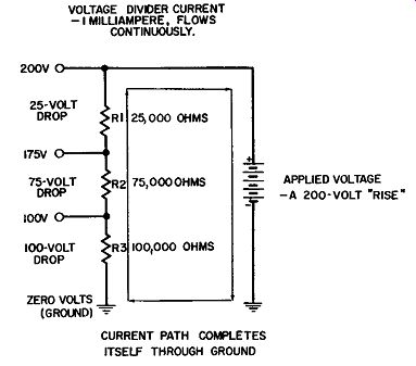
Fig. 3. A simple
voltage-divider network.
The purpose of the screen grid and its bypass capacitor is to shunt the feedback current harmlessly to ground before it reaches the grid. The strength and frequency of the feedback will vary with changes occurring in the plate tank oscillation as a result of loading. Hence, if allowed to reach the grid circuit, such feed back will change the basic oscillator frequency being generated in the grid tank. A pentode tube is often used in place of the tetrode shown in Figs. 1 and 2. Because its plate current is relatively unaffected by variations in plate voltage, a pentode will make a significant contribution to the amplitude stability of the plate tank oscillation. In simpler terms, any variation in coupling or loading between the plate tank circuit and the next stage or circuit may modify the strength of the oscillation, and accordingly, the strength of the voltage peaks at the top of the tank. However, these variations in plate voltage will cause no significant change in the plate current coming through a pentode. It is true that an unvarying plate current cannot correct existing deviations in amplitude or strength-but at least it will not be the source of new ones. In this respect, the pentode has the advantage over the less stable tetrode. If the tetrode of Figs. 1 and 2 is re placed by a pentode, all other currents will remain relatively unchanged. The screen-grid biasing current ( dotted red line) deserves special mention. Driven by the power-supply voltage, this current flows from the negative terminal of the power supply (the ground or neutral point, in other words), upward through potentiometer R2, and back into the positive terminal of the power supply. As a result of this current, a voltage is developed across R2 and a partial voltage exists at any point along this resistor, the amount depending on the distance between the two segments on each side of the contact point. Calculation of the voltage at any point is a straight Ohm's-law problem. When a potentiometer is connected across a voltage source as is done here, this combination becomes a special form of voltage divider. Resistor R2 might be considered as being made up of five or even ten smaller resistors, all connected in series across a voltage source. Each resistor serves to divide the available voltage into smaller ones which will always add up to the applied voltage. This is the meaning of Kirchhoff's law that all voltage drops and all voltage increases around a closed circuit must add up to zero. (Watch those polarity signs!) The following paragraph makes the meaning a little clearer. In interpreting Kirchhoff's law, an applied voltage is considered a voltage increase and given a positive sign, whereas voltages developed across resistive loads are considered drops and given an opposite, or negative, sign. Thus, when a certain number of positive units are added to an equal number of negative units, the sum is zero of course. Fig. 3 shows a sample voltage-divider circuit closely resembling the one used in the screen circuit of Figs. 1 and 2. Three resistances in series-- R1, R2, and R3--have replaced the potentiometer. Their values are 25,000, 75,000, and 100,000 ohms, so the series resistance of the combination is 200,000 ohms. With an applied voltage of 200 volts, we can calculate the current flowing in this closed circuit by using Ohm's law, as follows:
E I= R 200volts 200,000 ohms = .001 ampere = 1 milliampere.
Since this same current flows through each resistance, the voltage developed-or dropped-across each resistor can also be calculated from Ohm's law.
Call the voltage across R1 E1 : E1=ffi = .001 ampere X 25,000 ohms =25 volts.
Call the voltage across R2 E2 : E2 = .001 ampere X 75,000 ohms = 75volts.
Call the voltage across R3 E3 : Ea= .001 ampere X 100,000 ohms = 100volts. Note that the sum of these voltage drops is 200 volts, the amount of voltage rise represented by the power supply.
Voltage dividers are widely used in electronic circuitry for obtaining an infinite variety of partial voltages from a single source such as a power supply. They are usually the essence of simplicity. Paradoxically, they can be quite difficult to recognize on a schematic, particularly for someone with an untrained eye. First of all, they are rarely labeled voltage dividers. Also, the resistors frequently are widely separated from each other and from the applied voltage, often by a full page of the schematic.
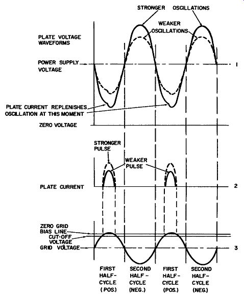
Fig. 4. Grid and plate waveforms in the electron coupled oscillator. It
is evident from Fig. 1 that the same positive voltage that exists at the
tap on the potentiometer will be applied to the screen grid. It is also evident
that the screen-grid current must flow through the upper portion of R2 in order
to reach the power supply. The voltage at R2 will be altered somewhat when
this happens. It is possible, by adjusting the tap, to compensate for variations
in amplitude of the plate tank oscillation ( caused by corresponding variations
in the loading or coupling current from circuits which come after the plate
circuit). This self-compensation enables the tetrode to exhibit some of the
amplitude stability previously attributed to the pentode. Now let us consider
an example.
Fig. 4 shows one cycle of plate voltage for an electron-coupled oscillator. (The plate voltage is the same as the oscillating voltage in the plate tank.) The positive half-cycle of Fig. 4 corresponds to the current/voltage conditions depicted in Fig. 1. That is, the grid voltage (line 3 of Fig. 4) reaches its most positive voltage in the middle of the half-cycle, releasing a pulse of plate current (solid curve in line 2 of Fig. 4). The current arrives at the top of the plate tank when the latter is least positive (solid curve of line 1 of Fig. 4) and thereby reinforces the oscillation.
The negative hump in the middle of the first half-cycle of plate voltage (solid curve of line 1) represents the addition of plate current electrons to the voltage across the plate tank capacitor.
Arriving as they do during this half-cycle, the electrons increase this voltage and thereby reinforce the oscillation.
Continuing with our example, assume this plate tank oscillation is weakened by, say, a variation in the load current being driven by the tank current. Also assume the dotted curve in line 1 now represents the voltage waveform at the plate and at the top of the tank. Since the oscillation has been weakened, the plate voltage at the center of the first half-cycle will not swing to as low a positive value as before. So now a larger pulse of plate current can be drawn across the tube. This condition, depicted by the dotted curve of line 2 in Fig. 4, stems from the fact that the plate voltage of a tetrode (unlike the pentode) does affect the plate current somewhat.
As the plate current increases, more and more electrons flow through the positively charged screen grid on their way to the plate. Thus, more and more electrons are captured by the screen grid and flow through the upper portion of R2, increasing the voltage drop across the top of the potentiometer.
Subtracting this greater voltage drop from the power-supply voltage, we end up with a lower positive voltage than before at the potentiometer tap and consequently at the screen grid. The lower screen-grid voltage now weakens the plate-current pulse which had originally lowered the screen voltage. So, a form of self-compensation exists.
These cumulative actions do not necessarily correct the amplitude variation already in the plate oscillation, but they do keep the plate current from following the changes in loading. In this sense they contribute to the over-all stability of the circuit including the frequency stability of the oscillation in the grid circuit, because any change in the plate current drawn by the tube will also change the strength of the feedback in the cathode to-grid tuned circuit. As is true for any tuned-circuit oscillator, any such variations in the feedback, or in loading, coupling, etc., will raise or lower the basic frequency.