THE endeavors of hi-fi enthusiasts, designers and manufacturers of hi-fi equipment have resulted in a single-channel, or monaural, reproducing system of extremely high standard. Harmonic distortion has been cut to less than I percent, the frequency response has been extended well beyond the audible range as a means of improving the transient performance, while the dynamic range and power-handling capabilities of modem hi-fi equipment leave little to be desired. Nevertheless, there is something lacking! With a monaural system, the sound which is picked up by the microphone in a concert hall, for example, represents a sample of the sound pressure which exists solely at the position of the microphone, and this sound eventually arrives at the two ears of the listener at the reproducing end by way of the loudspeaker. In other words, there is a complete, single channel between the sound source and the listener, and this is so irrespective of whether the connection between the microphone and the loudspeaker consists of a radio link, directly-connected cables or a recording system of some kind.
The idea is illustrated in Fig. 10.1.
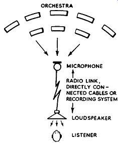
FIG. 10.1. The monaural system of sound reproduction.
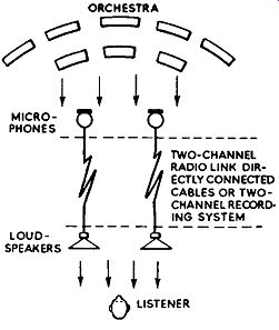
FIG. 10.2. The stereophonic system of sound reproduction.
This arrangement does not fit in with things as they are in reality, for at a concert performance the sound from the various instruments embraces a wide area in front of the listener and, even without the use of his eyes, he finds no difficulty in establishing the position of the instrumentalists. The reason for this is that both , ears collect the sounds coming from the orchestra various angles. The brain compares several factors of the sounds ... picked up by the two ears, and from the information thus abstracted brings into operation a form of sound location sense. Apart from the relative intensity of the sounds, this sound location function is dependent also upon the relative phase of the sounds at the two ears. It will be appreciated that there is a time difference between the sounds, and this may or may not be the same thing as a phase difference; the former term, however, applies essentially to sounds of a random and transient nature, while the latter applies to repetitive sound waves.
Sounds originating at the extreme right and left of a listener are dealt with by the right and left ears respectively, while sounds originating between these two points have their positions fixed (so far as the brain is concerned) by one ear picking up more sound than the other and by comparison of phase. It will be clear from this that a single-channel system cannot promote operation of the sound location sense, and that as a result of this the illusion of "perspective" and "spaciousness" of an orchestra is lost.
The problem is not solved by the use of two or more microphones connected in series or parallel at the studio end and two or more loudspeakers similarly connected at the reproducing end, since the individual signals, though they may differ in phase and amplitude, lose their separate identity in the single-channel network. With such a system, the sound simply appears to come from the loudspeaker nearest to the listener or from the loudspeaker which is radiating the greatest volume of sound; true perspective is not given because all the loudspeakers reproduce in proportion the same sound. Two or more loudspeakers in a single-channel system can help considerably, however, in spreading the sound over a large area, provided that due attention is given to their phasing.
THE BINAURAL SYSTEM
Correction of the loss of spaciousness and perspective is possible by the use of two isolated channels, as shown in Fig. 10.2. The greater the number of channels, the better the stereophonic effect, but economic considerations limit the number of channels for domestic use to two (the cinema industry is able to afford multi-channel systems). Fig. 10.2 shows that, in effect, the listener's two ears have been extended into the studio or concert hall where they are represented by microphones. Because the differences in the character of the sound picked up by the microphones are conveyed to the loudspeakers, the sound-location sense of the listener is brought into action, and he is given the impression of the spaciousness and perspective of the orchestra as if he were actually in the concert hall.
Consider a two-channel system with the microphones placed about 6 ft. apart, in front of which are placed about six people in line. If the loudspeakers are similarly placed in the listening room with regard to separation and channel, and the people in line at the front of the microphones are instructed to clap their hands in turn, starting with, say, the person nearest the right hand microphone, the listener at the loudspeakers will obtain the impression of the sound starting at the right-hand loudspeaker, moving across between the loudspeakers and finishing at the left-hand loudspeaker.
This is a stereophonic trick which can be used with great success in demonstrating stereophonic sound reproduction; usually, however, some thing more elaborate than hand-clapping is featured--an express train rushing through a station, a game of table tennis or something which illustrates vivid movement. The sound source will appear to be in the center between the two loudspeakers when the outputs are balanced. An announcer standing in the center between the two microphones would give this effect.
If he moved towards the left-hand microphone the sound would increase from the left-hand loudspeaker and decrease from the right-hand one; the converse effect would occur if he moved towards the other microphone.
This impression of movement, coupled with phase-comparison of the sound from the loudspeakers, produces a two-channel stereophonic effect of remarkably high standard. The illusion is somewhat enhanced by the reverberant sounds also being put into their correct perspective, so that they do not appear to come from exactly the same place as the original sound, as is the case with a single-channel system.
Once stereophony has been experienced, it is extremely difficult to settle down again to single-channel listening--a big attribute of stereophony is the marked reduction in listening fatigue. The placing of the loudspeakers, their phasing and the balance of sound are important factors which have to be considered with the greatest care if the best results are to be secured.
MICROPHONE PLACING
The use of fairly widely spaced microphones, as shown in Fig. 10.2, is not always to be recommended. This is because the space between the two loudspeakers may not be adequately balanced in relation to the level of sound from them. The sound may appear to be concentrated either side of the listener, with a distinct weakness in the center. This may prove distressing when the sound source is situated approximately in the center between the two microphones, since then the sound may appear to jump from one loudspeaker to the other at the listening end, particularly if the sound source happens to be someone moving about.
One method of overcoming this effect, developed by Philips, made use of an artificial head with microphones instead of ears. The masking effect of the head was relied upon to provide the amplitude and phase differences of the sound signals passed over the two channels. This scheme provides a stereophonic illusion at the higher frequencies only, since the masking given by the head reduces in efficiency as the frequency is decreased and as the wavelength of the sound becomes comparable with the head dimensions.
A system which is in current operation by E.M.I. for the production of their "Stereosonic" tape records calls for the microphones to be situated as close together as possible, one above the other. Use is made of pressure gradient microphones orientated so that their directions of maximum pick-up are at right-angles, and positioned in relation to the center of the sound source so that the maximum pick-up axis of each microphone falls at an angle of 45 deg.
Another scheme which has received some attention both in America and Great Britain is the placing of two microphones, one above the other, over the orchestra. The lower microphone is arranged to respond to the direct sounds, while the upper one is shielded from the direct sounds, but responds to reverberant and indirect sounds. It has been claimed that this method enhances the "presence" and atmosphere of an orchestral reproduction.
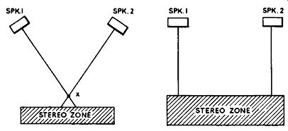
(Left) FIG. 10.3. This method of loudspeaker positioning has much to
commend it. (Right) FIG. 10.4. Another form of loudspeaker set up.
LOUDSPEAKER PLACING
The subject of loudspeaker positioning is a cont1oversial one, and also rather a problem if the most desirable listening position technically is not to conflict with day-to-day household functions.
The arrangement shown in Fig. 10.3 has much to commend it, even though the area of stereophonic effect may be somewhat limited. The point of optimum effect is shown at X, but movement from this ideal position disturbs the balance of sound and gives the impression of movement of the sound source. Within the stereo zone one can walk around without unduly disturbing the effect of balance. This is because if one moves from, say, the center of the stereo zone to the left the resulting increase in distance from loudspeaker 2 is offset by moving into its beam of greater sound level, while the decrease in distance from loudspeaker 1 is corrected by moving away from its beam of greater sound level. This effect was investigated in some detail by G.E.C. engineers during the course of their experiments in stereo phony. (G.E.C. gave its first public demonstration of stereophonic sound reproduction at the National Radio Show in 1951, magnetic tape being the recording medium used at that time.) The precedence effect also has some bearing on the balance and apparent location of the sound source, relating sound intensity with relative time of arrival of the sound at the two ears. For example, if the same sound is radiated from two sources, the brain senses that the sound comes from the source whose sound reaches the ears first. However, this effect can be balanced by increasing the intensity of the delayed sound accordingly.
The set-up shown in Fig. 10.4 also serves reasonably well, particularly in smaller rooms. Reflections from walls and furniture also disturb the stereo balance when listening under domestic conditions. In order to combat this trouble it is often necessary to experiment with the placing of the loud speakers, and best results may be secured with the loudspeakers arranged in some odd pattern which appears to have no theoretical validity. There should be no obstructions between the loudspeakers and the listener, however, and in order to satisfy this condition it sometimes helps to mount the loud speakers above the level of the furniture.
LOUDSPEAKERS FOR STEREO
Experiments have been carried out with several makes of loudspeaker and enclosure in different combinations, and in all cases the stereophonic effect was secured once the sound levels were correctly balanced. In one test a small battery portable receiver tuned to the BBC Home Service served as the left-hand channel and a table television receiver as the right-hand channel in connection with the BBC's stereophonic experiments. The effect was truly astounding; the inherent distortion of the non-hi-fi receivers appeared to disappear, and the reproduction resulting from the two unmatched loud speakers was definitely of hi-fi quality.
This would appear to bear out the opinions of other workers in the field: in fact, it has been suggested that a two-channel stereo system with a response good to 6 k hz sounds better than a single-channel system with a response extended to 15 k hz. However, the best results are undoubtedly gained by the use of two hi-fi channels with matched loudspeakers and amplifiers. The stereo effect is most marked in the middle and higher range of frequencies, and at these frequencies it is desirable for the loudspeakers to have omni directional characteristics. Ralph West ("Hi-Fi Year Book", 1958) suggests the use of reflecting cones serving as high-frequency diffusers, with the loud speaker enclosure preferably lying on its back. This idea has been tried, and works admirably.
Loudspeaker phasing is not as critical in the author's opinion as is made out by some authorities. Anti-phase conditions undoubtedly result in a loss of heavy bass, as would be expected, but the overall stereo effect is not severely affected, though there is a slight unevenness of the movement of the virtual sound source between the loudspeakers. Ralph West says "out-of-phase usually produces three sources-ahead, and one at each loudspeaker". What can be most disconcerting is unbalance of hum levels from the loudspeakers. During the course of recording the BBC's stereo experiments by way of V.H.F.-F.M. channels, one channel suffered badly from modulation hum due to the close proximity of e.h.t. cables. On playback (the stereo was recorded remarkably well) the hum appeared to be removed from the actual program material and to exist close to one ear of the listener, that nearest the humming loudspeaker.
EQUIPMENT REQUIRED FOR STEREO
In order to create the stereo effect in the home it is necessary to employ two completely separate hi-fi systems. Starting from the listener and working backwards towards the signal source, we require two loudspeaker systems, two power amplifiers to drive them and two pre-amplifiers or control units to feed the power amplifiers. Then there is the most important component--the two separate signals representative of the program material.
For use in the home, the program signals will be derived from either tape or disk records, and it will be shown later how the two signals are maintained separately on a single length of tape and on a common groove of a disk record. It is also possible to utilize two radio channels, one to carry the right-hand signal and the other to carry the left-hand signal. This method has been used on several occasions by the BBC in their experimental stereo phonic broadcasts. The television sound transmitters as well as the medium wave and V.H.F.-F.M. transmitters have been used on these tests in various combinations so as to allow the maximum number of listeners to participate.
It is not the intention of the BBC to make a permanent feature of stereophonic broadcasts at the present time, but radio-derived stereophonic sound is available to listeners in New York by switching on both radio and television receivers at the same time.
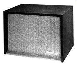
Fig. 10.5. Pamphonic Model S1 loudspeaker, specially designed/or use
in pairs with the Pamphonic stereo amplifier Model 3,000.
With regard to loudspeakers for stereophonic applications, we have already seen that these need not be accurately matched, or even of the same type, to secure good-quality stereophony. Obviously, the better the loudspeaker systems, the better the quality of reproduction, but since difficulty may be experienced in the housing of two large reflex enclosures in an average living-room, it is likely that miniature reflex enclosures suitable for table mounting or small console versions will become popular as stereophonic systems become more widely used, and several manufacturers are concentrating along this line. Fig. 10.5 shows the Pamphonic Model S1 stereo loudspeaker, which uses a concentric cone unit which is adequately loaded by the cabinet, and is specially designed for use in pairs with the Pamphonic Model 3,000 stereo amplifier.
Dual-channel, or stereophonic, amplifiers complete are now available, and these represent an ideal choice for the enthusiast just entering the field of hi-fi. Those already in possession of a single-channel hi-fi system are catered for, however, as stereo control units are also available for handling the two program signals, derived from radio, tape or disk, and passing them on to two (preferably matched) power amplifiers.
STEREO FROM DISK
There have been several attempts at producing stereo disk records, but the system which is now in use dates back to A. D. Blumlein's experiments around 1929, when a scheme for the simultaneous recording of two separate sound tracks in a common groove was evolved. The idea was patented in 1931, but at that time it did not represent a commercial proposition and was shelved. It was not until 1957 that the scheme was again brought to the notice of the public: it was demonstrated at the London Audio Fair and the B.S.R.A. exhibition by A. R. Sugden and in America by London Records (a Decca associate) and Westrex. Its re-introduction coincided with the growing interest in stereo reproduction, fostered by stereo tape records, and the advanced state of development of the gramophone industry as a whole.
The system of stereophonic disk recording as first expounded by Blumlein and now in current use requires only a single recording stylus and recording head to produce recordings of both stereo channels in a common groove, and a single pick-up with only one stylus to reproduce both channels of the recording.
It will be remembered that a disk record can be made in two ways: the conventional method whereby the modulation is imparted due to the recording stylus oscillating to-and-fro in sympathy with the applied modulation, and the hill-and-dale process whereby the modulation affects the depth of the cut and the groove remains straight with no side-to-side curves. Basically, stereo records are produced by combining both of these methods, so that one channel modulates the groove laterally, as with an ordinary record, and the other channel modulates the same groove vertically.
The stereo recording head is therefore arranged to have two electromagnetic systems so that when energized by the applied signal one causes the recording stylus to move laterally, while the other causes it to move vertically; the movement of the stylus is thus in two planes, and corresponds to the complex modulation pattern of the two stereo channels.
Similarly, the pick-up has two generating systems which respond individually to the vertical undulations and the lateral displacement of the recorded groove. The voltages generated by the two systems correspond to the signals in the two channels and, since the pick-up is so designed that there is very little interaction between the two systems, connection can be made direct to the appropriate amplifiers in the usual manner.
The patents of A. D. Blumlein allowed not only for the lateral-vertical system of recording two channels in a common groove, but also for an arrangement known as the 45/45 system. Whilst the modulation is imparted into the groove by a slightly different method to that already described, the 45/45 system gives almost comparable results. With due attention given to the phasing of the two electromagnetic systems in the recording head and of the generating systems in the pick-up, either system can be used for recording or reproduction on the same type of equipment. With the 45/45 system, which is the one adopted, the two stereo channels are recorded at an angle of 45 deg. to the surface of the disk, and each channel is cut towards the opposite wall of the groove, thus producing a single complex groove.
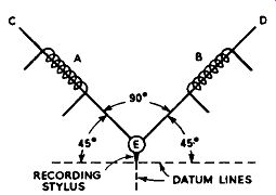
FIG.10.6. Simplified diagram of the essential elements of an electromagnetic
stereo recording head.Let us investigate how a stereo record is cut,
so as to secure a better understanding of the 45/45 system. In Fig. 10.6
is shown, very much simplified, the essential elements of an electromagnetic
stereo recording head. This may be of the moving-iron, moving-coil or
even the crystal type, but it would appear that the moving-coil type
has much in its favor. The electromagnetic type has two coils, one for
each of the two stereo channels, which are denoted A and Bin Fig. 10.6.
Moving in the coils (or coupled to them in the case of a moving-coil
system) are two armature links C and D which are coupled to the stylus
mounting shown at E. It will be seen that the armature links diverge
from the stylus mounting at an angle of 90 deg. and that each coil when
energized would promote a 45-deg. diagonal thrust on the armature links
in relation to the stylus tip or surface of the record.
Hence the term 45/45.
In Fig. 10.6 the stylus is shown at rest in relation to the dotted datum lines, that is when neither coil is energized. The diagrams in Fig. 10. 7 illustrate how the stylus moves or oscillates under various conditions. Let us take the case first of coil A (Fig. 10.6) being energized by an alternating current of, say, pure waveform. Armature link C will oscillate up and down in the coil in sympathy with the applied signal, rather like an engine piston, but very much faster, and the stylus tip will follow the arrowed line as shown in Fig. 10.7 (a). Similarly, if the signal is removed from coil A and applied to coil B, the movement of the stylus will follow the arrowed line in diagram (b), this being opposite to that in (a). However, when both of the coils are energized simultaneously the stylus will follow a path governed by the relative phase of the two signals. For example, if the signals are in phase, then both armature links will move up and down in the coils together and, provided the signals are equal and the coils are balanced, an up-and-down movement of the stylus will result, as shown by the arrowed line in diagram (c), which is comparable to hill-and-dale recording. If the signals are in anti-phase, one armature link will move up while the other moves down. This will result in the stylus following the arrowed line in diagram (d), which is comparable to ordinary lateral recording.
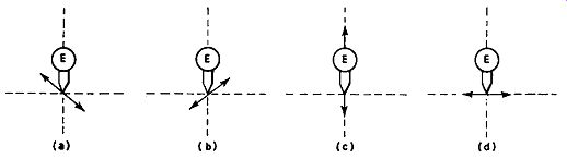
FIG. 10.7. The arrowed lines indicate how the recording stylus oscillates
under various conditions: (a) coil A (Fig. 10.6) energized; (b) coil
B energized; (c) both coils energized with in-phase signals; (d) both
coils energized with anti-phase signals.Now, if it is borne in mind that while the stylus is oscillating in
the various modes described a groove is being cut, it will be realized
that the impressed modulation will be a combination of lateral and hill-and-dale,
the same as that produced by the lateral-vertical system of stereo recording.
It will be understood, therefore, that the two systems are basically
identical. It comes down to a matter of phasing of the two signals; the
inclusion of a simple sum and difference network in the recording head
or pick-up circuit will permit the pick-up or recording head of one system
to operate with a recording made by the other. It should be noted, however,
that the 45/45 system has been accepted as an international standard.
The recommendations in this connection were withheld from publication for a time by the European record manufacturers, who were represented at the Zurich Conference in November, 1957, until it was perfectly clear that these harmonized with the views and recommendations of the Record Industry Association of America. There has been close co-operation between the recording companies regarding the standards for stereo disk records, and no doubt this has helped in the rapid graduation of the stereo disk from the laboratory, where it has been available for quite a long time, to the open market.
With regard to other record parameters, such as the diameter of the disk, speed and recording characteristics, the recommendations were that they should follow wherever possible the existing standards for microgroove records laid down by the International Electro-Technical Commission.
Thus it seems unlikely that a state of chaos will reign in relation to stereo disks as it did at one time with regard to the parameters of monaural disks.
With regard to right and left channels--as defined by the loudspeaker which supplies the sound to a listener in front of the loudspeakers--the standard is that modulation normal to the surface of the groove wall which faces the axis of the disk should supply the right-hand channel, while the modulation on the groove wall which faces away from the axis of the disk should supply the left-hand channel. This is really not very important from the user's point of view, since it is usually a simple matter to change the position of the loudspeakers or change over the pick-up connections to ensure that the right-hand modulation actuates the right-hand loud speaker.
Further, a maximum radius of 5 microns is recommended for the bottom of the groove, but the included angle remains the same as that of single channel microgroove disks. However, in order to reduce pinch effect and tracing distortion, the radius of the tip of the reproducing stylus requires to be reduced to the region of 0.0005 in.; the recommended limits are 12.5 microns minimum and 15 microns maximum.
COMPATIBILITY
There is another important standard relating to the phasing of the two channels: it is stated that lateral movement of the reproducing stylus shall provide equal, in-phase, acoustical signals from the loudspeakers. From this it follows that pick-ups designed for stereo reproduction are suitable also for the playing of normal single-channel microgroove records. This mode of phasing also results in a theoretically "compatible" record, which will thus provide a fully balanced single-channel signal when played with a single channel pick-up.
However, at the time of writing there is no monaural pick-up available with sufficiently small mechanical impedance to the vertical movement of the stylus to permit this concept of compatibility being exploited. Attempted playing of a stereo disk with even the best of pick-ups currently available will, without a doubt, wipe the stereo from the groove.
Apart from the high mechanical impedance of the vertical movement of the stylus, it must also be remembered that single-channel pick-ups are fitted with a larger stylus tip than is recommended for stereo disks.
This question of "phasing" the two stereo channels to secure a "compatible" record is worth further investigation. Let us look again at Fig. 10.6. Here we see that when the signals applied to coils A and Bare in phase, the stylus moves up-and-down as shown at Fig. 10.7 (c). This does not follow the recommended standard which, for the in-phase condition, requires the stylus to move parallel with the surface of the disk (i.e., laterally). This, however, is easily remedied by changing the phase of the signal in one of the channels so that it is shifted by 180 deg. Recording companies do, in fact, phase the two channels in this way for reasons of compatibility, as explained above.
Assuming in-phase signals from the stereo microphone system at the studio, which, for example, would be obtained by an announcer speaking in a position such as to provide sound waves of equal pressure and phase at the microphones, the signals at the stereo recording head are applied to the two electromagnetic systems in the manner which causes lateral modulation of the groove.
On playing the record, the phasing of the generating systems of the pick-up must also match, so that the corresponding lateral vibrations of the reproducing stylus cause in-phase signals at the two loudspeakers. This particular condition is, in effect, the same as that obtained by running two correctly phased loudspeakers on a single channel, which would be expected in view of the lateral modulation of the groove.
This illustrates the importance of maintaining correct phasing throughout the system, from the microphones to the loudspeakers. Only when this condition exists will the true stereophonic illusion be fully realized. The actual phasing of the two channels, from the aspect of the recording head serves essentially to modify the mechanical operation of the stylus to provide a compatible record-the phase of one channel is purposely reversed here, it will be remembered, to provide a lateral movement of the stylus for equal in-phase signals. This method of phasing also helps to reduce the tracing distortion and decreases the demands in relation to the vertical movement of the reproducing stylus.
STEREO PICK-UPS
While two stereo signals are required to cause complex vibrations of the recording stylus in accord with the waveforms of the signals, the vibrations of the reproducing stylus as it traces the complex groove produce signal voltages in the two generating systems of the pick-up of similar relative phase and level as those applied to the recording head during the recording process.
Clearly, if the construction of the pick-up is similar to that of the recording head then the movement of the armatures or coils in the pick-up will follow the same movement as the armatures or coils in the recording head, for a given mode of vibration of the stylus. Thus, the voltage produced in each generating system of the pick-up will, within limits, duplicate the voltage applied to each section of the recording head, through the medium of the complex stereo groove.
In practice there is some slight interaction, or cross-talk, between channels, caused by undesirable resonances in the pick-up and limitations of the recording head and the recording itself. The desirable minimum of cross-talk has been reckoned at 25 db: however, this may be rather an optimistic value, and it has been suggested that the total value of cross-talk may be as high as 10 db at high frequencies (the effect is more troublesome as the frequency is raised). While there are a number of unknown factors, tests indicate that a cross-talk value as high as 10 db has little adverse effect on the stereo illusion.
Stereo pick-ups range from crystal and moving-coil to balanced armature and variable-reluctance types. With its relatively high output voltage in relation to tracking weight, the crystal-cartridge has much to commend it, even though its top response may not quite reach the standard of low-level electromagnetic types.
The stereo crystal-cartridge element is formed of two slabs of crystal, each with its own electrodes, cemented together to form a "bimorph". The crystals are cut in such a manner that outputs are generated when one is subjected to a torque and the other to a flexure, and they are known as the "twister" and "bender" respectively. The vertical and lateral modulations of the groove are transmitted to the two crystals through a form of mechanical coupling so that an output is obtained from the bender crystal as the result of vertical movement, and an output is obtained from the twister crystal as the result of a lateral movement.
There is another arrangement whereby the crystals, instead of being cemented together, are mounted so that their faces form a 90-deg. vee shape.
Stylus movement is mechanically coupled to the crystals, but in this case it is possible to use two twister crystals, which require less stylus energy to provide an output-which is desirable in view of the improved high-frequency response.
As with crystal pick-ups, electromagnetic pick-ups for stereo must also have two sensing elements operated from a common stylus. There are always two coils, therefore, and these are invariably wound on a common magnetic circuit. The moving armature is arranged in such a manner that stylus movement in one direction induces an e.m.f. in one coil, while movement in the other direction induces an e.m.f. in the other coil. Two output voltages are thus obtained and, provided the phasing of the coils is correct, the relative phase of the signals will be as required for true stereo reproduction.
STYLUS
Owing to the very small tip radius of the stereo reproducing stylus, the rate of wear of the point is faster than for the 0.001-in. microgroove stylus.
For this reason, most stereo pick-ups are fitted with diamond styli as standard. This puts up the cost, but it is really essential when it is considered that a 0.0005-in. sapphire stylus tracking at 7 grams does not last much longer than about five hours! Most manufacturers aim at about 3-4 grams tracking weight, which increases the life of the sapphire stylus to about 70 hours; the diamond lasts some 20 to 30 times longer than this.
The reader should note that both pick-up channels require equalization to conform to the standards given in Section 7.
STEREO FROM TAPE
FIG. 10.8. The Truvox stereo head.
Stereo tape records have been available for a number of years both in Britain and America, having been introduced in this country by E.M.I., Ltd.
This company's "Stereosonic" tape records are becoming more popular as more people are buying tape recorders and converting them for stereo operation. Unlike the disk, however, which enjoys a considerably greater degree of popularity, stereo tape records are still mainly of interest to the specialist.
There is undoubtedly a great future for magnetic tape in stereophony, but from the point of view of the general public it seems likely that the disk will hold the field for some time to come. Of course, the disk has long been established, whereas tape is a relative newcomer. These is also the question of cost. The enthusiast already in possession of a single-channel record-playing system must buy a second amplifier and loud speaker and also a stereo pick-up in order to exploit stereo disks to the full. If he decides to start on tape, however, he will require a complete set of equipment, including a stereo tape deck (his original loudspeaker will do for one channel, of course). With tape records, the two stereo channels are recorded one above the other on standard ¼-in. tape. They are recorded in conformity with the C.C.I.R. recommended characteristic at a speed of 7½ in. per second. E.M.I. "Stereosonic" tapes, which are the only stereo tapes available in this country at the time of writing, are recorded with the recording heads in line across the tape. This makes it necessary to employ a stereophonic head for replay whose gaps are in line.
A stereophonic head of this kind is illustrated in Fig. 10.8. This is the well-known Truvox head, which can easily be fitted to the Truvox Mark III and Mark IV tape decks with very little trouble. By the inclusion of a Truvox Type K amplifier to provide a second channel, a Truvox R2 recorder or any Truvox tape deck can be used for the playing of "Stereosonic" tape records.
It is also possible to produce one's own stereophonic tape recordings, but a high level of studio technique is necessary for good results, "a good half track recording being preferable to a poor stereophonic recording", according to Truvox.
Other machines could be adapted to cater for the Truvox stereo head, and to help experimenters in this respect, details of the head are given. The gap is 0.00025 in. beryllium copper; output voltage 1-3 mV; impedance approximately 50,000 ohms at 10 khz; frequency response attainable with a suitable amplifier 50 to 15,000 hz; cross-talk better than 45 db; bias for recording 120 V r.m.s. approximately; recording current 0.1 mA approximately.
If it is required to play stereo tape records and one is already in possession of a tape deck and a single-channel hi-fi outfit, there is usually no need to go to the expense of adding a second complete reproducing/recording amplifier.
One scheme which can be adopted is to double-up on the hi-fi amplifier and loudspeaker (or if just starting in the field to obtain a stereo amplifier complete), replace the existing recording/replay head with a stereo model and feed the second channel from the head to the second hi-fi amplifier, or to the second channel of the stereo amplifier either direct or by way of a head amplifier.
A head amplifier will not be required if the amplifier has a low-level (1-3 mV) tape input channel, but a large number of amplifiers, although making provision for a tape input channel, require an input of some 200-300 mV of tape signal, and need a head amplifier to raise the low-level signal accordingly. The circuit of such an amplifier is given in Fig. 10.9. This is based upon the Mullard Type C tape amplifier, with equalization fixed for a tape speed of 7½ in. per second. The power requirements are quite modest, and can be obtained with ease from almost any hi-fi power amplifier.
There are various commercial head, or sub-, amplifiers on the market for those who do not wish to construct their own. A versatile unit is that by Cape Electrophonics of Southampton. In basic form this uses a single-valve circuit with a gain in the region of 100, but it can easily be modified for particular applications. For example, Model B is already set-up for use with a tape deck, and embodies equalization to C.C.I.R. recommendations.
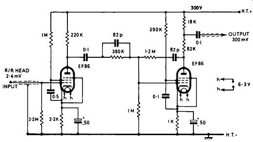
FIG. 10.9. Circuit diagram of a tape-head amplifier. This is based upon
the Mullard Type C tape amplifier, with equalization for a tape speed
75 in. per second.
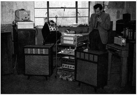
FIG. 10.10. Making a stereo tape recording of the BBC's stereo broadcast.
Now that stereo amplifiers are becoming popular, more manufacturers are adding tape input channels with sufficient sensitivity to operate direct from the replay head of a tape deck. This means that if one is interested simply in playing stereo tapes, the head circuits can be connected direct to the stereo amplifier, in the same way as can a pick-up. Once stereo amplifiers have become well established, stereo tapes could very much be popularized by a go-ahead manufacturer producing a reasonably-priced stereo tape player on the lines of a record player, and suitable for playing monaural as well as stereo tapes. Such an instrument would find a ready market among hi-fi enthusiasts who are not interested in making tape recordings. Instruments providing for both recording and reproduction are necessarily rather expensive, and this may be the reason why tape records have not made more rapid progress.
If a stereo head is added to a standard tape recorder or tape deck, single channel work can be carried on as usual, but if stereo recording is to be attempted, it would pay to obtain either a full-track erase head or a bulk erasure. It is very disconcerting to find that only one half of the tape has been erased after expending considerable effort in the creation of a stereo tape record.
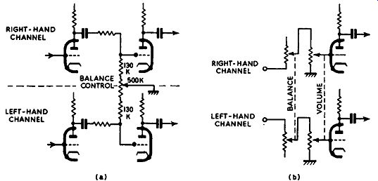
FIG. 10.11. Two balance-control systems: (a) circuit with variable loading;
(b) with balance control associated with ganged volume control.
STEREO FROM RADIO
This aspect of stereophonic reproduction is as yet in the experimental stage, at least in Great Britain. There have been a number of experiments in stereo radio broadcasts by the BBC, and these have proved remarkably interesting. Whilst television, medium frequencies and V.H.F.-F.M. channels have been utilized in these experiments, there is little doubt that the V.H.F. F.M. channels represent the ultimate solution to the problem of obtaining stereo from radio signals. With this in mind, several manufacturers of stereo amplifiers have incorporated two radio input channels. Further stereo experiments by the BBC will most likely use two V.H.F.-F.M. channels, as hitherto, so the enthusiast with two V.H.F.-F.M. tuners and a stereo amplifier will really be able to make the best of the experiments.
Two V.H.F.-F.M. tuners (E.A.R. switched units) were used by the author during the course of the experiments in May, 1958. Fig. 10.10 shows the set-up employed, with the author observing the operation of the tape deck. The two E.A.R. tuners are seen situated on the floor beneath the trolley-a handy device for tests of this nature. V.H.F.-F.M. signals were fed to these from a common aerial through a distribution system, and the stereo a.f. signals from the Third and Home programs were channeled to the amplifier in a Truvox tape recorder and to a Truvox Type K recording amplifier, seen on the second shelf of the trolley.
The recorder was fitted with a stereo head so as to record the stereo signals obtained from the two channels. In addition, two hi-fi amplifiers (a Pamphonic and a Pilot) received signals from the appropriate outlet sockets of the recording amplifiers so as to provide immediate reproduction from the two E.A.R. loudspeakers situated either side of the trolley. The set-up thus permitted the immediate reproduction of the stereo sound as well as the recording of the signals. The tests proved very successful from both aspects; excellent live stereo was obtained during the transmission and, on playing the tape recording afterwards, the performance was almost equal to the original. The tests were performed some 60 miles from the V.H.F.-F.M. transmitters, showing that stereo via radio is feasible in fringe areas and also that it can be recorded with remarkable ease.
When making stereo tape records, the accepted practice is to record the left-hand channel on the top track, that is when the tape is travelling from left to right with the active side away from the observer.
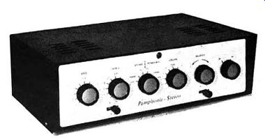
FIG. 10.12. The Pamphonic Type 3,000 stereophonic amplifier.
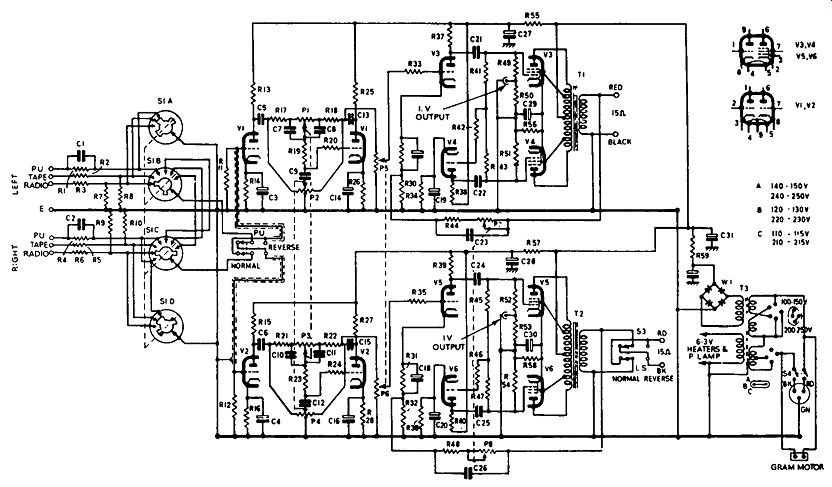
FIG. 10.13. Circuit diagram of the Pamphonic Type 3,000 stereophonic
amplifier. The component values are given on the opposite page.
---------- Note: All resistors ¼ W unless otherwise stated. ; Component values/or Pamphonic Type 3,000 stereophonic amplifier (see Fig. 10.13).
BALANCE CONTROL
If two separate control units or hi-fi amplifiers are used for the playing of stereophonic records or for reproducing stereo from the radio, it is essential to maintain optimum balance by very carefully adjusting the two volume controls. Tonal balance between the two channels is also important.
Stereo control units or amplifiers use ganged controls, so that operation of the common control knob will vary the volume or tone of the two channels in step. In addition to ganged controls, a balance control is often desirable so that the volume of one channel in relation to the other can be altered slightly to compensate for a difference between the sensitivities of the loud speakers, for example, or to counteract acoustical shortcomings of the listening room.
Two methods for obtaining balance control are given in Fig. 10.11.
Diagram (a) is a straightforward arrangement which varies the loading, and thus the applied signal, at the grids of the two triodes. An ordinary 500k linear volume control serves as the balance control, and the two 130-k resistors in series with it avoid excessive loading which would result in a fall of top response.
A more commendable arrangement is given in Fig. 10.11 (b). Here the balance control is directly associated with the ganged volume control. The balance control is also a ganged component, but is connected differentially, so that as it is rotated the signal input is increased in one channel and decreased in the other.
These controls can be installed in existing amplifiers if required, but care should be taken to position the circuit so that it does not affect the frequency response or incite overloading of the low-level stages.
STEREO EQUIPMENT
Because of the enormous difference between single-channel hi-fi and stereophony, there is little doubt that stereophony is destined to become the hi-fi of the future. It will be available from tape, disk and radio; the gradual development of the propagation of television and radio signals by way of cables instead of the ether will lend itself admirably to regular stereo broad casts on ordinary radio as well as television sound.
The change from single-channel sound to stereo is now taking place; stereo attachments are available for existing equipment and complete stereo amplifiers and control units. Stereo will not be adopted only by hi-fi enthusiasts, :is add-on units are already becoming available for the popular record player and radiogram. B.S.R. have adapted two of their "Monarch" record changers (Models UA8 and UAl2) to take stereo cartridges for stereo reproduction, and these are being supplied to leading manufacturers. Combined stereo-monaural pick-ups are also being developed. During the London Audio Fair in 1958, R.G.D. demonstrated that the " Victoria" radiogram is easily convertible for stereo operation by the fitting of a stereo pick-up cartridge and an additional loudspeaker-amplifier unit. The " Victoria" radiogram comes within the hi-fi category. of course; however. a number of ordinary record-players and radiograms of reasonable quality which are now on the market can readily be adapted to stereo operation.
Nevertheless, the hi-fi enthusiast will still wish to employ hi-fi amplifiers, pick-ups and loudspeaker systems, as hitherto. For really high-quality stereo reproduction, special attention will have to be paid to such things as turn tables and pick-up arms. Motor rumble will be found to be more trouble some with a stereo system than with a monaural system, since the stereo pick-up responds almost equally in all directions of movement of the stylus.
Consequently, a motor which is virtually rumble-free on a monaural system may exhibit a most disconcerting rumble when a stereo pick-up is incorporated.
There is also the question of the pick-up arm. If the pick-up is tracked at the ideally low pressure of 2-3 grams, this may be found to have too much friction in the main bearing. There may be a temptation to use a greater tracking pressure and a stylus point radius exceeding the recommended 0.0005 in. as a means of keeping the stylus in the groove. Such expedients should be avoided if possible, for a record once played under these conditions will never give its best when later it is played under the correct conditions.
The Pamphonic Type 3,000 stereo amplifier (Fig. 10.12) is of interest.
As may be seen from the circuit in Fig. 10.13, it employs two independent channels with ganged controls. There are three switched inputs catering for pick-up, tape and radio. These are selected by switch S1, which has six positions, giving three stereo positions and three monaural positions. The pick-up channel is compensated for R.I.A.A. (British Standard 1928:1955 Fine Groove) recording characteristic and is adjusted for use with a stereo crystal cartridge, while the radio and tape channels are substantially flat from 50 hz to 15 k hz and require signal inputs of l volt and 0·5 volt respectively for 5 watts output. Each channel is rated at 7.5 watts, and on the monaural positions the signal input is applied to both channels simultaneously, thus giving a total power output of 15 watts.
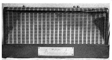
Fig. 10.14. The Sound Sales Tri-channel Mk. JV power amplifier. Baxandall
tone-control circuits are incorporated around stages V1 and V2 and provide
15 db variations at 50 hz and 10 k hz. There is also an interesting negative-feedback
balance control, P7 /PS, which serves to vary the gain of each channel
differentially by 6 db from the level position. A channel-reversing switch,
S2, is provided at the input of the amplifier, and is useful in cases
where the pick-up is connected wrong way round, or if the pick-up wires
are not known. There is also a phasing switch, S3, in the right hand
channel loudspeaker circuit. This avoids having to fiddle with the loudspeaker
connections.
The remainder of the amplifier follows conventional lines, details of which have already been given. It is, however, interesting to see an ECL82 connected in the ultra-linear mode. A metal bridge rectifier supplies h.t. for both of the channels, with excellent regulation.
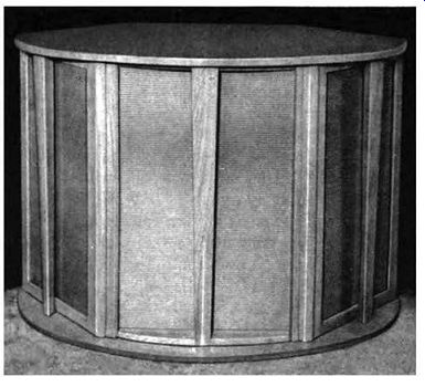
FIG. 10.15. The Sound Sales Tri-channel loudspeaker system.
Stereo tape equipment is marketed by E.M.I. for the playing of their Stereosonic tape records, and the G.E.C. also make a stereo tape-playing outfit. The latter incorporates the G.E.C. metal-cone loudspeaker system and presence unit, two BCS24 I 7 A/ 18A 12-watt amplifiers and the Truvox Type TR2 I I 2 tape deck.
Sound Sales, Ltd. market an excellent stereophonic version of their "Tri-Channel" equipment. Each channel uses, in effect, three separate amplifiers each covering limited sections of the frequency range and fed from an infinitely variable electronic cross-over system. Three loudspeaker systems are used on each channel, all being contained in a single cabinet of special design.
This arrangement avoids the necessity of reactive cross-over units at the loudspeakers themselves. The stereo Tri-Channel outfit comprises two Tri Channel main amplifiers, each rated at 50 watts, two Tri-Channel loud speaker systems and a Tri-Channel stereo control unit. The control unit has a stereo/monaural changeover switch, giving parallel ( 100 watts) or stereo connection. Sound Sales also market a transistorized stereo control unit, which has provision for direct replay from a low-level pick-up or tape head.
The Sound Sales Mk. IV power amplifier is illustrated in Fig. 10.14 and the loudspeaker system in Fig. 10.15.
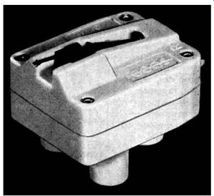
FIG. 10.16. The Acostereo crystal cartridge by Cosmochord, Ltd.
Especially worthy of mention is the stereo equipment by Cape Electro phonics, Ltd., comprising a stereo control unit of high standard, including a facility for the direct connection of a tape head, and associated power amplifiers. For enthusiasts not interested in building their own equipment, the control unit and amplifiers are available in ready-made and tested form, Cape Electrophonics also manufacture and market the "Cape Audio System", which includes facilities for recording and reproducing tape, as well as control units and very high-quality power amplifiers. The equipment is designed to very rigid specifications, thus ensuring results of professional standard.
At the time of writing stereo pick-ups in ever-increasing numbers are being made available which are suitable for playing the Nixa (Pye) stereo records. Fig. 10.16 illustrates the "Acostereo" crystal cartridge (Cosmocord, Ltd.), whose essential details are as follows. At a recorded level of 1.5 cm/sec an output of 200 mV is available; the frequency response is from 40-12,000 hz and the separation between channels at 1 k hz is better than 15 db. The cartridge will track at a minimum of 2 grams, but since this very small tracking pressure is dependent upon the lateral freedom of the tone arm, it is suggested that pressures in excess of 2 grams may be required, especially with auto-changers. The recommended load is 2 megohms, and the radius of the stylus tip is approximately 0.0005 in. to conform with the stereo standard for disk records.
In order to avoid undue wear on the stereo record and stylus, the lowest possible tracking weight should be used. A tracking weight in excess of 6-7 grams will ruin a 0.0005-in. stereo stylus after a few hours' playing, while the use of a 0.001-in. stylus, particularly if it is tracking fairly heavily, will ruin a stereo disk almost immediately.