by EVERT FRUITMAN
High-impedance voltmeter places more than 500,000 ohms between readable voltages as low as 2 millivolts and the meter!
HOW WOULD YOU LIKE TO BE ABLE TO MEASURE AGC AND OTHER low-level voltages without loading down the circuit, or your budget? Here is an instrument we call the Super-Sensitive Simple Voltmeter (SSSV) that will measure from 2-millivolts to 2-volts DC with an input impedance of 500,000 ohms, or higher. The circuit may be added to your present voltmeter, or built as a separate instrument. All of that is yours for the price of an op amp, a few resistors, and an inexpensive meter movement.
Theory
The primitive DC voltmeter shown in Fig. 1 is good for checking batteries and other similar low-impedance circuits. All of the current needed to move the meter's pointer comes from the circuit under test. In the low-voltage circuit of Fig. 2, the 1 milliampere that the meter needs for pointer movement represents more current than the circuit would deliver under normal operation. Since the meter's current loads down the circuit, the meter indications would be in error by a large magnitude, and the circuit would not operate normally while it is being tested. There are several simple remedies for those ills! By putting a simple high-impedance amplifier in front of the basic voltmeter, the circuit under test will not know that there is a voltmeter connected to it. The power needed to move the meter's pointer comes from the batteries and is controlled by the amplifier. The circuit continues to function in its normal manner and you are able to read voltages under working circuit conditions. There are many good voltmeters on the market that will not load down the circuit but they don't go down below 1 or 2 volts, which means that the reading is just barely seen as a flicker of the pointer coming off the zero mark.
The high-impedance amplifier permits the use of a low-sensitivity (1000 ohm/volt) VOM, or an inexpensive meter movement. Furthermore, voltages less than 10 millivolts may be read on a meter that normally needs 1 or 2 volts just to kick the pointer slightly.
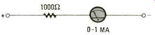
FIG. 1--THE TIME-HONORED voltmeter circuit that serves well in testing low-impedance
voltage sources accurately. Ideally suitable for checking batteries, power
supplies and low-impedance circuits. This is not the voltmeter to check low
AGC voltages.
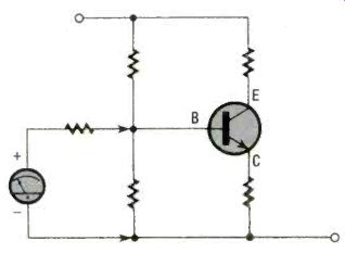
FIG. 2--DISASTER STRIKES when a low-impedance voltmeter attempts to measure
the base bias of this transistor circuit. The meter circuit radically alters
the resistive-biasing network causing abnormal operation and an incorrect
(and worthless) voltage reading. Even worse, the transistor may be destroyed.
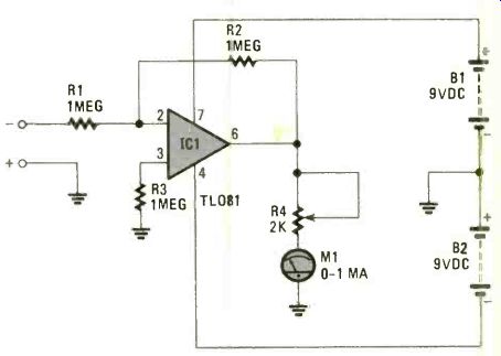
FIG. 3--BASIC CIRCUIT from which the SSSV grew. This one-range voltmeter
measures 0 to 2-volts DC accurately with usable increments of 0.05 volt.
The input impedance of this circuit is one-million ohms and draws only 2
microamperes maximum from the circuit under test.
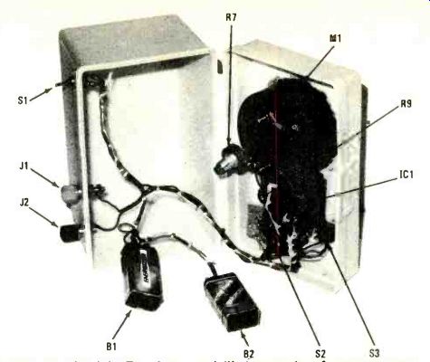
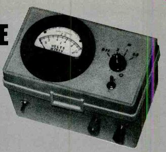
-- THE FLIP-TOP COVER of the card-file box makes for easy assembly of
the SSSV. With the heavy components on the cover, the unit is a bit top-heavy.
You may want to mount a burned-out transformer in the bottom of the light,
top-heavy plastic case to reduce the "tip-ability" and increase
the "heft-ability."
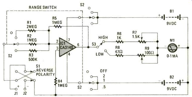
FIG. 4--BUILD THIS version of the SSSV. By setting switches S2 and S3 to
desired positions you can measure full-scale, DC voltages from 50-millivolts
to 2 volts. Input impedance is related to the selected resistor made by switch
setting of S2-thus selecting either R1, R2 or R3.
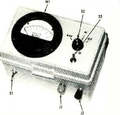
----- COMPLETED SSSV looks as it belongs on a lab bench. You may want
to change location of switches and that presents no problem in construction.
Location of J1 and J2 is ideal because test leads will not layover switches
and meter M1. Also, a slight tug on the test leads will not tip over the
meter case.
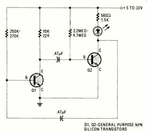
FIG. 5--LOW-POWER PILOT LIGHT is an optional feature it SSSV. Consider it
a project all by itself with application not only in SSSV, but in many other
projects where pilot-light indication its necessary and a transistor 9-volt
battery is used as the power supply. The low drain does not shorten the battery's
shelf life.
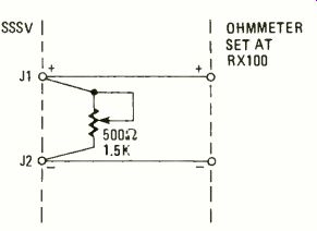
FIG. 6--SEEMS SCREWY to use an ohmmeter to calibrate a voltmeter, but that's
exactly the case. The ohmmeter is used as a constant current source to provide
a selectable scale deflection on the voltmeter’s HIGH range setting of S3.
Then, switch S3 is flipped to Low and adjustment is made. See text for details.
Getting advanced
The simplified voltmeter circuit in Fig. 3 shows an inexpensive 0-1 milliampere meter connected to an op amp, ICI, which raises the voltmeter's effective input impedance, and offers the opportunity for amplifying low voltages in high-impedance circuits. The input impedance in this case is one-million ohms. With R1 = R2 = 1 Megohm, 1-volt input gives 1-volt output at pin 6 of IC1. With R4 adjusted for just under 2000 ohms, then 2-volts input will give full-scale deflection on the meter; also, only 2 microamperes are drawn from the circuit under tests. That 2 microamperes could be cut down by making resistors R1 and R2, 10 Megohms each, but it really isn't necessary.
So far we have improved the loading characteristics of the basic meter. We can take advantage of the op amp's gain by making R2 larger that R1. Resistors, R1, R2 and R3 (Fig. 4) are lower in value, which reduces the input impedance somewhat. You may wish to make R5 larger and keep R1 as a fixed value.
To roll your own SSSV, you need to know that the gain of the system in Fig. 4 is the ratio of R5 /R1. That means that if R5 is 10 Megohms and R1 is 1 Megohm; then 0.1-volt input gives 1.0-volt output. That is a practical, but not theoretical, limit for what is being done here.
The overall sensitivity of the SSSV may be increased by adjusting the basic meter for 0.2 volts. That is done with the aid of S3 and resistors R8 and R9. See Fig. 4. Although the op amp is still delivering 1 volt to its output terminal, it has to deliver a little more current than before.
The additional current drain is well within its capabilities.
The net result of that last maneuver is a meter with six ranges covering 50-millivolt to 2-volt full scale, and an input impedance of at least 500,000 ohms. As little as 2 millivolts may be read on the lowest range of SSSV. That makes it a handy null indicator for Wheatstone bridges, and other DC nulling devices.
Putting it together
The cabinet for the SSSV is a 4 x 6-inch plastic, card-file box. Use a plastic case unless your meter states that it is calibrated for use on steel panels. If all you are going to make is the amplifier part and use it with an existing voltmeter, then the smaller 3 x 5-inch card-file box will be big enough.
Most of the smaller parts were mounted on a piece of surplus perfboard. That in turn was hung on the back of the meter movement, as shown in the photo. Of course, we're talking about wiring up the schematic diagram in Fig. 4. The meter, switches, binding posts, and if you like, the low-power pilot light, mount on the box. The layout may be anything that you like when you wire up your SSSV. The low-power pilot light, Fig. 5, draws very little power, and its friendly flicker is a good reminder to turn off the batteries. That is necessary because the meter normally sits on zero and requires no electrical zeroing. As a result, there is no real indication that the unit is turned on and slowly draining the batteries.
Use one of the Bi-FET op amps such as the CA3140 or the TL081 for best results in your SSSV. The input offsets in the 741 op amp won't allow its use on the extreme low ranges.
Checkout and calibration After everything is wired, and before the Bi-FET chip, IC1, is plugged in. connect the batteries to the SSSV and check with a voltmeter to be certain that pin 7 is positive with respect to pin 4. Refer to Fig. 4. If that is OK, turn S2 OFF and plug in IC1. Set the range switch, S3 for the highest voltage-2 volts in this case. Connect a voltmeter and a single cell from a flashlight across the input terminals. Turn it on. (use the polarity-reversing switch. S1, if needed) and adjust R7 (Fig. 4) for the same reading as the shop voltmeter.
So much for the high-range calibration. Accurate calibration of the low range is a bit more difficult unless you have access to a calibrated millivolt source.
The low-range calibration for the SSSV setup is shown in Fig. 6. It uses parts that you are likely to have around the shop. The wiper, (moving contact), and the ends of a 500-ohm potentiometer are connected to the input terminals of SSSV. An ordinary ohmmeter is paralleled across that potentiometer. Set the ohmmeter for R x 10 or R x 100. That makes it a crude current source. Set S2 on SSSV to 2 volts. Adjust the 500-ohm potentiometer for a meter reading of about 1/2 volt. Move range switch S2 down to the 0.5-volt position. Adjust the potentiometer for as close to 0.05 volts as you can. That will be the first major meter division. Move S3 (Fig. 4) to the low-range position and adjust R9 for full-scale deflection. Disconnect the ohmmeter and the extra potentiometer. That's it! You are ready to measure from a few millivolts, to 2 volts DC, with at least 500,000-ohms input resistance.
The Super Sensitive Simple Voltmeter will give you that extra measure of resolution that you always wanted on those low-voltage readings.
PARTS LIST FOR SSSV
RESISTORS
All fixed resistors are 1/4-watt, 5% values unless otherwise noted.
R1-2--Megohms (2 1-Megohm units in series)
R2, R4, R5--1-Megohm R3-500,000-ohms (2 1-Megohm units in parallel)
R6--1000-ohms R7-1500-ohms potentiometer
R8--47-ohms R9-100-ohms potentiometer
SWITCHES
S1--DPDT miniature toggle or slide switch
S2--3-pole, 4-position rotary switch
S3-SPDT miniature toggle or slide switch
ADDITIONAL PARTS AND MATERIALS
B1, B2-9-VDC transistor battery
IC1--CA3140E or TL081 BiFET operational amplifier
J1, J2-Multi-way binding post; one red, one black
M 1-0-1-mA panel meter, 2 to 3-in. circular or rectangular face
Plastic 4- x 6-in. card-file box (see text), battery clips, perfboard scraps, wire, hardware, solder, etc.
Adapted from: Radio-Electronics--Special Projects (Summer 1983, #7)
= = = =
Radio-Electronics--Special Projects (USA print magazine)
Also see: Single Sweeper One