We previously discussed the importance of low intermodulation distortion in the front end and the first mixer of a communications receiver. The diplexer was also considered, as a means of maintaining the low intermodulation distortion, all the way to the intermediate frequency amplifier. In addition, the noise performance of the i-f amplifier is crucial to the performance of the receiver. Without this, the receiver's noise figure could be dominated by the noise figure of the i-f system and the loss of the crystal filters used in it.
Figure 1 shows an i-f amplifier designed for the 9MHz i-f communications receiver. In this design, the traditional diplexer has been eliminated, as the input resistance of the Crystalonics CP-643 can be precisely matched with the 50 ohm output of the preceding mixer by adjusting the 250 ohm potentiometer. A total of 95 dB of gain is achieved with this approach, although an additional 15 dB can be obtained from the 1590's if needed, but with increased intermodulation distortion.
While the MC-1590 has a theoretical noise figure of about 6 dB, the i-f presented in Fig. 1 has a practical noise figure of 12 dB. This is compatible with the rest of the 9 MHz i-f receiver. It is interesting to note that some of the noise could be produced in the very high-gain stages following the crystal filter in spite of all the precautions taken in the layout.
In order to eliminate some of this noise, a second crystal filter which is matched with the first one in frequency, could be introduced at the output of the i-f as shown. This filter will almost completely eliminate the noise sidebands of the i-f amplifier.
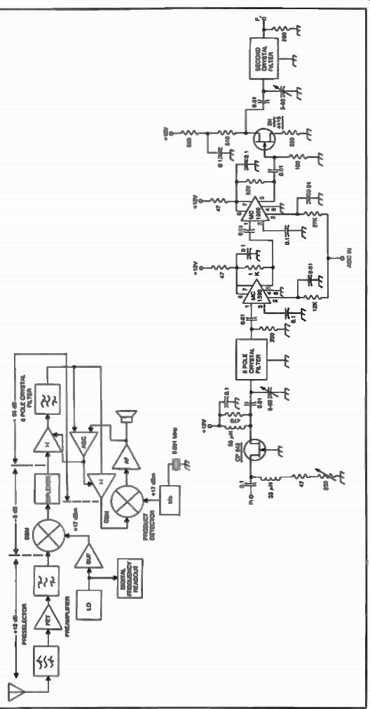
Fig. 1. A typical i-f amplifier as used in a 9 MHz i-f receiver.
Noise in an i-f can also be created by noisy local oscillators as we previously discussed, especially in synthesized systems which exhibit relatively poor phase noise performance. The effect can be noticed by gradually detuning a receiver with a steep-skirt crystal filter until the audible signal of a strong cw station falls outside the bandpass of the filter. If the receiver has a noisy local oscillator, an audible hiss would still be present at the output of the receiver, every time the cw signal was keyed in spite of the fact that the receiver is tuned to a different frequency. This "mushy" sound can great ly interfere with a small signal which we would like to copy.
Figure 2A, illustrates the impact of a noisy local oscillator on the i-f output of a communications receiver, while Fig. 2B, shows the same situation with a clean local oscillator. This example shows that the small signal is completely obscured in the i-f by the phase noise of the local oscillator.
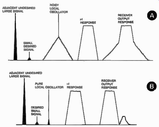
Fig. 2. Selectivity with noisy LO (A) and pure LO (B).
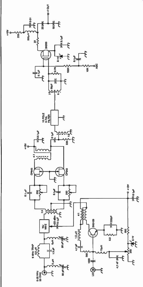
Fig. 3
It is believed that noise modulation occurs in the mixer and is caused by the mixer's balance. Using a balanced type mixer usually improves upon this problem. Although this is true to a certain extent, the real solution for eliminating noise modulation of an i-f is good filtering in the local oscillator but this can be quite a problem if a wide-range multi-loop synthesizer is used at the first local oscillator in a communications receiver.
Other popular integrated circuits such as the RCA CA3028 or the Plessey SL612 are often used in the i-f. They provide more than satisfactory results for many commercial and military receivers. FET amplifiers in balanced configurations are used for a lower noise figure and higher dynamic range. Figure 3 shows such an example. Two CP643 FETS are used in push-pull following a high-level mixer. Additional gain is provided by a dual HT amplifier using the 3N200 transistor.
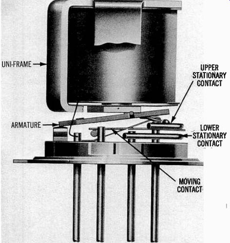
Fig. 4. Internal configuration of an rf relay which can be used to
switch filters in the l-f of a communications receiver (courtesy of Teledyne
Inc.).
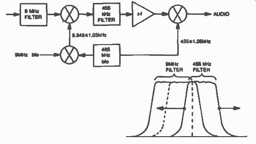
Fig. 5. Implementing variable bandwidth in a communications receiver.
Often, communication receivers require several bandwidths to be switched in and out in the i-f amplifier chain. The switching of different crystal or mechanical filters is typically accomplished with diodes in a way similar to that of preselector filters. Some receivers use FET switches for better isolation. Leakage and intermodulation distortion caused by the diodes becomes extremely important factors in the performance of a communications receiver, and some of the most modern radios today use relays to perform this function. Low capacity, high reliability rf relays are used to perform this switching.
Figure 4 shows the internal configuration of a Teledyne rf relay which was specifically designed for such an application. The relay is housed in a TO-5 package and can be mounted immediately adjacent to the filters.
Two relays are usually used for each of the filters involved.
Other relays can also be used to perform this function economically as shown in Fig. 5. In this example, two double-pole single-throw relays are used to select between two mechanical filters.
Variable bandwidths can also be implemented in a communications receiver as shown in Fig. 6. In this approach, the bandwidth of the 455 kHz filter is slid through the bandwidth of the 9 MHz filter (by varying the 455 kHz bfo) and only the information contained in the overlapped portion of the two filters is passed to the audio amplifier.
Fig. 5. Implementing variable bandwidth in a communications receiver.
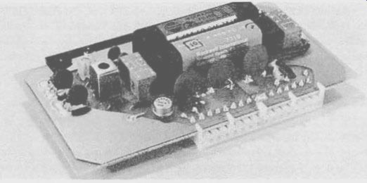
Fig. 6. Two double-pole double-throw relays are used to select mechanical
filters in this l-f amplifier.
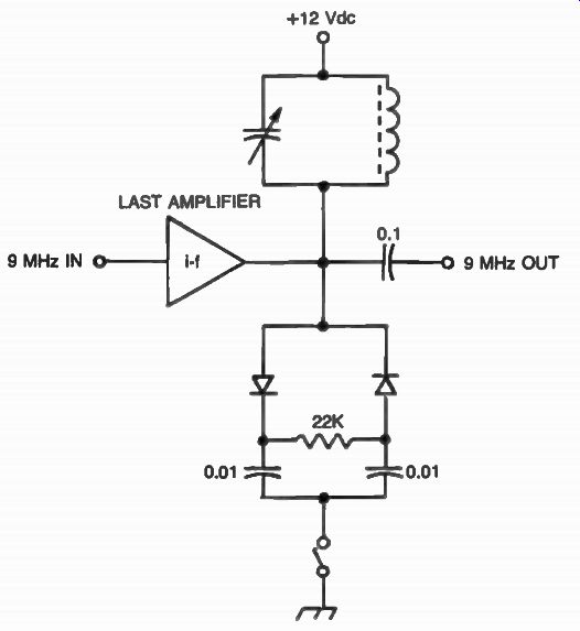
Fig. 7. A diode limiter noise blanker used in a 9 MHz i-f.
NOISE BUNKERS
The i-f amplifier is usually the place where noise blankers are implemented. The ideal function of a noise blanker is to discriminate against all forms of electrical noise which could interfere with the wanted information. The degree of discrimination is limited by the nature of the noise and because of it, noise blankers take many forms. Shown in Fig. 7 is the oldest form of diode limiter. This method of reducing pulsating noise is usually implemented in the audio portion of a receiver. Although an i-f type could be implemented as shown in Fig. 7. This low-cost method provides relatively poor results compared to the more sophisticated approaches.
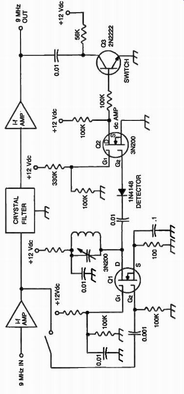
Fig. 8. A noise blanker circuit.
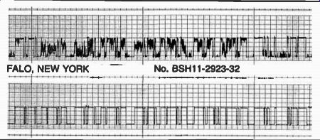
Fig. 9. Chart recorder information showing performance of two receivers
copying the same information through pulsating noise. Receiver at the
bottom is equipped with a noise blanker.
Shown in Fig. 8 is another method of producing a noise blanker circuit. The i-f amplifier chain is sampled for pulsating noise prior to the crystal filter, allowing for amplification and detection of fast rise-time pulses, which are amplified by the dc amplifier, which in turn will make transistor Q3 provide the ground path for the i-f signal during the pulse.
The net result of this effect is that the receiver will be blanked during the pulse, obscuring the noise, and providing much improved copy of the wanted signal. Figure 9 shows a chart recording of two receivers attempting to copy the same code information "CQ" through very heavy pulsating noise conditions, directly off the air. The audio output of the receivers were rectified through a simple half-wave detector and fed directly into the inputs of the chart recorder. The receiver at the top was not equipped with a noise blanker, while the receiver at the bottom had a noise blanker circuit of the type described here. This demonstration shows that the noise blanker is a worthwhile design addition to a communications receiver.
There are several other noise blanker designs today. The Collins approach uses a separate receiver which is tuned to a frequency where there are no intelligent signals expected. The pulsating noise is processed through a superheterodyne approach and the detected signals are used to shut off the main receiver much the same as previously described.
While the methods presented in this Section are effective in most noise situations, sometimes they do not perform as well depending on the nature of the pulsed signals received. New and complex noise blankers are sometimes used in communications receivers. They process the information received and adapt to the nature and length of the signals providing selective cancellation of certain types of pulses.
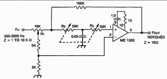
Fig. 10. Circuit diagram of a variable frequency audio notch filter.
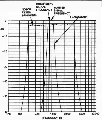
Fig. 11. Frequency response of the notch filter shown at A. Cancellation
of an unwanted signal located within the passband of a communications
receiver is evident in this example.
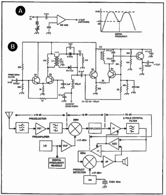
Fig. 12. Implementing an i-f notch filter.
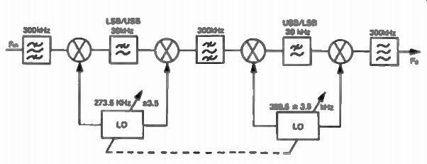
Fig. 13. Block diagram of the band-pass tuning process.
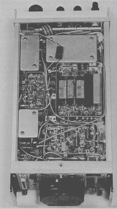
Fig. 14. Bottom view of the Cubic HF-1030 communications receiver
showing the rf input module, the AM/agc module and the 455 kHz i-f filter
module (covers removed) (courtesy of Cubic Communications).
THE NOTCH FILTER AND THE BANDPASS TUNING MECHANISM
The notch filter is an interesting and very useful function in a communications receiver. Its purpose is to allow the operator to cancel out one or more unwanted signals which fall within the receiver's passband. This is usually accomplished at audio frequencies with the help of a tunable audio rejection filter of very high Q. Figure 10 shows the schematic diagram for a variable Q, wide range notch filter which can be used in a communications receiver and can provide 40 dB of attenuation within its passband (300 Hz to 3 kHz). The design is a twin "T" network filter using feedback. The frequency control is performed by R2 and R3 which are two potentiometers coupled together on the same shaft.
Shown in Fig. 11 is the frequency response of the notch filter showing an unwanted cw interfering signal located by 100 Hz away from the received carrier in the i-f of a communications receiver. This example shows that the notch filter is a powerful tool in combating unwanted interference. A more efficient way of implementing notch filters is to design them directly at i-f frequencies prior to AGC-ing.
Figure 12A, shows a means of pulling a 9 MHz crystal in an i-f providing a variable notch over the bandpass of the i-f. About 40 dB of cancellation can be obtained with this method. A more sophisticated approach is shown in Fig. 12B, where a dc voltage is used with a wide range varactor in a series-resonant crystal configuration.
Another method of eliminating unwanted interference in a communications receiver is bandpass tuning shown in Fig. 13. This technique was introduced by Collins Radio Co. and was used extensively by several manufacturers. It provides continuous shifting of the audio passband response through the i-f bandwidth, allowing rejection of some unwanted signals. The system contains four mixers, three band-pass filters, two low-pass filters and two local oscillators which track together. Also, see Fig. 14.
This example shows that implementing bandpass tuning in a Communications Receiver is a complex matter. High-level mixers should be used to minimize intermodulation distortion which could be created quite easily in a multi-conversion system.