Too many times, designers of otherwise well engineered communications receivers fall into the trap of using inexpensive, readily available audio amplifiers, especially in integrated circuit forms, without considering the harmonic distortion performance of these devices which sometimes exceeds 20%. The use of a good audio amplifier is imperative in the design of a high quality communications receiver. A well designed amplifier capable of continuous power output of 2 to 3 watts, (Institute of High Fidelity--IHF) and exhibiting a total harmonic distortion of no more than 1.5% is highly recommended here. Tailoring of the frequency response to match that of the i-f is also highly recommended. Usually this is achieved by installing a high-pass and a low-pass filter network prior to the amplifier as shown in Fig. 1.
Figure 2 shows the schematic diagram for a 3 watt audio amplifier which exhibits a typical harmonic distortion performance of less than 1%. This design uses two complementary-symmetry, emitter-follower power transistors. Negative feedback is used in this circuit to reduce distortion and improve stability. Two-tone intermodulation distortion was measured to be better than 70 dB down at 4 watts output using 400 Hz and 2 kHz tones mixed 4:1. Further tailoring of the feedback circuitry might be necessary to achieve this performance.
The intermodulation distortion performance of the audio amplifier is just as important as the intermodulation distortion of the rest of the receiver if performance is to be maintained throughout. This statement is also true for the transducer, the speaker, or headphones used. When building this amplifier, the final transistors should be heat sunk and electrically insulated from ground.
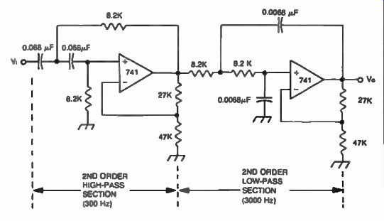
Fig. 1. Tailoring frequency response of an audio amplifier in a communications
receiver.
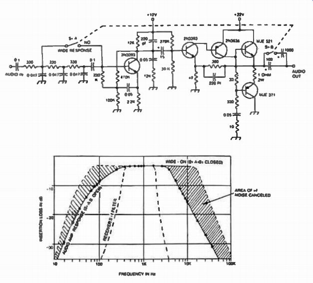
Fig. 2. Practical low distortion audio amplifier for a communications
receiver showing frequency response. This design is tailored so that
frequencies above 3 kHz are greatly attenuated, (Si-A, B, open) providing
effective cancellation of noise generated in the stages following the
i-f filter. A wider response can be achieved by closing switch Si-A,B
as shown.
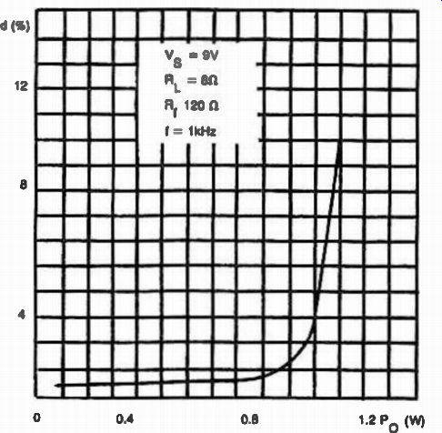
Fig. 3. Distortion performance of the TBA 820 audio amplifier versus
power output.
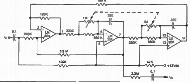
Fig. 4. Variable-frequency audio active filter. Range is 500 Hz to
2 kHz.
Shown in Fig. 1 is an integrated circuit audio amplifier using the TBA 820 which is rated at 2 watts. This design exhibits acceptable performance below 1 watt. Above this level, harmonic distortion increases rapidly accounting for poor performance especially when trying to copy weak signals. Figure 3 shows the distortion versus output power performance of the TBA 820. Additional selectivity can be obtained in the audio portion of a communications receiver. This is accomplished through the use of active filters such as the one shown in Fig. 4. This is a state-variable filter using three operational amplifiers in a unity-gain configuration. This design provides sharp tuning for cw signals over the frequency range of 500 Hz to 2 kHz.