Designing and building a high performance communications receiver is probably one of the hardest tasks, an individual or a company can undertake.
Although it is relatively easy to put together building blocks and combine them to achieve electrical performance, the implementation of these blocks in the total ensemble of the package can make the difference between failure and success.
The actual design of a communications receiver involves many sciences from mechanical to digital. Figure 22-1 shows the actual implementation of a high performance communications receiver which I designed and built. Electrically the system is a double conversion approach with a first i-f at 75 MHz and the second i-f at 455 kHz. A very high level mixer is used in the front end allowing for an intercept point of +22 dBm. A classic Vfo is used in conjunction with crystal oscillators providing a resolution of 2 kHz per revolution of the main knob. This, combined with narrow switchable filters makes for an extremely sharp communications receiver. To provide maximum isolation, the Collins mechanical filters used in the second i-f are switched with relays. Frequency is read through a digital display with a resolution of 100 hz. The layout of the receiver shows a compartmented approach.
All circuits are built on 3 1/2 x 5 inch PC boards and gold-plated connectors are used throughout. The advantage of this design is mainly that circuit modifications and improvements are possible without altering the actual receiver.
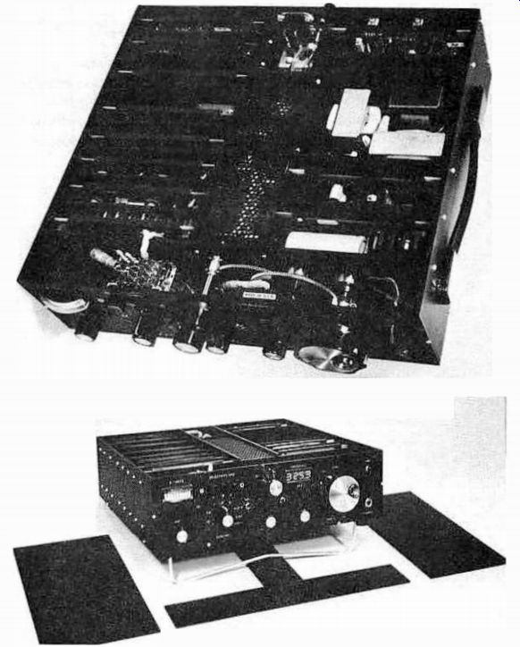
Fig. 1. A high performance communications receiver designed and built
by the author.
Over the years, many modifications have been implemented in a continuous search for technical excellence. Mechanically, the receiver is made of anodized black aluminum. All parts have been extensively machined and there are 186 screws in the system. The gear drive exhibits no backlash because of its different design. Light magnesium gears are used throughout. The variable frequency oscillator is driven by this gear train and is located in a closed compartment in the middle row close to the variable tuning oscillator (board) which can also be un-plugged. The receiver has three tops, a T-like top which covers the mechanics, and two hinged side covers which cover the electronics. Upon closing the covers, each circuit board is fully isolated in its own housing because of the walls between the compartments. The electrical interconnections between the boards are provided through two motherboards located on the bottom of the receiver. All interconnect circuits are either shielded or etched into the motherboards. The bottom cover is only one-quarter of an inch from the circuits, providing extra shielding. There are two extender boards pro- vided, should any troubleshooting be necessary. When not in use, they are packed in a plastic bag and housed in the transformer compartment. The receiver weighs 15 lbs and is fully portable.
Designing and building a high performance communications receiver is a good test of technical maturity for any individual who dares to attempt it. It is my opinion that such a multi-science test should be of significant value in asserting the engineering level of new college graduates, who will be faced with signal processing problems much similar to those encountered in a communications receiver in their future careers.