The phenomenon of interaction between sound and light was suggested by Louis-Marcel Brillouin* some sixty years ago. This theory was based on the hypothesis that monochromatic (single frequency such as red, green, etc.) Light would be diffracted in the presence of sound. This principle was proven in 1932 when the diffraction effect was observed in an experiment involving a source of filtered light that illuminated a column of water into which sound has been generated. Proper adjustment of the angle of incidence of the light source, allowed for the first-order diffraction line to become more intense while providing cancellation of the other lines. This angle was later called the Bragg angle and the phenomenon constitutes the basis for the acousto-optical (A/0) receiver, or as it is sometimes called, the Bragg-cell receiver.
In a Bragg-cell receiver, such as the one shown in Fig. 1, several rf signals of interest which are present at the antenna are converted to a wide-band i-f (40 MHz) centered, in our case, at 70 MHz. This is a typical superheterodyne process, and the signals contained within the i-f are further amplified by a high-gain high-dynamic range i-f amplifier, and are finally applied to the Bragg-cell through a piezoelectric transducer which is bonded to it. See Fig. 2.
The Bragg-cell is a block of very pure crystalline material, usually quartz or lithium niobate, approximately 1 cm x 1 cm x 10 cm in size. When excited by electrical signals within the pass-band of its transducer, the Bragg-cell is internally exposed to sound waves corresponding to the signals received.
*Louis-Marcel Brillouin (1854-194B). A French physicist, famous for his ferromagnetic theory, perpetual motion opposition. and Brillouin scattering phenomenon.
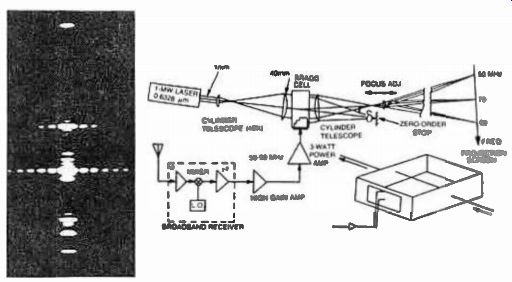
Fig. 1. The Bragg-Cell receiver principle, and typical display of
received signals.
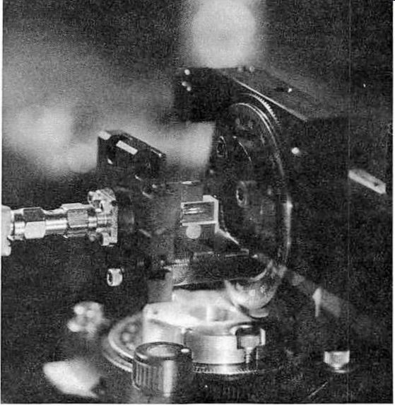
Fig. 2. Bragg-Cell signal processing is being developed by GTE-Sylvania
for a variety of applications. The beam from a Helium-Neon laser is diffracted
by the acoustic wave in the Lithium Niobate Bragg-Cell (courtesy of GTE-Sylvania).
If a beam of monochromatic light such as that produced by a laser is injected at the certain angle into the Bragg-cell, an instantaneous deflection will occur for each of the sonic signals traveling through it. This happens because the acoustic energy in the material causes changes in the refractive index between the peaks and valleys of the wave. The resultant diffraction pattern is an instantaneous display of the signals which can be viewed panoramically on a screen within the range of the signals applied to the transducer. The deflection angle and the intensity of the light beam are proportional respectively to the frequency and power of the signals being received.
The Bragg-cell receiver can be viewed as a parallel-processing device which acts as an optical Fourier transformer that continuously converts the time varying input into discrete frequency sets represented by separate instantaneous beam diffraction angles corresponding to each frequency.
The instantaneous nature of the Bragg-cell receiver allows for a high probability of intercept (POI) since many signals can be "viewed" at the same time, as in the case of a radio telescope. Detection of the displayed signals is implemented by focusing the multiple light beam on a linear array of PIN photodiodes which are spaced very closely together. The position of each detector corresponds to a specific frequency within the band-pass of the receiver allowing for parallel frequency detection of all signals within that band. As many as a thousand detectors could be incorporated into such a signal collection installation, allowing for a typical frequency cell resolution of 1 MHz or less.
While not completely understood, from an application point of view, this type of receiver is envisioned as an instantaneous spectrum analyzer, identifying signals of interest and directing conventional digitally programmable receivers to the particular frequency for narrow-band analysis.
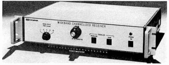
Fig.
3. A Bragg-Cell receiver developed by GTE-Sylvania (courtesy of GTE-
Sylvania).
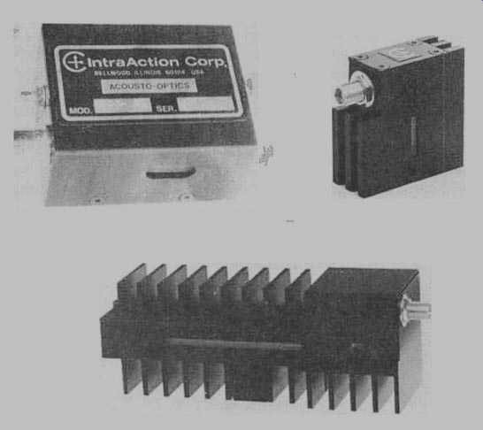
Fig. 4. Several commercially available Bragg-Cells (acousto-optic
deflectors), which can provide a high number of resolvable positions
(as many as 1000 spots) (courtesy of Intra-Action Corp.).

Table 1. Typical Performance Characteristics for a Bragg-Cell Receiver.
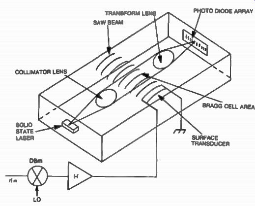
Fig. 5. Integrated acousto-optic receiver. A solid-state laser, optical
elements, the Bragg-Cell, and the array of photo detectors are all incorporated
on the same substrate, significantly reducing the size of the receiver.
There are few Bragg-cell receivers in existence today. Figure 3 shows a Bragg-cell channelized receiver developed by GTE-Sylvania, and shown in Fig. 4 are some commercially available Bragg-cells manufactured by IntraAction Corp. The typical performance of a Bragg-cell receiver is shown in Table 1. This table shows that one of the disadvantages of the Bragg-cell receiver is its limited dynamic range.
Other disadvantages of this type of receiver are its mechanical complexity associated with the packaging of the laser source, optical train and the detector array. New approaches in Bragg-cell receiver technology are looking at replacing the relatively bulky neon-helium laser with solid state devices which can be incorporated together with the Bragg-cell, lenses, and photosensors on the same substrate as shown in Fig. 5.
In conclusion, acousto-optical signal-processing technology has been emerging from the experimental laboratory development phase into an advanced process of signal collection with wide band applications. While still in its infancy, the Bragg-cell receiver should provide an improved signal processing tool in a dense rf spectrum.